-
Paper Information
- Next Paper
- Previous Paper
- Paper Submission
-
Journal Information
- About This Journal
- Editorial Board
- Current Issue
- Archive
- Author Guidelines
- Contact Us
American Journal of Biomedical Engineering
p-ISSN: 2163-1050 e-ISSN: 2163-1077
2012; 2(6): 278-286
doi: 10.5923/j.ajbe.20120206.07
The Mechanical Properties of a Porous Ceramic Derived from a 30 nm Sized Particle Based Powder of Hydroxyapatite for Potential Hard Tissue Engineering Applications
 Abstract
 Reference
 Full-Text PDF
 Full-Text HTML
Gérrard Eddy Jai Poinern, Ravi Krishna Brundavanam, Xuan Thi Le, Derek Fawcett
Murdoch Applied Nanotechnology Research Group. Department of Physics, Energy Studies and Nanotechnology School of Engineering and Energy, Murdoch University, Murdoch, Western Australia 6150, Australia
Correspondence to: Gérrard Eddy Jai Poinern, Murdoch Applied Nanotechnology Research Group. Department of Physics, Energy Studies and Nanotechnology School of Engineering and Energy, Murdoch University, Murdoch, Western Australia 6150, Australia.
| Email: |  |
Copyright © 2012 Scientific & Academic Publishing. All Rights Reserved.
In this paper, synthesised nanometre sized hydroxyapatite (nano-HAP) powders composed of spherical 30 ± 5 nm particles were compacted and sintered at temperatures ranging from 650 to 1250℃ to form ceramics of varying porosity and mechanical strength. The size, crystalline structure and morphology of both the synthesised nano-HAP particle powders and the compacted and sintered ceramics were investigated using both X-ray diffraction (XRD) and Field Emission Scanning Electron Microscopy (FESEM). Further characterisation techniques such as Brunauer-Emmett-Teller (BET) particle surface area, porosity, bulk density, Vickers hardness and yield strength at various sintering temperatures were tested on sintered pellets and evaluated.
Keywords: Hydroxyapatite, Nano-Ceramics, Crystalline Structure, Porosity, Vickers Hardness, Yield Strength
Cite this paper: Gérrard Eddy Jai Poinern, Ravi Krishna Brundavanam, Xuan Thi Le, Derek Fawcett, "The Mechanical Properties of a Porous Ceramic Derived from a 30 nm Sized Particle Based Powder of Hydroxyapatite for Potential Hard Tissue Engineering Applications", American Journal of Biomedical Engineering, Vol. 2 No. 6, 2012, pp. 278-286. doi: 10.5923/j.ajbe.20120206.07.
Article Outline
1. Introduction
- Hydroxyapatite (HAP)[Ca10(OH)2 (PO4)6] is a hexagonal structured ceramic composed of calcium phosphate groups that is very similar to the mineral component found in bone tissue. It is this close chemical similarity between synthetic HAP and the natural inorganic bone matrix component that has resulted in the extensive research effort to employ synthetic HAP as a bone substitute and/or replacement in several clinical procedures[1, 2]. Synthetic HAP is one of the most attractive ceramics for many biomedical engineering applications due to its four main inherent properties: 1) it’s biocompatibility to surrounding body tissues; 2) its biodegradability in situ is slow; 3) it provides good osteoconductivity; and 4) it has good osteoinductivity capabilities[3-5]. A recent investigation by Taniguchi et al. revealed that sintered HAP in contact with cellular material provided a good biocompatible response to soft tissues such as skin, muscle and gums[6]. It is this favourable tissue response that has made synthetic HAP an ideal candidate for a wide range of hard tissue engineering applications such as; bone repair, bone augmentation, coating metal-composite implants and as a filling material in both bone and teeth surgical procedures [7-9]. For many of these biomedical engineering applications, a dense HAP ceramic material, which exhibits the required mechanical properties for load bearing, is needed to meet the requirements of an effective hard tissue scaffold. The scaffolds architecture has a significant role to play in determining how effective the surrounding bone tissue integrates with the implanted scaffold[10]. The rate and degree of bone in-growth into the scaffold structure or matrix is influenced by the pore size and the interconnecting properties of the pores within the scaffold matrix[11, 12]. The porosity, or storage capacity, of porous HAP can be defined as the percentage of space in a material not occupied by the ceramic matrix, usually called the volumetric porosity. In the case of cortical bone the pore size ranges from 1 to 100 µm with typical volumetric porosities ranging from 5 to 10%[13]. HAP ceramics with low volumetric porosities generally have high mechanical properties but provide only limited opportunities for cell and tissue in-growth. Porous HAP ceramics have the potential to provide a good biological environment to promote cell adhesion, cellular interactions, proliferation, and migration. The downside to an increase in porosity is the decrease in its mechanical properties, such as strength, stiffness and elastic modulus. Both the cellular response and the mechanical properties are dependent upon the pore size, porosity, interconnecting porosity and pore distribution[2]. The American Society for Testing Materials (ASTM) has defined porous materials into three classifications, interconnecting (open pores), non-connecting (closed pores), or a combination of both[14]. The interconnecting porosity within the matrix scaffold is a very important property since it permits fluid flow through the porous ceramic material, which is crucial for cellular growth. The effectiveness of the fluid flow through this natural plumbing system is called the permeability.Pore sizes smaller than 10 µm define a micro-porous structure in the ceramic. The size of these micro-pores usually prevents the influx of cells into the pore structure, but fluids are still able to penetrate into and flow through the scaffold structure. When the pore size is greater than 10 µm they are classified as macro-pores and are large enough for both cells and fluids to enter the pore structure. The macro-pores have a large pore surface area to bulk volume ratio which actively promotes cell adhesion, cellular interactions, proliferation, and migration. Using techniques that can assist in forming a porous structure within the ceramic has many advantages, since the architecture of the porous structure can be controlled. The ability to select the pore size, pore geometry and the interconnecting porosity allows cell and tissue growth throughout the porous scaffold structure. For example bone forming cells, osteoblasts grow far more efficiently when they are attached to a substrate rather than being suspended in a culture medium. In fact the ability of natural bone to bond with HAP is a major reason why many researchers have studied and continue to investigate this ceramic for biomedical applications[15]. When the pores are large and open, the HAP matrix is usually formed into a strut like structure, which forms the pore walls. The resulting interconnecting open face pore structure produces a network of struts that form flow channels throughout the matrix. The pore channels are conducive for cell and tissue colonisation. In addition, the pore channels provide high permeability flows for the cells to be supplied with nutrients and for the removal of metabolic waste products from normal cellular activity[16]. This type of pore structure is ideal for cells and tissue growth, but it has poor mechanical properties. On the other hand, if the pores are closed, the HAP matrix forms a network of interconnecting plate like structures that produces a high density solid. This configuration prevents the passage of fluids or cells to neighbouring pores or the rest of the scaffold. Since the architecture of the scaffold requires a significant amount of porosity to accommodate fluid transfer and tissue in growth, an effective balance between porosity and the mechanical properties such as strength must be achieved. It simply comes down to the fact that when the porosity increases, the strength, along with other mechanical properties of the scaffold decrease rapidly. Because strength is an important property of a load-bearing scaffold, the internal architecture of the scaffold structure must be carefully considered since it strongly influences the ability of the scaffold to resist load[17]. Therefore, by adjusting the porosity, it is possible to fine-tune the strength of the scaffold for a site-specific biomedical application[18]. Furthermore, as the porosity increases, there is an increase in matrix surface area which is exposed to the environmental effects of erosion, changing surface chemistry and cellular activity. For example, bioactive materials like HAP, exhibit surface modification with time when exposed to bodily fluids and cellular activity. So the application of high porosity, low strength biomaterials is restricted to non-load bearing applications. In this particular application, where the initial function of the scaffold is not load-bearing, then the porous scaffold can provide an effective functional implant or biomedical device. Therefore, being able to fabricate and fine tune a particular strength/porosity HAP scaffold provides greater flexibility in addressing the needs of the site specific application. To achieve this goal there is a need to use powder compaction-sintering techniques to fabricate a dense HAP ceramic with the appropriate degree of porosity to meet the requirements of a successful tissue scaffold platform. The process usually begins with the synthesis of the HAP powder via a wet chemical method and subsequent heat drying. The drying stage usually forms large agglomerates, which often form structurally weak HAP ceramics with inhomogeneous pores after compaction and sintering. To prevent particle agglomeration, the use of ultrasonic irradiation during wet milling is an efficient means of dispersing and de-agglomerating the sample particles during the grinding process[19]. After the milling process, the resultant powders are composed of fine, uniformly sized particles in the nanometre range, and both homogeneous in phase and chemical composition with very little particle agglomeration[20, 21]. The strength of the resultant powder, compaction and sintered HAP ceramic mainly depends on grain size, grain distribution, porosity, and other micro-structural defects. Hardness testing is frequently used to characterise mechanical properties, such as strength, of bulk solid samples and thin films. The hardness technique involves pressing a hard indenter of well-defined geometry into the surface of the sample under a predetermined load[22]. Indentation is considered an attractive method for assessing the mechanical properties of materials since it is basically a non-destructive in contrast to other techniques such as bending, compression and extension of samples. The Vickers diamond pyramid indenter, whose opposite faces have the included angle of 136º is one of the mostly widely accepted indenter technique for determining the hardness of ceramic materials and is used in this research work[23].The aim of this study was to compare the porosity and strength of HAP ceramic scaffolds produced via a using powder compaction-sintering technique. The synthesised nano-HAP powders were compacted and sintered at temperatures ranging from 650 to 1250ºC to form ceramics of varying porosity and mechanical strength. The size, crystalline structure and morphology of the nano-HAP particle powders synthesised were investigated using both X-ray diffraction (XRD) and Field Emission Scanning Electron Microscopy (FESEM). In addition, the size, crystalline structure and morphology of the compacted and sintered ceramics were also studied using XRD and FESEM. Further characterisation techniques such as particle surface area, porosity, relative density, hardness and yield strength at various sintering temperatures was investigated.
2. Materials and Methods
2.1. Materials
- The main reactants used to synthesis the n-HAP powders were calcium nitrate tetrahydrate[Ca(NO3)2.4H2O] and potassium di-hydrogen phosphate[KH2PO4], while the pH control of the solutions was achieved by the addition of ammonium hydroxide[NH4OH]. All analytical grade reagents used in this work were supplied by Chem-Supply (Australia), while Sigma-Aldrich (Castle Hill, NSW, Australia) supplied the Stearic acid,[C18H36O2] which was used as a binding agent during the powder compaction procedure. The solutions containing the reactants were synthesised under the influence of ultrasound irradiation, which was provided by an UP50H Ultrasound Processor[50 W, 30 kHz, MS7 Sonotrode (7mm diameter, 80 mm length)] supplied by Hielscher Ultrasound Technology. All aqueous solutions used throughout this study were made using Milli-Q® water (18.3 MΩ cm-1) produced by an ultrapure water system (Barnstead Ultrapure Water System D11931; Thermo Scientific, Dubuque, IA).
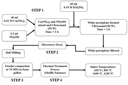 | Figure 1. Schematic of the synthesis procedure used to produce nano-HAP powders and the sintering temperatures used in the processing of the test pellets |
2.2. Synthesis of n-HAP Powders
- The procedure for producing the n-HAP powder begins with adding a 40 mL solution of 0.32M calcium nitrate tetrahydrate into a small glass beaker. The pH of the solution is then adjusted to 9.0 by slowly adding and mixing approximately 2.5 mL of ammonium hydroxide. The resulting solution was then exposed to ultrasonic irradiation for 1 h, with the processor set to 50 W and maximum amplitude. At the end of the first hour a 60 mL solution of 0.19 M potassium di-hydrogen phosphate was then slowly added drop-wise into the first solution while undergoing a second hour of ultrasonic irradiation. During the second hour, the Calcium/Phosphate[Ca/P] ratio was maintained at 1.67, while the pH of the solution was checked and maintained at 9.0. At the end of the second hour, the solution was then filtered using centrifugation (15,000 g) for 20 minutes at room temperature, the resultant white precipitate sample was then placed into a fused silica crucible, which was supplied by Rojan Advanced Ceramics Pty Ltd, Western Australia. The crucible was then placed into a standard domestic household microwave (1100W at 2450 MHz-LG® Australia) for a thermal treatment period of 40 minutes at a power setting of 100 %. At the end of the thermal treatment the sample ended up as a white agglomerated mass. Once cooled, the sample was ball milled to break up the agglomerations and produce an ultrafine n-HAP powder, see schematic procedure presented in Figure 1. This synthesis procedure is repeated until a sufficient amount of the n-HAP powder was available for advanced characterisation and for the manufacture of pellets needed for further testing to determine properties such as porosity, density, hardness and elastic modulus.
2.3. XRD and FESEM Characterisation Techniques
- The size, crystalline structure and morphology of both the synthesised nano-HAP particle powders and the compacted - sintered ceramics were investigated using both X-ray diffraction (XRD) and Field Emission Scanning Electron Microscopy (FESEM) techniques. Powder XRD spectra were recorded at room temperature, using a Siemens D500 series diffractometer[Cu Kα = 1.5406 Å radiation source] operating at 40 kV and 30 mA. The diffraction patterns were collected over a 2θ range from 20° to 60° with an incremental step size of 0.04° using flat plane geometry. The acquisition time was set at 2 seconds fro each scan. The powder XRD spectrum was used to identify the purity of the final nano-HAP powders and any other phases that were present, see Figure 2. The crystalline size of the particles in the powders was calculated using the Debye-Scherrer equation[Equation 5] from the respective XRD patterns and estimated from the corresponding FESEM micrographs, see Figures 3. In addition, the fraction of crystalline phase (Xc) present in the HAP ceramic pellets sintered at various treatment temperatures was calculated using the crystallinity equation proposed by Landi et al.[Equation 6], see Figure 4[24].The morphological and macro-structural features of the nano-HAP powders were investigated using FESEM. All micrographs were taken using a high resolution FESEM [Zeiss 1555 VP-FESEM] at 3 kV with a 30 µm aperture operating under a pressure of 110-10 Torr. FT-IR spectroscopy investigations were carried out using a Bruker Optics IFS 66 series FT-IR spectrometer. The KBr pellet technique was used, in which 2 g of nano-HAP powder was mixed with 5-10 g of spectroscopic grade KBr and then compressed at around 15 kPa to form a disk. In addition, the FESEM micrographs were also used to estimate the nano-HAP particle size by graphically measuring the size of each particle. The particle size of every particle in a 500 nm square grid was measured and then the mean particle size was determined from the collected data.
2.4. Compaction and Sintering of nano-HAP Samples
- After the initial synthesis, nano-HAP powders underwent exhaustive ball milling to break up particle agglomerations and produce an ultrafine n-HAP powder that was suitable for the compaction-sintering stage of the fabrication procedure. To improve densification and to improve the compaction properties of the nano-HAP powder, a binding agent was added and thoroughly mixed with the powder[1% wt. of Stearic acid]. The binding agent is expelled from the powder during the sintering process. The powder is then cold compressed in a cylindrical mould by a manually operated single action axial hydraulic ram pressurized to 70 MPa and maintained at this pressure for 1 h. The compaction procedure was repeated to ensure complete compaction throughout the pellet; a typical pellet had a mean diameter of 18.61 ± 0.05 mm and a length of 18.34 ± 0.05 mm. The compacted powder samples (green samples) or pellets were then sintered in a programmable high temperature muffle furnace[Model 60 SL, Kiln Manufacturers of Western Australia] at treatment temperatures of 650℃, 850 ºC, 1050℃ and 1250℃ for a period of 2 h. After sintering, the samples were then permitted to cool down to room temperature and then stored in airtight containers ready for further characterisation.
2.5. Brunauer-Emmett-Teller (BET) Surface Area, Density and Porosity
2.5.1. Brunauer-Emmett-Teller Surface Area Measurement
- The Brunauer-Emmett-Teller (BET) surface area measurements of the nano-HAP powders were carried out by the Australian Commonwealth Scientific and Research Organisations, (CSIRO) Particle Analysis Servicesl aboratory (PAS) in Perth, Western Australia. The adsorption technique used nitrogen gas to carry out the surface area measurement; the results are presented in Table 1 and Figure 5.
2.5.2. Bulk Density and Porosity Calculations
- The bulk density was determined by first weighing the mass of the pellet that had been previously dried under vacuum at 80℃ for 48 h. This was then followed by measurement of the dimensions of a pellet, which was used together with the mass data to calculate its density. The open pore volume was determined by immersing a previously vacuum dried pellet into a small beaker containing a solution of Milli-Q® water for 2h by which time no air bubbles left the pellet and indicated that the water saturation of the pellet was 100%. The pellet was then removed from the solution, weighed and then submerged back into the Milli-Q® water and its weight is measured. The porosity of the open pores is then calculated using Archimedes’ method and the following formula:
 | (1) |
2.6. Vickers Hardness Measurements
- The hardness of a material is defined by the quotient of the applied load (P) and the contact area (A) between the indenter and the sample. All Vickers testing procedures use a 136º pyramidal diamond indenter that forms a square indentation when pressed into the surface of the test specimen under an accurately controlled test load. The test equipment used in this study was a Zwick/Materialprufung 3212 Hardness tester, Germany and the measurements were carried out at Curtin University’s Material’s Science laboratory Bentley Perth Western Australia. The test load of 10.2 kg was applied for a specific time period (dwell time: 10-15 s) before the indenter was removed leaving a square shaped indentation in the surface of the test specimen. The testing procedure was carried performed in accordance with the testing procedures outlined in ASTM E384[25]. The hardness was then calculated using the standard formula:
 | (2) |
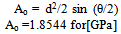 | (3) |
 | (4) |
3. Results and Discussions
- The XRD pattern of the initial synthesised nano-HAP powder, along with the XRD patterns of the HAP pellets sintered at temperatures of 650℃, 850℃, 1050℃ and 1250℃ for a period of 2 h are presented in Figure 2. All sample XRD patterns, except the 1250℃ one revealed the presence of crystalline nano-HAP phases.
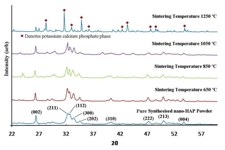 | Figure 2. XRD spectrum of synthesised nano-HAP powder and nano-HAP powders compressed at 70 MPa and thermally treated at various sintering temperatures |
|

 | (5) |
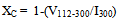 | (6) |
 | Figure 3. (a) FESEM of synthesised nano-HAP ultrafine powders; (b) a typical FESEM micrographs of an indentation produced on the surface of a pellet during the Vickers hardness test; (c) to (f) are FESEM micrographs of samples thermally treated at sintering temperatures: (c) 650 ºC; (d) 850 ºC; (e) 1050 ºC; and (f) 1250℃ |
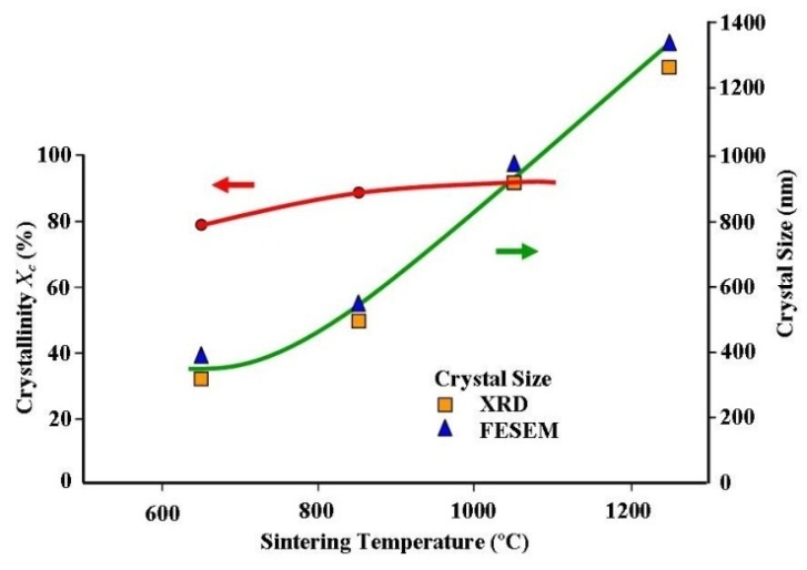 | Figure 4. Crystal size growth and increasing crystallinity with increasing sintering temperature |
 | Figure 5. The effect of increasing open porosity in the test pellets on Yield Strength and BET surface area |
 | Figure 6. The effect of sintering temperature on the open porosity and Vickers hardness of test pellets |
 | Figure 7. Fibroblast cells attaching onto the surface of a hydroxyapatite ceramic pellet made from n-HAP powders |
4. Conclusions
- Nano-crystalline nano-HAP powders composed of spherical 30±5 nm particles were formed under the influence ultrasound irradiation and then thermally treated using a conventional microwave oven. The powders were then compressed at 70 MPa to form pellets which were then sintered at sintered at temperatures ranging from 650 to 1250 ºC. The study confirmed that Vickers hardness significantly increased with increasing sintering temperature and density as the porosity decreased. Meanwhile, the yield strength of the ceramic pellets decreased as both the porosity and BET surface area increased. During the sintering process both the crystal size and crystallinity of the ceramics steadily increased with sintering temperature. Despite being advantageous, the reduction in matrix porosity to increase the yield strength of the ceramic for load bearing applications, the reduced porosity would significantly reduce cell migration and proliferation within the ceramic matrix. Hence, further work is needed to reach a compromise between porosity, strength and cellular integration potential of this nano-HAP derived ceramic for various biomedical applications.
ACKNOWLEDGEMENTS
- Dr Derek Fawcett would like to thank the Bill & Melinda Gates Foundation for their research fellowship. The authors would like to acknowledge the assistance of Prof. Arie Van Riessen and Mr. Zhenhua Luo in performing the hardness testing.