-
Paper Information
- Previous Paper
- Paper Submission
-
Journal Information
- About This Journal
- Editorial Board
- Current Issue
- Archive
- Author Guidelines
- Contact Us
American Journal of Biomedical Engineering
p-ISSN: 2163-1050 e-ISSN: 2163-1077
2012; 2(4): 189-196
doi: 10.5923/j.ajbe.20120204.07
Validation of Smart Garments for Physiological and Activity-Related Monitoring of Humans in Harsh Environment
Emanuele Lindo Secco 1, 2, Davide Curone 2, Alessandro Tognetti 3, Annalisa Bonfiglio 4, Giovanni Magenes 1, 2
1Department of Computer Engineering and Systems Science, University of Pavia, Pavia, 27100, Italy
2Innovation Technology Area, European Centre for Training and Research in Earthquake Engineering, Pavia, 27100, Italy
3Centro E. Piaggio, University of Pisa, Pisa, 56126, Italy
4Department of Electrical and Electronic Engineering, University of Cagliari, Cagliari, 09123, Italy
Correspondence to: Emanuele Lindo Secco , Department of Computer Engineering and Systems Science, University of Pavia, Pavia, 27100, Italy.
| Email: |  |
Copyright © 2012 Scientific & Academic Publishing. All Rights Reserved.
A set of garments capable of monitoring the physiological, activity-related and environmental parameters of emergency operators during their interventions was developed in a European Project called ProeTEX. This work reports the results of the field trials performed with the final prototype release at the APT international Fire Fighting Survival Training Centre in Italy. Four sessions of trials (warm-up, rescue intervention, outdoor fire-fighting intervention and smoky chamber route) were performed in harsh environment by 6 professional Fire-Fighters. The operators wore the ProeTEX prototypes and their Heart Rate (HR), Breathing Rate (BR), Body Temperature (BT), External Temperature (ET), Heat Flux (HF) and GPS speed have been acquired. Percentage of samples out of the physiological range (R%) of the HR, BR and BT, as well as percentage of samples showing high variability (V%) of the HR, BR, BT, ET and HF have been processed. Percentage of GPS samples showing artefacts of their ground speed (S%) have been also computed. The results on the HR, BR and BT signals showed a maximum R% of 2.0, 7.8 and 8.5 respectively, as well as a maximum V% of 14.0, 10.0, 0.2, respectively. Concerning the ET and HH data, a V% lower than 0.0 and 2.9, respectively, was found. Finally, the highest detected value of S% of the GPS speed was 3.5 in all the trials. On the whole these results showed the efficacy of the ProeTEX wearable system and its capability of real-time and continuously monitoring the rescuers while they perform even highly intense activities in harsh environmental conditions.
Keywords: Textile Sensors, Wearable Sensors, Smart Garments, Real-time Monitoring of Emergency Operators, Field Trials, Harsh Environment
Article Outline
1. Introduction
- On the last 10 years, dramatic events occurred over the world: the World Trade Centre attack in 2001, the Indian Ocean tsunami in 2004, the Haiti earthquake in 2010. During these disasters, several civilian people and rescuers, as well as large geographical areas, were involved: after these facts, the scientific community started to focus on the possibility of implementing new smart instruments that may improve the efficacy and capability of the operators’ interventions during terroristic and natural catastrophes. From an engineering viewpoint, novel technologies - for a more efficient monitoring and coordination of the emergency personnel - were investigated[1, 2]. In particular, thanks to the miniaturization and integration capability of electronic systems, the possi bility of developing ‘smart’ garments, gathering wearable sensors for the physiological, behavioral and environmental parameters monitoring[3] has emerged. These technologies were partially inherited from the military applications[4] and from the worker or explorer protection systems[5, 6]. In the present paper, we will focus on the results of the 4-years European projects called ProeTEX (Protection e-Textiles: Micro-Nano-Structured fibres systems for Emergency-Disaster Wear), aimed at developing smart garments - endowed with autonomous sensors, communication systems and data processing software - in order to support the intervention of emergency operators in harsh environments[7,8]. The ProeTEX project began in 2006 and involved 23 partners from 8 countries (including industries, research centres, laboratories and academic institutions[7]). The work-plan included 3 fabrication cycles, and each cycle was based on a 3-phases procedure: the definition of the requirements and specifications (1), the manufacturing of the prototypes (2) and finally the laboratory and field trials (3). Stages 1 and 3 were performed together with professional end-users (Italian and French Fire-Fighters). On the whole, 3 different versions of the prototypes were finally delivered: this paper deals with the performance of the final one; it is structured in 3 paragraphs: the description of the system - in terms of wearable components and information management strategy –, the protocols and results of the validation and, finally, the conclusion.
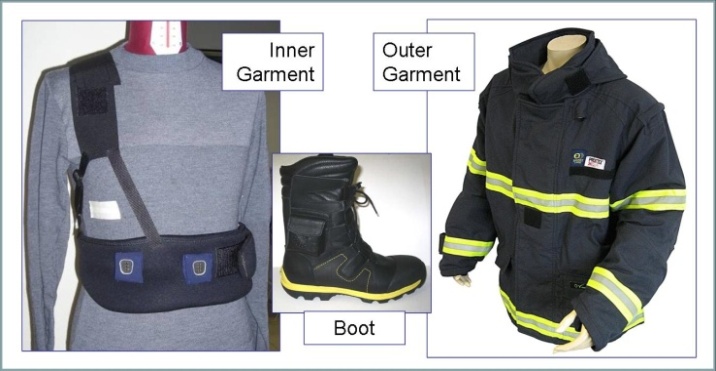 | Figure 1. The 3rd release of the ProeTEX Fire-Fighters prototype: the fireproof T-shirt or inner garment, the jacket or outer garment and the boots (on the left, right & central panel respectively) |
2. The ProeTEX Architecture
- The ProeTEX prototype basically consists of 3 wearable elements: a smart T-shirt - called the Inner Garment – that is directly in contact with the skin of the emergency operator; a jacket or Outer Garment and a pair of Boots (Figure 1).
2.1. The Wearable System
2.1.1. The Inner Garment (IG)
- The IG aims at monitoring the physiological parameters of the Fire-Fighter, thanks to a set of sensors in direct contact with the skin of the subject: in particular, the T-Shirt embeds an elastic region that contains textile sensors, whereas the electronics - supporting the sensors - is detachable and located within another textile band;this latter one surrounds the chest and is connected to the sensors through textile-conductive cables within the fabric; the band also contains a rechargeable battery – in order to power the system - plus a ZigBee (IEEE 802.15.4) wireless communication module - to transmit all data of the IG sensors out of the T-Shirt: the textile sensors provide the real-time Heart Rate (HR), Breathing Rate (BR) and Body Temperature (BT) of the subject. In Figure 1, left panel, the IG and the electronic band are shown: a complete description of the fabric textile composition and of the sensors’ functionality is reported in[8, 9]; in short, the HR signal is extracted by means of one ECG lead made of 3 textile knitted electrodes combined with a proprietary algorithm running within the electronics; the BR sensor employs a piezo-electric transducer in wire form and mounted within the band; it generates periodic signals - related with the chest movement - that are locally processed to extract the breathing rate. Finally, a digital BT sensor - thermally insulated towards the external environment - is located in a pocket at armpit level.
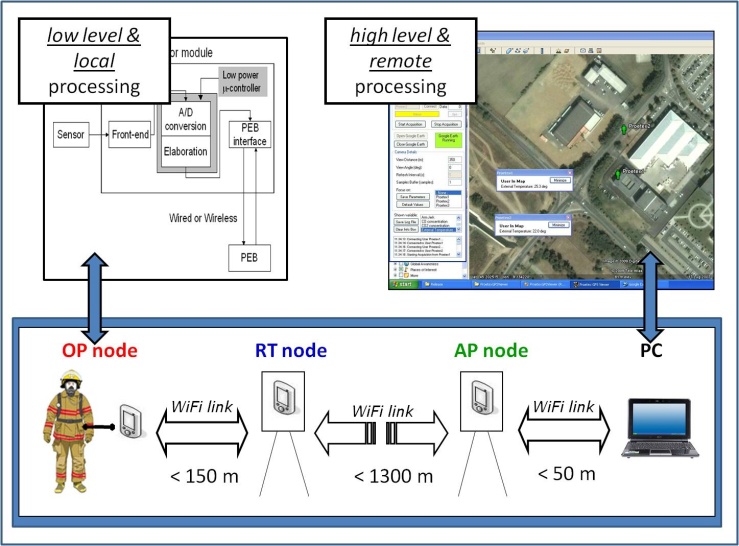 | Figure 2. The ProeTEX information management strategy (bottom panel): low level and high level information processing (on the top left and top right panel, respectively) |
2.1.2. The Outer Garment (OG)
- The OG aims at monitoring the operator activity and the surrounding environmental conditions; the OG equipment includes a couple of tri-AXial accelerometers (AXs), an External Temperature (ET) sensor, a Carbon monOxide (CO) sensor, acoustic and visual alarm modules, a Heat Flux (HF) sensor, and a GPS module. An electronic unit, called Professional Electronic Box (PEB) is embedded within the garment and it collects all the data coming from all the IG, OG and BO sensors; the PEB is also wired to an off-body radio transmission module combined with two textile antennas, and allowing the Wi-Fi (IEEE 802.11) wireless transmission of all the data set to a remote unit coordinating the intervention; the PEB is physically connected with all the OG sensors through a RS485 bus and it contains two Li-ion rechargeable batteries that assure the power supply of the whole network. In Figure 1, right panel, the whole OG set-up and sensors’ location are shown. Exhaustive details of the OG textile composition and sensor technologies have been already reported in[8, 9]: briefly, the ET and HF modules are positioned under an external layer and another thermally insulated layer respectively, at shoulder level; on the OG back side, the GPS module provides accurate geo-referenced position and ground speed of the subject while operating outdoor. A visual alarm module is positioned on the sleeve, in an easily visible location: the module is based on a power led driven by a microcontroller; an acoustic buzzer, is also integrated in the OG collar. For the external communication of the data, two textile antennas are located in the front and back sides of the OG, respectively: this double redundancy assures good communication quality, irrespective of the relative position and line of sight of the operator vs. the remote unit and vs. possible equipments on the operator’s shoulder like oxygen bottles, that may screen the radio signals. Since the CO is a toxic gas with a density comparable to the air, a CO-sensitive transducer is placed at lapel level, near the subject’s breathing ways (9). Finally, two AXs - aimed at detecting the head and wrist movements of the subject – are placed on the collar and sleeve of the OG, respectively (6).
2.1.3. The Boots (BO)
- On the boots there are two sensors - with their own power supply and ZigBee (IEEE 802.15.4) wireless communication module – that collect and wirelessly transmit the data to the PEB within the OG (Figure 1, central panel). The two sensors are a pressure transducer, based on an organic field effect transistor, for step frequency detection, and a carbon dioxide (CO2) sensor; compared with the CO sensor, the CO2 one is placed at ground level since the carbon dioxide is heavier than the carbon monoxide and it tends to accumulate at a lower level. More details and specifications on these sensors have been reported in[8, 9].
2.2. The Information Management Strategy
- In the paragraph 2.1 we presented a brief overview of the main characteristics of the ProeTEX IG, OG and BO sensors’ network (i.e. the Body Area Network, BAN). Here we focus on the strategy of managing all these information in terms of data processing, communication and visualization. The information management is a critical task since, at present, the emergency operators do not dispose of real-time physiological measurements, acceleration time patterns or GPS data; therefore it is essential to find a strategy for elaborating the raw sensors data in order to report more comprehensible features with an intrinsic and higher information content.
2.2.1. The Sensor Modules
- Form the very beginning of the project, a distributed intelligence architecture was adopted, at sensor level: therefore, each sensor module of the ProeTEX system contains the transducer, an analog front-end (if required) and a low-power microcontroller (see Figure 2, top left panel). This set-up allows the (a) real-time processing of the raw sensor data and the (b) extraction and communication of the relevant features. For example, the two AX modules sample the 3-axial accelerations at 100 Hz, then a TI-MSP430 microcontroller extracts in real-time the average trunk inclination, the intensity of the activity and the status (activity/inactivity) of the subject at 1 Hz; similarly, the hardware of the CO and CO2 modules samples each gas concentration and itautomatically launches an alert when predetermined warning thresholds are exceeded. Since each module is wired or wirelessly connected to the PEB, as a result, every 1 s all the IG, OG and BOs features are collected by the PEB and they are sent away to the coordinator of the operations by means of the communication system.
2.2.2. The Communication System
- The long-range communication system of ProeTEX manages the bi-directional data transmission between the PEB and the PC of the emergency coordinator PC (Figure 2, bottom panel): the plant is based on an extendible and portable Wi-Fi (IEEE 802.11) network that is based on 3 independent modules. Each module integrates the (a) rechargeable power supply (that allows more than 4 hours of autonomy), the (b) Wi-Fi LAN card and the (c) one-board PC (that implements the transmission services); all the parameters are broadcast from a module physically connected to the PEB, called the operator node (OP), to a bridge unit placed on a tripod at the edge of the intervention area (the retransmission node - RT). The RT unit, is provided with a directional antenna for the long-range communication (up to 1.3 km in open space condition) to a 3rd module, identical to the first one and wireless linked to the coordinator’s PC (the Access Point node - AP). An overview of this set-up is illustrated on the Figure 2, bottom panel; for more details on this architecture see also[10, 11].
2.2.3. The Remote Monitoring Software
- On the coordinator’s PC, a customized interface or Remote Monitoring Software (RMS)displays the GPS position of each ProeTEX equipment on a Google Earth map, and -on demand - all the sensor signals on a separated screen (see the top right panel of Figure 2). An intuitive convention of colours allows understanding the situation of each rescuer at a glance: the RMS automatically associates graphical green icons to all the operators having a regular status, whereas grey and red colours are associated to all the communication failures and warning status, respectively. A higher level of processing converts these singe-sensor warnings into global alarms related to the physiological, activity or environmental conditions respectively. The RMS allows saving all the data for post-processing analysis. More details on the RMS and the algorithms behind these multi-parameters warning detections are reported in[8-10] and[12, 13] respectively.
3. Field Trials
- As mentioned before, two types of tests have been performed on the prototypes: laboratory tests and field trials. In laboratory tests, the performances of the ProeTEX sensors were compared with the ones of golden standard instrumentations in properly and well defined environmental conditions. On the contrary, field trials were characterized by harsh and uncontrollable conditions, no highly constrained protocol and no reference instrumentations. Therefore, according to the nature of these tests, diverse quantitative and qualitative indexes of performance were used. On this work we only refer to the field trials; for more details on the laboratory tests please refer to[14-16].During the summer 2010, 4 sessions of field trials have been performed by 6 male professional Italian Fire-Fighters at the APT International Fire-Fighting Survival and rescue Training Centre in Bornasco, Italy[17]. Each session was performed at least 3 times by these operators while the wear the ProeTEX prototypes, with all the sensors activated. A questionnaire was delivered to the personnel at the end of all the tests, in order to receive their impressions and feedbacks concerning how much similar and difficult were the performed trials compared with the real interventions.The assessment of the ProeTEX device was performed in terms of the stability of each sensor signal during the time and its likelihood with respect to reasonably expected values. Precisely, the following reliability indexes were considered for each measurement:Heart Rate - Percentage of HR samples out of the physiological range (R%): the Number Of Samples (NOS) showing values higher than 200 beats per minute (bpm) and lower than 50 bpm, divided by the NOS of the acquisition (i.e. a low percentage means high reliability). Percentage of samples showing high variability (V%): the NOS showing a difference, with respect to its average in the previous 60 s, higher than 1 standard deviation (std) of the signal, divided by the samples’ number (since HR varies with an enough slow dynamic, a high percentage denotes artefacts, due to the subject’s movements or sensor failures).Breathing Rate - Percentage of BR samples out of the physiological range (R%): the NOS with value higher than 50 cycles per minute (cpm) or lower than 8 cpm, divided by the NOS (i.e. a low percentage of outliers implies a good reliability). Percentage of samples showing high variability (V%): the NOS showing a difference, with respect to the average of the signal in the previous 60 s, that is higher than 1 std of the signal, and divided by the NOS of the acquisition.Body Temperature - Percentage of BT samples outside the physiological range (R%): the NOS with value higher than 41°C or lower than 36°C divided by the samples’ number. Percentage of samples showing high variability (V%): the NOS whose difference with respect to the previous one is higher than 1°C (corresponding to a maximum accepted variability of 1°C/s), divided by the samples’ number (i.e. according to the natural body temperature dynamics, these values can be reasonably considered as artefacts, due to temporary sensor failures).External Temperature - Percentage of ET samples showing high variability (V%): the NOS whose difference with respect to the previous one is higher than 1°C, divided by the samples’ number (i.e. values respecting this condition are presumably artefacts leaded by sensor’s failures).Heat Flux - Percentage of HF samples showing high variability V%): the NOS whose difference with respect to the previous one is higher than 5 W/m2, divided by the samples’ number in the acquisition.GPS - Percentage of GPS samples, during outdoor experiments, showing a speed higher than 4 m/s (∼ 14Km/h) - S%: on the trials, the operators performed walking at an estimated speed certainly lower than 5 Km/h; therefore speed values higher than this threshold can be reasonably considered as artefacts.
3.1. Test 1: Warm-up
- The 1st test was conceived as an acquaintance phase allowing the operators to familiarize with the ProeTEX equipment and garments; the Fire-Fighters executed the test individually, performing the following sequence of activities: upright standing for 1 minute (min); walking outdoor on a defined path twice; upright standing for 2 min; walking once more on the same path by carrying a 36 kg load (i.e. 2 filled extinguishers); finally, upright standing for 1 min.
3.2. Test 2: Rescue Intervention
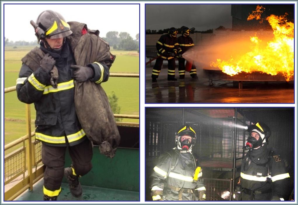
- On the 2nd test an indoor rescue intervention inside a 3 storeys building was simulated. At the beginning of the test, the operator was standing far away from the building; then he was asked to approach the edifice, climb the external stairs, get inside the structure from the roof and rescue a 15 kg manikin located at ground level. Then, the operator had to go back to the roof by carrying on the manikin. Figure 3 (left panel) shows this latter phase when the Fire-Fighter exits the trapdoor on the roof with the manikin placed on his shoulder.
3.3. Test 3: Outdoor Fire-fighting Intervention
- This third trial was carried out in an outdoor square, where a 4x4 meters wide tank, containing water and flammable liquids, was set on fire; the tank was also fed by gas pipes remotely controlled by the APT personnel and allowing the fire maintenance for an arbitrary lapse of time. Once the fire was set up, groups of 2 Fire-Fighters were asked to prepare one portable extinguisher and one fire-hose, walk towards the fire (up to few meters from the tank), and rest for few minutes in front of the fire at a safe distance; then it was requested to carry out a fire-fighting activity for some more minutes (see the top right panel of the Figure 3) and, finally, to rest near the fire and sort out all the equipments.
3.4. Test 4: Smoky Chamber Route
- After these three outdoor tests, the 4th one was executed indoor, in a chamber: groups of 2 operators were asked to move within a forced route inside multiple cages. The cages’ constraint obliged the rescuers to move on hands and knees at least in one part of the route. To increase the realism and simulate a smoky exploration of buildings on fire, the chamber was filled with non-toxic smoke. Subjects were also equipped with external breathing apparatus, according to the current practice of intervention on this scenario.
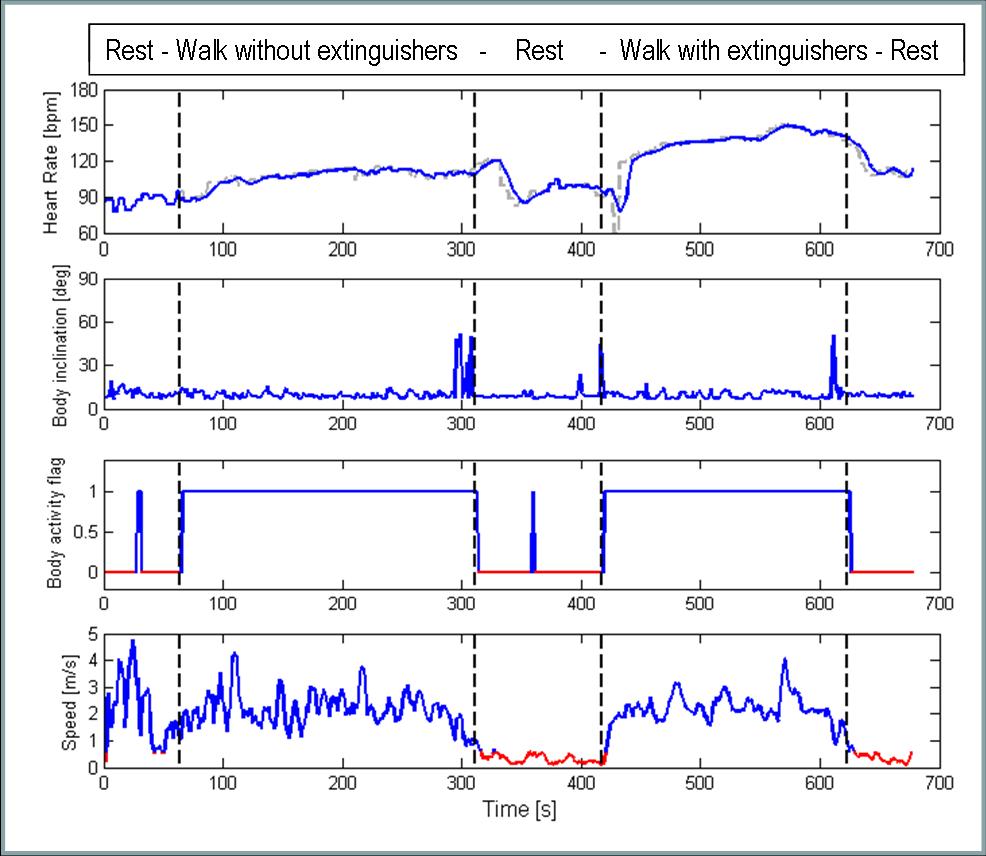 | Figure 4. Time plots of some ProeTEX sensors during the test 1 - warm-up. From the top to the bottom panel, the HR, trunk inclination, body activity and GPS ground speed, respectively |
4. Results
4.1. Fire-Fighters Evaluation of the Tests
- Table 1 reports the results of the questionnaire filled by the operators at the end of the tests. It regards the intensity, difficulty and similarity of the 4 tests compared to a real intervention: each evaluation is provided in a scale ranging between 1 (null intensity, difficulty and no similarity compared to a real intervention) and 10 (very high intensity, difficulty and high similitude with a real operation). As it was expected, the scoring of the first test was low, both in terms of physical intensity and difficulty (see the 1st column of the table); on the contrary, the 2nd test was perceived as a little bit more intense and similar to a real intervention (2nd column). A maximum level of intensity was reached with the 3rd test, whereas the 4th one reached the top of similarity (3rd and 4th columns respectively).
|
4.2. Sensors Performance Assessment
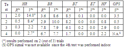
- Table 2 reports the performance of each ProeTEX sensor, according to the criteria detailed in the par. 3. Figures 4 and 5 report the time patterns of some sensor signals during tests 1 and 3, respectively. A test by test discussion of the results follows below.
4.2.1. Test 1 – Warm-up
- The first test was thought as a succession of resting and active stages, in order to allow the recognition of the signals belonging to the different phases and detect the typical dynamics – associated to these transitions of activity - of the physiological parameters: an HR increase and decrease were noticed when the operators carried on the load and rested respectively (see the 1st plot on the top of the figure); however, the physical effort was of little importance, since the resting HR was rapidly recovered at the end of the walking. From a postural viewpoint, the plot of the trunk inclination – i.e. the feature extracted from the collar AX module signals, 2nd graph from the top - tells us that the operator was upright standing during quite all the test on this phase (and this was visually verified). During the 3 different trials, the average inclination angle was equal to 10.1°, 12.2° and 11.5°, respectively1. The AX modules detected also the type of the subjects’ activity: no false inactivity alarms were observed (2nd graph), as well as the resting and moving phases were clearly identifiable from the history of the collar AX flag (3rd graph)2; remarkably, this latter plot was highly correlated with the one of the GPS ground speed (4th graph).According to the criteria in par. 3, the HR sensor performance was fine in 2 (out of 3) trials: 2.0% of the HR samples were erroneous, and 14.0% of them showed an abnormal variability (see the values of R% and V% on the Table 2, 1st line). A good BR performance was noticed over all the 3 trials, since only the 3.6% of the samples were manifestly wrong and 8.6% exhibited a high variability. The BT sensor displayed 8.5% and 0.1% of unreliable and high variability samples respectively: these anomalies are related to the detection of a body temperature lower than 36.0°C at the beginning of the test and can be easily explained, since the T-shirt was previously undressed and the sensor required about 15 min to reach a steady state. No failure were noticed on the ET, HF and CO sensors: an ET close to the actual temperature was found (∼ 25°C), and the CO sensor correctly indicated a concentration of 0 ppm (part per million); the HF returned slightly negative values, even if close to zero (i.e. a low heat flux flowing out from the body to the external environment).The GPS module required a warm-up period of about 180 s, that was compatible with the sensor’s specifications (i.e. 3.5% of the samples showed an anomalous speed); a ground speed signal was real-time derived by the RMS, given the GPS longitude and latitude values: remarkably, the phases of resting were clearly distinguishable from the ones of walking just by setting – via software - an 0.5 m/s threshold on the GPS ground speed (see the red line on the 4th graph of the Figure 4).
4.2.2. Test 2 – rescue intervention
- This experiment aimed at assessing the physiological sensors’ performance – and of the HR and BR modules in particular - when the users performed activities - like moving the arms while climbing ladders or carrying the manikin on the shoulders - that could in principle interfere with the behavior of the ProeTEX electronics.High quality HR results were observed in 2 (out of 3) trials, with 0.5% and 8.4% of wrong and high variability samples respectively (see the values of R% and V% in the Table 2, 2nd line); in general, the HR sensor produced reliable signals even during unusual arm and trunk movements; the quality of the signal allowed discriminating between resting phases (i.e. descending or stable HR pattern) and intense physical activities (i.e. increasing HR pattern). These performances were probably favoured by the fact that operators worn their garments for enough time before the test, allowing a little sweating that improved the skin-electrodes contact. Concerning the results of the BR module, only 2.9% of the samples were unacceptable and 10.0% exhibited a high variability: the intensity of the activities did not affect the signal quality at all. Similarly, the BT data presented unreliable values on 8.2% of samples only, with no oscillations (0.0%).
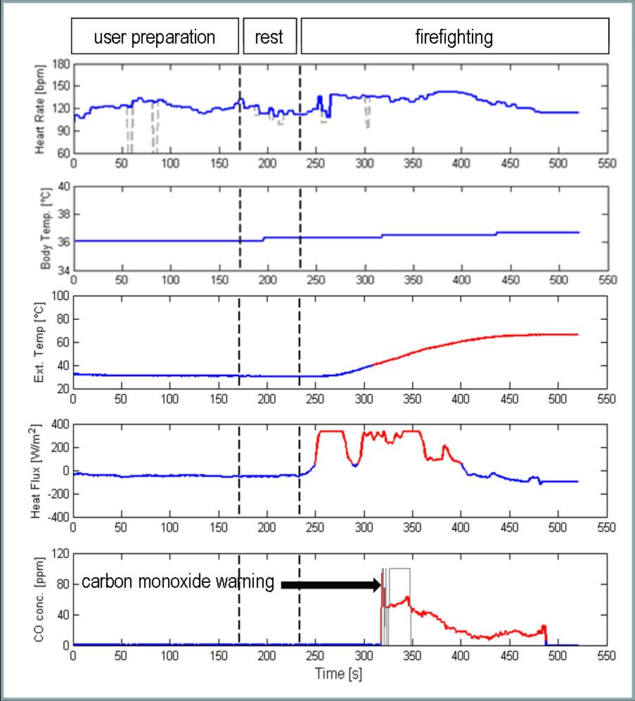 | Figure 5. Time plots of the ProeTEX sensors during the test 3 - outdoor fire-fighting intervention: from the top to the bottom panel, the HR, BT, ET, HF and CO concentration, respectively |
|
4.2.3. Test 3 – outdoor Fire-fighting Intervention
- This trial aimed at investigating the prototype functionality in harsh conditions with a special focus on the subsystems devoted to the environmental monitoring (i.e. the ET, HF and CO modules). According to the plots of Figure 5, the test was not extremely intense, since the HR was quite steady and did not show high peaks (1st plot). In terms of thermal stress, the BT was lower than 37°C and did not increase when the user was approaching the fire; in contrast, the ET values grew up to 60°C and a positive HF trend (i.e. meaning that the flux was entering the body) activated a warning alert (see the 3rd and 4th plots of the figure). Although these type of tests were executed outdoor, the CO sensor detected non zero concentration values, in the range of 40-80 ppm: in fact, an alert was launched at 50 ppm (see the red line of the 5th plot), according to a pre-programmed set-up within the firmware of the CO module; this is a reasonable threshold value, according to the limits of long-term workplace exposure established by the OSHA (Occupational Safety and Health Admistration) in the U.S. Finally, regarding the performance indexes, 0.3% and 2.2% of the HR samples were erroneous and showed an abnormal variability (see the values of R% and V% in the Table 2, 3rd line); since these results were obtained after wearing the garments for a long time, they support the fact that the quality of the HR signal was not significantly affected by an extended usage of the garments.The BR sensor performance was also satisfactory: the module never stopped working and produced reliable values during all trials, a part from some isolated spikes on less than 10% of the data, with abnormal readings and high variability on 7.8% and 7.9% of the data respectively. Artefacts and unreliable samples of the BT sensor occurred only in the 0.2% and 6.1% of cases, respectively; the BT values normally ranged from 36°C to 37 °C: some picks of values higher than 38°C were noticed during the exposure to the fire. In 2 tests (out of 3) the trunk AX worked correctly (both in terms of inclination angle and activity flag), whereas the wrist AX performed well during all trials. The ET module sensed maximum temperatures in a range of 60÷75°C at the beginning of the fire-fighting procedure, while the operators were approaching the flames (see the Figure 3, top right panel); since this sensor module is placed between an external layer of the jacket and another fireproof internal layer, the measure was not affected by any radiation; however, a delay of about 60 s was noticed between the fire exposure and the increase of the recorded temperature; conversely, the HF transducer exhibited a faster response (see the 3rd plot vs. the 4th one, Figure 3) and less than 1.0% of the samples showed an abnormal variability. To finish, no remarks were imputable to the GPS module, whose performance was faultless (GPS S% = 0.0, see the 3rd line of Table 2).
4.2.4. Test 4 – Smoky Chamber Route
- The last experiment aimed at testing the prototype performance - and especially those of the physiological sensors - in quite critical (for the system) conditions due to: § the lying down postures of the subjects, that, for instance, are a possible cause of temporary detachments of the HR electrodes from the skin of the operator;§ the use of external breathing apparatus, whose belts passed over the ProeTEX electronics (see the Figure 3, bottom right panel).Despite the crouched posture and use of the breathing apparatus, the HR signal quality was acceptable in 2 (out of 3) trials with no unreliable values (R% = 0.0%, see the Table 2, 4th line) and few oscillations (V% = 2.7%); on the other side, during one trial the HR signal was available each time the subject was upright, with a good quality of the signal during the motionless stages only: these unsatisfactory results were interpreted by a wrong fitting of the T-Shirt with the operator body (i.e. the T-shirt was not tight enough). Regarding the BR subsystem, only 6.7% of samples were unreliable and 7.7% presented irregular variability (especially during the crouched movement’s executions); no significant interferences, between the breathing apparatus belts, the air bottles and the piezoelectric sensor, were noticed. The BT signal was coherent during all the trials (1.7% and 0.0% of unreliable and high variability samples respectively), and the temperatures were reasonably measured in a range between 36.5 and 37.5°C: moreover these values were stable, since the subjects wore (and warmed) the IGs for some time before performing the test. The AX modules did not show any malfunctioning and the trunk inclination angles allowed discriminating between the upright and crouched postures properly; similarly, the activity flags permitted to discriminate phases of resting from the explorations, when the operators moved on their hands and knees within the cages. Finally both the ET and HF systems worked properly too (0.0% and 2.2% of high variability samples, respectively); concerning the GPS signal, it was unavailable, since the test was performed indoor; the CO unit returned a gas concentration around 0 ppm, since a non toxic (CO free) artificial smoke was used during the experiment.
5. Conclusions
- This paper presents the results of the field trials performed with the final release of the Fire-Fighters ProeTEX prototypes, at the APT Training Centre, in 2010. The outcome of these trials showed that the ProeTEX architecture represents a unique and reliable set of garments for the real-time monitoring of physiological, environmental and activity-related parameters of the rescuers while performing their interventions. Remarkably the system is capable of a continuous and reliable functioning even when the operators perform emergency actions characterized by intense movements in an environment with high temperature and heat flux.Although the ProeTEX project was finished in 2010, we expect these prototypes to be known and used by emergency operators out of the research context and community. To this aim, the whole ProeTEX equipment - or, at least, a portion of that - may be used during the training and preparation courses of the emergency operators. Later, this use could be extended to the real operations and interventions, provided that the prototypes will have complied with the security standards and rules belonging to each country. It is also essential to remark that the ProeTEX prototypes are introducing the real-time measurements of variables that were unavailable in an emergency context before this project: therefore the availability of these data may pioneer a new set of criteria or way of evaluating the training procedure and actions under an intervention, according to the measurable feedback returned by the ProeTEX sensors.
ACKNOWLEDGEMENTS
- The authors want to thank the Italian Fire-Fighter teams of Pavia & Mortara, as well as the personnel of the APT Training Centre for their valuable support and participation in the trials. The European Commission is gratefully acknowledged for funding this activity under the project ProeTEX (ICT, VI FP, contract # 26987).
Notes
- 1. According to ProeTEX sensor convention, a trunk inclination angle of 0° and 90° corresponds to upright and lying posture, respectively.2. Activity flag equals to 0 and 1 means motionless and moving trunk of the subject, respectively.
 Abstract
 Reference
 Full-Text PDF
 Full-Text HTML