-
Paper Information
- Next Paper
- Previous Paper
- Paper Submission
-
Journal Information
- About This Journal
- Editorial Board
- Current Issue
- Archive
- Author Guidelines
- Contact Us
American Journal of Biomedical Engineering
p-ISSN: 2163-1050 e-ISSN: 2163-1077
2012; 2(2): 38-40
doi: 10.5923/j.ajbe.20120202.07
Electronic Cough Monitor
 Abstract
 Reference
 Full-Text PDF
 Full-Text HTML
Musaab Hassan 1, Asiel Satti 2, Azza Hussien 2, Tarteel Tag El-Din 2
1Department of Mechanical Engineering, Faculty of Engineering, Sudan University of Sciences and Technology, Southern Campus, Khartoum, Sudan
2Department of Biomedical Engineering, Faculty of Engineering, University of Medical Sciences and Technology, P.O. Box 12810, Khartoum, Sudan
Correspondence to: Musaab Hassan , Department of Mechanical Engineering, Faculty of Engineering, Sudan University of Sciences and Technology, Southern Campus, Khartoum, Sudan.
| Email: |  |
Copyright © 2012 Scientific & Academic Publishing. All Rights Reserved.
Cough is an important symptom to consider when diagnosing diseases. Hence, information about level as well as the rate of cough could be very useful for physicians. In this work, a cough monitoring system was designed. The designed system was capable of recording only cough sounds using appropriate circuit. The circuit utilizes a simple transducer (unidirectional microphone). An LED (light emitting diode) was caused to light every time a cough sound is detected. The design was also accompanied with a programmed alarm (using ATmega8535L) if the number of coughs exceeds certain number.
Keywords: Cough, Signal, Band Pass Filter, Microcontroller, Electronic Display
Article Outline
1. Introduction
- In medical field, cough is defined as a repetitive, spasmodic contraction of the thoracic cavity, resulting in violent release of air from the lungs, and usually accompanied by a distinctive sound[1]. As air being sucked in or forced out, these passages may get obstructed by a small object or inflammation which results in the cough reflex that helps to clear the obstacle[2]. Acute cough lasts for 3 weeks or less; its most frequent cause is the common cold, but occasionally, acute cough can be due to a more serious illness such as pneumonia or congestive heart failure[3, 4]. Methods and techniques used previously for cough signal detection include; detection of vibration created by coughs using an accelerometer, applying electromyogram (EMG) leads over the chest wall for detection of sound and electrical signal respectively, and using a cardio-respiratory monitoring system and an integrated unidirectional contact microphone for signal pick-up[5-13]. In this work, authors detected the cough sound using microphone and the signal was processed for monitoring purpose. Two different techniques were applied; the first one was based on designing a bandpass filter while the second technique incorporated a microcontroller. Both designs are discussed in the following section.
2. Proposed Cough Monitoring System Based on Band-Pass Filter
- This proposed design includes a pick-up part, the processing part and output part. Figure.1 illustrates the layout of the monitoring system. The pick-up part includes a transducer and preamplifier to convert the cough sound to electrical signal and amplify it respectively. The processing part includes filter, high gain amplifier and analogue to digital converter. The output part includes alarm system and display. The band-pass filter was divided into two parts; a high pass filter (HPF) which should pass frequencies greater than 30Hz, and a low pass filter (LPF) which should pass frequencies below 100Hz.Both filters have capacitors as well as resistors. The capacitor value was chosen to be 1 µF and the resistors values were calculated accordingly as follows;
 | (1) |
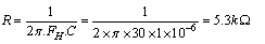 | (2) |
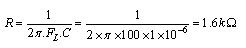 | (3) |
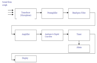 | Figure 1. Proposed Cough monitoring system based on Band-pass filter |
 | Figure 2. Proposed Cough monitoring system based on Microcontroller |
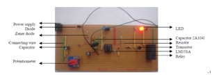 | Figure 3. Picture of the circuit board (part.1: pickup board) |
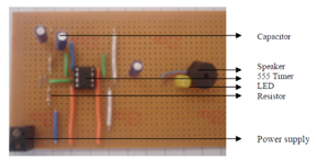 | Figure 4. Picture of the circuit board (part.2: alarm board) |
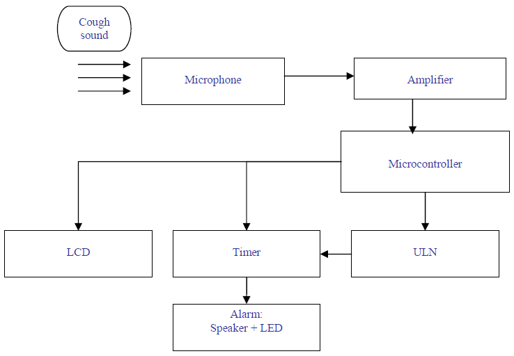
3. Proposed Cough Monitoring System Based on Microcontroller
- This proposed design is shown in Figure.2. Sound is picked up by the microphone and fed to the op-amp. This is connected as a non-inverting amplifier with a gain of 151 or +43.6dB. The 100pF capacitor across the 150K feedback resistor rolls off the high frequency response above 10 kHz to eliminate noise. The connection are shown in figures 3 and4. The output at pin.1 feeds two diodes, which function as half-wave voltage rectifiers. These rectify the sound signal to produce a DC voltage across the 2.2 µF, which is directly proportional to the input sound level. This DC voltage is fed to pin 5 the second op-amp. This is connected as a comparator. A resistive voltage divider applied about 2V to pin 6. Once the DC voltage across the 2.2 µF rises above the voltage at pin 6, pin 7 sets high. This turns on transistor Q1 that activates the relay and turns on the LED. Q1 remains on while the DC voltage at pin 5 is above that at pin 6. However, the release time takes about 3 seconds determined by the time constant of 2A104J capacitor, 1M resistor and the pin 6-threshold voltage. A diode is connected across the relay to protect Q1 when the relay turns off (back-e.m.f). For circuit protection from inversely connected power, a 1N4002 diode is connected in the first part of the circuit. The microphone sensitivity may be varied with the 200 kΩ potentiometer. If more sensitivity is needed then turn the potentiometer to maximum sensitivity clockwise). The output from the relay in the pick-up board is fed to port A of the microcontroller. After the use of the port to enter the signal the port is put to ground for the microcontroller protection through a pull up resistor connected to ground. In port A the signal is sampled and converted to a digital signal because the port can function as an analogue to digital converter. Now, the digital signal will be sent to two different areas, the first to a ULN chip which amplifies the current of the signal up to 300 mA to be used in the alarm circuit. The second is that the signal will be entered to a software program that measures its amplitude and counts it. According to the results of the software the readings will be sent through port B to the LCD, a potentiometer is connected to the LCD through pin 3 to adjust its contrast. The microcontroller has an external oscillator crystal connected to pins 12 and 13 to increase its operating frequency from 1 MHz to 8 MHz. The amplified current from the ULN is passed to the alarm circuit to operate it in one case only; the number of coughs exceeds a certain number specified in the software, if this number is exceeded the microcontroller passes a signal to the ULN to trigger the alarm circuit. The alarm circuit has three capacitors, two of the value 1micro F to block the DC offset and the other to control the timing interval of the timer. The third capacitor has value of 10 µF, which functions to interrupt the alarm and reset it back to zero volts after the time interval is passed.
4. Result & Discussion
- The two proposed systems, the band-pass filter and microcontroller based monitoring systems, were tested. The detected cough signals were measure, saved and analyzed.Output signal from a pick-up and amplification circuit obtained from the filter design was very noisy as it can be seen in Figure.5. The modified design, incorporating microcontroller, gave a better results.
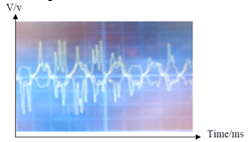 | Figure 5. Output of pick-up circuit with coughing (5v/div-10ms/div, Vpp=28volts and f=100HZ) |
|
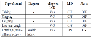
5. Conclusions
- The sound of a cough was successfully detected electronically. The designed circuit was capable of differentiating between the sound of cough and other sounds with high precision (e.g. laugh, clapping, talking). LCD displays the level of cough in voltages. LED as well the alarm operate whenever the number of cough sounds detected exceeded ten. This system could be very useful for physicians for diagnosis of cough related diseases. This system, if not being used alone for diagnosing purpose, can be part of a system to diagnose diseases electronically.