Selcuk Helhel 1, 2, Zeynep Akin Colak 1, Sukru Ozen 1, 2
1Akdeniz University, Engineering Faculty, Electrical and Electronics Engineering, Antalya, TR
2Akdeniz Univ., Industrial and Medical Based Microwave R&D Centre (EMUMAM), Antalya, TR
Correspondence to: Selcuk Helhel , Akdeniz University, Engineering Faculty, Electrical and Electronics Engineering, Antalya, TR.
| Email: |  |
Copyright © 2012 Scientific & Academic Publishing. All Rights Reserved.
Abstract
60 Million mobile phone holders in the country forces clinics and cellular phones have been started to be in concern as an electromagnetic interference (EMI) source in hospitals. Hospital buildings are very huge buildings that they are not allowing deep radio penetration through the hole those results in higher uplink power transmission (2W of maximum). These two reasons were our motivation to make an investigation to examine the EMI issues surrounding medical equipment, due to interference from communication devices, including GSM900, GSM1800, and 3G digital mobile phones. Electromagnetic interference, particularly of the ECG and ted EEG device was observed, and exposure begins within the range of 1.25m. It has been observed that uplink power is not a reason of interference itself, but the locations of mobiles and health care units are also the reason of interference.
Keywords:
Electromagnetic Interference, 2G-3G Mobile Services, Medical Devices, ECG Recording, Clinics
Cite this paper:
Selcuk Helhel , Zeynep Akin Colak , Sukru Ozen , "Distance and Location of Both Mobile Phones and Health Care Units: Determines the Interference Level", American Journal of Biomedical Engineering, Vol. 1 No. 2, 2011, pp. 78-82. doi: 10.5923/j.ajbe.20110102.14.
1. Introduction
ECG type monitoring equipments are used attached with patient’s body for long term recording. ECG type equipments record continuous data belongs to patient to observe vital signs. Those equipments are generally categorized in life-support equipments, since a malfunction could have serious consequences. Physiological signal outputs are normally very weak and requiring sensitive receiving devices in order to process them. These sensitive receivers are vulnerable to Radio Frequency Interference (RFI). For such devices used in clinics to gather data, interference is an important problem for analyzing signals.Medical equipments are expected to make correct recordings related to patients’ problems. It has been reported[1,2] that mobile phones are interfering recordings and results incorrect data collection which is well known that any electromagnetic source[3] can harm electronic equipments as well as the living[4]. Mobile phones are very important interfering sources especially in the area having poor coverage (low signal level, <-90dBm). Interference risks caused by mobiles phones were analyzed at different studies[5-8] in the past.Tang et al.[8] reported radio-frequency susceptibility test on medical equipments in Canada in 1994 that ventilators, infusion pumps, defibrillators with an ECG monitor, andfetal monitors had been found to be quite susceptible to EMI. Reported study was suggesting that care should be taken when operating very high frequency (VHF) radios, ultrahigh-frequency (UHF) radio, and cellular phones within 1 m of these devices. The Medicines and Healthcare Products Regulatory Agency (MHRA) in the U.K. carried out an EMI test on medical equipment using different mobile communication devices had shown that anesthesia machines, respirators, external pacemakers, ECG monitors, defibrillators, infusion pumps, and ventilators were also sensitive to EMI[9,10].Tang et al[8] studied on interfering capability of 2G and 3G mobile systems on medical equipments and showed that medical equipments were more sensitive to 2G systems then 3G systems. They showed that an ultrasonic fetal detector is the only equipment sensitive to 3G mobiles.In present study, measurements were carried out in The Medical School Hospital of Akdeniz University in Antalya. TEMS Cell setup was used as an interfering source in order to obtain maximum uplink power which allows doing this. Details of measurement setup are given in[11]. Different medical equipments at different departments have been selected to investigate electromagnetic immunity, and repeated equipments at different departments have not been re-counted, but had been measured for any possibilities
2. Measurement Environment and Methodology
GSM and PCS systems are operating at 900MHz and 1800MHz, respectively. They are using 50 different radio channels each having 200kHz bandwidth. One radio frequency is divided into 8 slots, and each slot is dedicated for one talk. During communication the radio equipments control each radio frequency in order to decide how much power they have to serve. 3G systems basically use wider bandwidth, and serving less power at about noise level[12]. 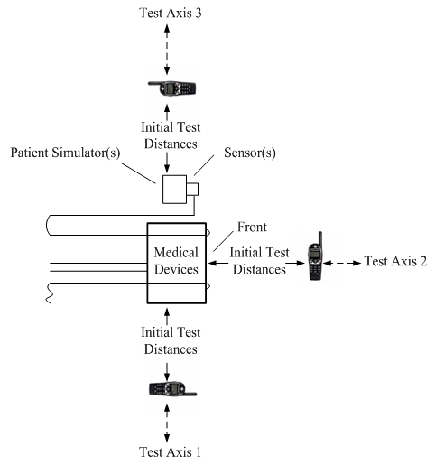 | Figure 1. Test set-up (ANSI C63.18[13]) |
Controlling the RF power output power of radios is one of the fundamental optimization steps for avoiding interfering sources. Systems are calculating and trying to balance both Ms (mobile phone) based signals with Bs (base station) based signals. This phenomena is called as link budget calculation, and ms based signal level is named as uplink power and Bs based signal level is called as uplink power. While base station signals are approaching mobile phones, mobile phones are automatically adjusting its output power (uplink power) for balancing both uplink and downlink losses[12]. This rule says that there is only one possibility in order to obtain higher uplink power that the area should be served by Bs signals of -90dBm or weak. There are also special test phones such as Ericsson TEMSCELL which allows to camp on desired long distance base station channels[11]. This study was carried out in Akdeniz University Medical School Hospital as a real environment in which patients had possibilities to use their mobiles. During study no special arrangements were done as Tank et al[8] did. For each room and equipment, possible test distances of those determined by ANSI C63.18[13] were tried.A control room was designed in the department[14] for 3D electromagnetic field distributions for analyzing the affect of location of both mobile phone and health care; a mobile test unit consists of two main parts: Andrew transmitter and Nokia N95 with FieldTest software. Andrew Test Transmitter is a small, low-power transmitter that can radiate GSM or WCDMA test signal. Test transmitter connects to a GSM indoor antenna with feeder cable. The required signal level and frequency can be adjusted in the range of test transmitter via Ethernet or Wi-Fi. Mobile phone is simply used for measuring the received signal at the points. To avoid interference, Absolute Radio Frequency Channel Number (ARFCN) 56 and 599 were used which are guard and unused frequencies in Turkey. Test unit having 2W output power was located at the centre of 4m wide, 7m length and 3m height office as shown in Fig.2. The level of 140cm above floor was chosen that it equals to the height of medical equipments’ positions in the hospitals. At this level, 4x7=28 positions were chosen in order to record data in 1mx1m resolution in the offices. At each positions, x, y and z-components of electromagnetic field distribution have been recorded.
3. Transmission Line Excitation by External Electromagnetic Fields
A non uniform electromagnetic field incident on a two conductor transmission line is shown in Fig.2.  and
and  are the electric and magnetic field components of incident electromagnetic field in the figure. The parameters L, d,
  ,
, and
and are the line length, separation distance between two lines, and characteristic, left hand and right hand load impedances, respectively.
 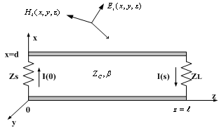 | Figure 2. A non-uniform electromagnetic field incident on a two-wire transmission line |
I(0) is the current in the left-hand load, and I(s) is the current in the right-hand load. The voltage read on loads are given as below,  | (1) |
 | (2) |
The incident field components induce distributed voltage sources along the wires and along the terminations that those voltage drops may harm the electronics. The electric field component  and
and  induce both a common-mode and a differential-mode current on the conductors. The common-mode current distribution is zero at both ends of the line; the common-mode currents do not flow in the load impedances. But, the differential- mode currents flow in the loads and only differential- mode currents are predicted by transmission line theory. A typical problem is the calculation of voltages induced on interconnects subject to incident plane waves. There are three equivalent formulations to this problem[15,16]. A complete treatment for different types of incident field may be found in the literature[15,17]. The induced current at the two terminations of a line subject to end-fire excitation for plane wave excitation is shown as an example.
 | (3) |
 | (4) |
Where, E0 is the magnitude incident electric field and  | (5) |
The incident field in the vicinity of the line may be produced by some distant antenna. These incidence fields in the vicinity of the line can then be determined by using the Friis transmission equation. The incident electric field produced by an antenna is | (6) |
Where PT is the radiated power, G is the gain in the direction of the line; incident magnetic field is given as below | (7) |
where  is intrinsic impedance of free space.
4. Results and Conclusions
TEMS measurement equipment[11], was used during this study. Tank et al[8] reported in their study that “-The highest transmission power of the mobile phone inside an individual assessment location, which is specifically determined by measuring the base station signal strength in different channels, is used to demonstrate the worst-case scenarios of interference for the medical equipment in that environment. The channel with the weakest base station signal strength is then selected for the immunity assessment.”, and their reported cumulative distribution of mobile phone base station signal strength received in the on-site immunity test is between -10dBm and -65dBm which is not realistic. That much of signal level will never force mobile phones to drive its maximum power, so that those figures are controversial.Health care unit measurements were carried out at intensive care unit with the Spacelabs-HealthCare and Ultraview SL type patient’s monitor, at pectoral surgery with the equipment of Abbott Plum A+ type serum device, at new born unit with Siemens SC 6002XL, at dialysis unit with Kawasumu dialysis equipment, at gynecology unit with Sony LOGIQ 5 PRO ultrasonic sensor, non-stress test equipment HP 50xm NST, at radiology department with Toshiba OC-12MB-1 type X-ray imaging, at pectoral unit with Fresenius Vial perfuser (injector), at children’s emergency unit with Nihon Kohden Life care 5000 type patient’s monitor, and at neurology unit with Medelek Synergy Electro Miogram. With repeated measurements for above units, no disturbances were obtained. At children’s EEG unit, downlink signal levels were so weak that mobiles were not camping on any frequency, that’s why call setup was established at corridor and moved to unit. At effort unit, a distortion on Cardio fax equipment was obtained at 1.25m distance of GSM and at 1m distance of 3G systems. For this unit and, 0.5m can be defined as the approaching distance. Table 1 demonstrates the distorted equipments with signal levels belong to 2G and 3G systems at critical levels.| Table 1. Critical Distance Table of EMG at GSM 900 |
| | Unit | Brand | UL(uplink)(dBm) | DL(downlink)(dBm) | CriticalDistance | | Effort | Cardiofax | 5 | -92 | 1.25 | | Cardio-vascular Unit | ECG9020K | 15 | -89 | 0.5 |
|
|
| Table 2. Critical Distance Table of EMG at 3G systems |
| | Unit | Brand | UL(uplink)(dBm) | DL(downlink)(dBm) | CriticalDistance | | Effort | Cardiofax | 5 | -100 | 1 | | Cardio-vascular Unit | ECG9020K | 7 | -79 | 0.4 |
|
|
| Table 3. Measurement Details |
| | Item No | Equipment | Affected | Source | Interfering Distance | | 1 | Cardiofax (Effort-1 Unit) | yes | 2G / 3G | 1.25m / 1m | | 2 | ECG | yes | 2G / 3G | 0.5m / 0.4m | | 3 | Intensive Care Monitor | no | - | 1m / 1m | | 4 | Serum Equipment | no | - | 1.40m / 1.40m | | 5 | Cardiofax (Surgical Unit) | yes | 2G / 3G | 1m / 0.35m | | 6 | Delivery Unit Equipment | no | - | 2m / 2m | | 7 | Dialysis equipment | no | - | 2m / 2m | | 8 | Ultrasound equipment | no | - | 1.5m / 1.5m | | 9 | Non-Stres Test Equipment | no | - | 2m / 2m | | 10 | X Ray Equipment | no | - | 2m / 2m | | 11 | Neurofax (EEG) | yes | 2G | 1.2m | | 12 | Injector Equipment | no | - | 1m / 1m | | 13 | Emergency Baby Care Unit Monitor | no | - | 2m / 2m | | 14 | Causally Department Monitor | no | - | 3m / 3m | | 15 | Defibrillator | no | - | 3m / 3m | | 16 | EMG Equipment | no | - | 1m / 1m |
|
|
Table.4 indicates the serving cell downlink power levels and mobile phone uplink power levels during survey. It was surveyed that signal levels were mostly between -100dBm and -65dBm. It has been observed that units were not infected; if the serving cell downlink power is better then -90dBm. If the signal level is -90dBm and worse, there is a possibility for electronics to be infected. This phenomenon is well explained by Helhel et.al[16].| Table 4. Serving Cell Level |
| | Frequency Band | Serving Downlink Power (dBm) | Mobile Uplink Power (dBm) | Infected | | GSM900 | -100 | 27 | Yes | | GSM900 | -95 | 10 | No | | GSM900 | -95 | 15 | No | | GSM900 | -95 | 18 | No | | GSM900 | -92 | 5 | Yes | | GSM900 | -90 | 8 | Yes | | GSM900 | -90 | 13 | Yes | | GSM900 | -91 | 16 | No | | GSM900 | -90 | 27 | No | | GSM900 | -87 | 17 | No | | GSM900 | -88 | 18 | No | | GSM900 | -80 | 17 | No | | GSM900 | -75 | 22 | No | | GSM900 | -66 | 15 | No | | CDMA2100 | -106 | 14 | Yes | | CDMA2100 | -100 | 7 | Yes | | CDMA2100 | -101 | 5 | No | | CDMA2100 | -98 | 16 | Yes | | CDMA2100 | -90 | 4 | No | | CDMA | -80 | 15 | No | | CDMA2100 | -82 | 15 | No | | CDMA2100 | -80 | 22 | No | | CDMA2100 | -75 | 17 | No | | CDMA2100 | -65 | 12 | No |
|
|
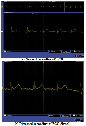 | Figure 3. Şekil 3. Keytek ECG Signal records |
Figure 3 demonstrates ECG signal records of newly designed ECG equipment by Keytek Limited under the supervision of Dr. Suleyman Bilgin[18]. Measurements were carried out in fully anechoic chamber at Akdeniz University, Industrial and Medical Based Microwave Research and Application Centre. Figure 3a shows normal recording of designed ECG equipment, and Figure3b shows GSM900 infected recordings at 1.5m distances. There are two important results concluded from this study. First conclusion is similar to other studies that mobile phone usage closer then approaching distance/critical distance can cause interference on ECG and EEG equipments. Nihon Kohden Cardiofax equipment is susceptible to GSM900 mobile phones at 1.25m distance as well as it are susceptible to 3G mobile services at 1m distance. Second and important conclusion comes from Table 4. As seen from the table that there are infected electronics in the case of lower uplink power levels. So, the critical distance is not a concern itself as mentioned in ANSI C63.18, but also the location and orientation of both sources and medical equipments are important. This is because of 3 dimensional resonant locations as a result of depolarized signals (there are electric field components of each coordinate obtained in the control room).
ACKNOWLEDGEMENTS
This study was supported by Akdeniz University Scientific Research Projects Supporting Unit (BAPYB) and State Planning Organization (Project number: DPT-2007K1205- 30). We also would like to thank to Dr. Suleyman Bilgin for his new design ECG.
References
| [1] | M. Brodlie, D. Robertson, and J. Wyllie, Interference of electrocardiographic recordings by a mobile telephone, Cardiol Young 2007; 17: 328–329, © Cambridge University Press, ISSN 1047-9511,doi: 10.1017/S1047951107000443. |
| [2] | A. Baranchuk, J. Kang, D. Campbell, S. Ribas, W.M. Hopman, H. Alanazi, D. P. Redfearn, and C.S. Simpson, Clinical Investigations Electromagnetic Interference of Communication Devices on ECG Machines, Clinical Cardiology, Volume 32, Issue 10, 588–592 (2009). |
| [3] | Sukru Ozen, Selcuk Helhel and O. Halil Colak Electromagnetic Field Measurements of Radio Transmitters In Urban Area And Exposure Analysis, Microwave and Optical Technology Letters, Vol.49, Issue 7, pp.1572-1578, July 2007. |
| [4] | Selcuk Helhel and Sükrü Özen, Assessment of Occupational Exposure to Magnetic Fields in The High Voltage Substations (154/34.5kV), Radiation Protection Dosimetry, Volume: 128 Issue: 4, Pages: 464-470, 2008. |
| [5] | W.E. Irnich, R. Tobisch, “Mobile Phones in Hospitals”, Biomed. Instrum. Technol. Vol:33, pp:28-34, 1999. |
| [6] | M.P.Robinson, I.D.Flintoft and A.C .Marvin, ’Interference to medical equipment from mobile phones, J.Med. Eng. Technol .,vol .21,pp.141-146,1997 |
| [7] | M. Hietanen,V.Sibakov, S.Hallfors and P.von Nandelstadh Safe use of mobile phones in hospitals ,J.Health Phys.Soc.,vol.79,pp.S77-S84,2000 |
| [8] | C. Kti-Tang, K. H. Chan, L. C. Fung, S. W. Leung, Electromagnetic Interference Immunity Testing of Medical Equipment to Second and Third Generation Mobile Phones, IEEE Trans. On Electromagnetic Compatibility, Vol: 51, No:3, pp:659-664, August 2009 |
| [9] | Electromagnetic compatibility of medical devices with mobile communications, in Medical Devices Bulletin DB9702.London,U.K.:Medical Devices Agency ,1999 |
| [10] | A.J. Trigano , A.Azoulay, M.Rochdi ,and A.Campillo , Electromagnetic interference of external pacemakers by walkie –talkies and digital cellular phones :experimental study , Pacing Clin.Electrophysiol ., vol .22,no 4,pp.588-593, APR.1999 |
| [11] | S. Helhel, Comparison of 900MHz and 1800MHz Indoor Propagation Deterioration, IEEE Transactions On Antennas and Propagation, Vol. 54, No. 12, pp. 3921-3924, December 2006, DOI Number: 10.1109/TAP.2006.884311. |
| [12] | Jochen Shniller, Mobile Communicaiton, 2nd edition, Addision Wasley, Essex, 2003. |
| [13] | American National Standard Recommended Practice for an On-Site, Ad Hoc Test Method for Estimating Radiated Electromagnetic Immunity of Medical Devices to Specific Radio-Frequency Transmitters, ANSI C63.18, 1997. |
| [14] | Helhel Selcuk; Ozen Sukru; Basyigit I. Bahadir, Kurnaz, Osman, Yoruk, Yunus E., Bitirgan, Murat, Colak, Zeynep, Radiated Susceptibility Of Medical Equipment In Health Care Units: 2g And 3g Mobile Phones As An Interferer, Microwave and Optical Technology Letters, Volume: 53 Issue: 11 Pages: 2657-2661 DOI:10.1002/mop.26321 Published: Nov 2011. |
| [15] | F.M. Tesche, M.V. Ianoz, and T. Karlsson, EMC Analysis Methods and Computational Models, A Wiley-Interscience Publications, Jhon Wiley&Sons, New York, 1997 |
| [16] | Nucci, C.A.; Rachidi, F. On the contribution of the electromagnetic field components in field-to-transmission line interaction. IEEE Trans. EMC 1995, 37, 505–508. |
| [17] | Paul, C.R. Analysis of Multiconductor Transmission Lines; Wiley Interscience: New York, 1994. |
| [18] | Keytek Elektrik – Elektronik Ltd. Şti,, Annual Report 2009, Antalya Technopolis, Antalya,TR. |
 Abstract
 Reference
 Full-Text PDF
 Full-Text HTML