American Journal of Biomedical Engineering

p-ISSN: 2163-1050    e-ISSN: 2163-1077

2011;  1(1): 44-54

doi: 10.5923/j.ajbe.20110101.08

A Bayesian Recursive Algorithm for Freespace Estimation Using a Stereoscopic Camera System in an Autonomous Wheelchair

Thanh H. Nguyen 1, Hung T. Nguyen 2

1Biomedical Engineering Department, International University, Quarter 6, Linh Trung, HoChiMinh city, VNU, Vietnam

2Faculty of Engineering and Information Technology, University of Technology, Sydney, Broadway, NSW, 2007, Australia

Correspondence to: Thanh H. Nguyen , Biomedical Engineering Department, International University, Quarter 6, Linh Trung, HoChiMinh city, VNU, Vietnam.

Email:

Copyright © 2012 Scientific & Academic Publishing. All Rights Reserved.

Abstract

This paper proposes a Bayesian Recursive (BR) algorithm for detecting freespace for people with severe disability operating an autonomous wheelchair with a stereoscopic camera system. Based on the left and right images captured from the camera system, the Sum of Absolute Differences (SAD) algorithm is used to produce a stereo disparity map. In short, a three-dimensional (3D) point map is converted to a two-dimensional (2D) distance map. This is generated from the disparity map using a geometric projection. Being based on uncertain information captured from the camera system, the BR algorithm for freespace estimation is developed as a recursive expression for the posterior probability function. The average probability values are calculated for the height and width of the freespace, and these assist to plan a power wheelchair pathway. Based on the average probability of the estimated height and width of the freespace, a Bayesian decision for the power wheelchair to autonomously navigate through the freespace is made. Moreover, Obstacle avoidance problem based on 2D map is considered in this paper. As further support for the method, experimental results indicate the effectiveness of the proposed algorithm.

Keywords: Autonomous Wheelchair, Bayesian Recursive Algorithm, Freespace Detection, Two-Dimensional Distance Map

Cite this paper: Thanh H. Nguyen , Hung T. Nguyen , "A Bayesian Recursive Algorithm for Freespace Estimation Using a Stereoscopic Camera System in an Autonomous Wheelchair", American Journal of Biomedical Engineering, Vol. 1 No. 1, 2011, pp. 44-54. doi: 10.5923/j.ajbe.20110101.08.

1. Introduction

Powered wheelchairs are necessary to assist the mobility of severely disabled people. However, in many cases, the use of a conventional wheelchair may be inadequate for this task. For this reason, additional equipment including specialized computer and control systems, are mounted on certain wheelchairs. In addition, novel algorithms are applied to enable them to be classified as smart wheelchairs[1-8]. The goal of the smart wheelchair is to enhance the independence of the user. In addition to equipping the smart wheelchair with sensors such as a camera, ultrasound and laser, many current technologies for autonomous wheelchairs based on techniques have been developed for mobile robots[9-13].
In recent years, single camera, ultrasound and laser sensors have been used to detect obstacles and freespaces in the environment surrounding mobile vehicles[14-19]. For example, a mobile robot may be equipped with ultrasonic sensors, helping to detect freespace and obstacle for its mobile operation[20-22]. In addition to freespace detection, a B-ayesian update theory is applied to compute the value, in a given direction, of “FreespaceProbability” at each point- mark[23]. A typical application is that a time correlation approach between the last and current image is taken in different time. This is achieved by using a single camera to detect the freespace in front of a vehicle driving on a highway[24-27]. However, using laser or ultrasound sensors would not only miss any information placed above or below the scanning plane, it would only provide 2D information of the plane. These are significant shortcomings indeed for the successful creation of mobile robots and wheelchairs. In order to improve obstacle and freespace detection, one can install a stereoscopic camera system on the motion wheelchair. This camera system can provide 3D information for wheelchair control calculation.
This project proposes an approach involving the detection of freespaces and obstacles using a stereoscopic camera system mounted on a power wheelchair. It is proposed that the camera system collects 3D information in an unknown environment. The power wheelchair autonomously detects both the height and width of freespaces and obstacles for collision avoidance. From the left and right images in particular captured by the camera system, the Sum of Absolute Differences (SAD) correlation method will be employed to determine stereo disparity. Given this disparity map, a 3D point map is generated using a geometric projection, in which the height and width of a freespace or an obstacle are determined. For the goal of detecting freespaces and obstacles, a 2D distance map is converted from this 3D map. Due to the camera system providing stereo 3D maps, this is a very feasible and effective approach. Essentially, the camera system shows enough information to carry out obstacle and freespace estimation, as well as collision avoidance. This is essential for the safe operation of the autonomous wheelchair. In order to illustrate the effectiveness of the approach, two 2D maps are compared using both laser and stereoscopic camera sensors. These will now be further described.
The SAD correlation method, using stereo cameras, has effectively detected landmarks and corresponding images, in which block matching methods are utilized. In recent years, these have served to estimate the disparity for pixels in a pair of stereo images[28-37]. In this paper, the SAD correlation algorithm takes one pixel in an image from a region of pixels. It then finds its closest match to a pixel in the corresponding region of the other image, and creates a disparity map[38,39]. Given this disparity map, a 3D point map and a 2D distance map are constructed. In this case, a SAD correlation algorithm using block matching has been chosen. This is due to its associated computational efficiency for determining disparity, and this plays an important role to autonomously navigate freespaces and obstacles[40].
Bayesian methods are often applied to mobile robots, in order to estimate locations and objects for the environment [41-45]. Using statistical tools, a Bayesian filter algorithm is employed to estimate locations based on sensor measurements. In order to compute the probability, the Bayesian filter algorithm uses the Markov assumption and recursive process[46]. In this project, a Bayesian Recursive (BR) algorithm is proposed to estimate the height and width of freespace, this being based on uncertain information from a stereoscopic camera system. This task is made more difficult due to the close proximity between the height and width of a freespace such as a doorway, and the height and diameter of the wheelchair. For this reason, the proposed BR algorithm will assist in estimating the height and width of the freespace to enable the decision of passing through the freespace.
Many researchers have been attracted to studying the obstacle avoidance or freespace passing approaches which are used in mobile vehicles. These vehicles are equipped with laser or ultrasound sensors in the indoor and outdoor environment. For example, a Vector Field Histogram algorithm was developed to detect unknown obstacles, and to avoid collisions in the scanning plane using 2D range data[47-49]. In addition to the freespace estimation algorithm, each sector in the Polar Histogram computes for avoidance by holding the polar obstacle density in that direction. In this paper, obstacle avoidance or anti-collision will be presented which is based on 3D information for the autonomous wheelchair. As such, the wheelchair will be designed to autonomously avoid obstacles in its direction and move through freespace.
In the wheelchair control system, user contribution is very important. Many researchers developed powered wheelchair for severely disabled people always focus on control parts that can encourage the healthy parts of user body such as cameras to detect eyes, gesture recognition and EMG (Electromyography), EEG (Electroencephalography) signals [50-54] for wheelchair control. For example, an intelligent wheelchair was installed a single camera and the EMG device to detect face movement. Thus, user can drive the wheelchair to go around in the indoor environment.
This paper is organized as follows. In Section 2, the determination of 2D map from stereoscopic vision is introduced. In Section 3, a BR algorithm based on conditional probabilities, control data and uncertain measured information is employed in an autonomous wheelchair to estimate the height and width of freespace. Section 4 discusses the anti-collision based on the density of distance values in 2D distance map. Section 5 shows the experimental results, whereby including the estimation of freespace using the BR algorithm, 2D map using a stereoscopic camera system, and the wheelchair control to pass through freespace. In Section 6, the discussion of the main results is represented. Section 7 concludes the paper.

2. Determination of 2D Distance Map from Stereoscopic Vision

2.1. Disparity Map

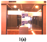
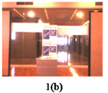
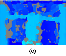
Figures 1a and 1b show the left and right images taken from a stereoscopic camera system. Based on these images, a disparity map will be estimated using the SAD correlation algorithm as shown in Figure. 1c. Using this estimation, the 3D point map is computed and converted to a 2D distance map from obstacles to the centre of the camera system. This may be determined for the objective of navigating obstacles and freespaces in a typical environment.
Figure 1a. Left image with the heights of two freespaces.
Figure 1b. Right image with the heights of two freespaces.
Figure 1c. Stereo disparity map, in which obstacles close to the camera position are represented as light blue.
In order to generate a disparity map, the correspondence is identified in different views of the scene and between image features. Subsequently, the relative displacement between feature coordinates in each image is calculated. As such, the correlation technique is applied to find the best match between the region of pixels in images.
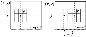
In particular, the main principle of the correlation techniques tests for the pixel located within a region. This is shown in image-2 of Figure 2, in which the best matches for a given pixel within a corresponding region are shown in image-1. As shown in Figure 2, assuming that d is the disparity and the correlation mask (region) is a square neighborhood around the pixel p(i,j).
Figure 2. Correlation of two 3x3 windows along corresponding epipolar lines to search for the best matching region.
In terms of both performance and efficiency for creating disparity between the left and right images, there are in practice several corresponding algorithms. These methods are Normalized Cross-Correlation (NCC), Sum of Squared Differences (SSD), Normalized SSD, Sum of Absolute Differences (SAD), Rank and Census[31]. All of these are applied to improve disparity mapping with better matching of two images. Based on the trade-off between performance and efficiency, and depending on the needs of the system, methods are implemented in typical applications. In the case of this real-time wheelchair control, the SAD algorithm is selected due to its associated computational efficiency.
The criterion for a best match in the SAD algorithm involves the minimization of the SAD of corresponding pixels in windows of the left and right images. In this paper, the SAD correlation algorithm is implemented to find the best match in the corresponding region between two images. In particular, for every pixel in a region shown in image-1 of Figure 2, a given square size neighborhood is selected from the reference image. This neighborhood is then compared to a number of neighborhoods in the other image (along the same row). Subsequently, the best match is selected, and the process repeated to find more matches. Based on these input, a disparity map is finally created[40].
Using the sum of absolution differences, the neighborhood comparison is achieved as follows:
(1a)
In which the SAD function is evaluated for all possible values of disparity d, the centre of a window of size (2M+1)x(2M+1) is located at the pixel coordinates (i, j).and (x, y) represents the coordinates in one image. Further examining the SAD function, IL and IR are the intensity functions of the left and right images.
In the SAD algorithm, the criterion for the best match is minimization of the SAD of corresponding pixels in two windows of the images. The disparity D of the windows in color images is expressed as follows:
(1b)
In which dmin, dmax represent minimum and maximum disparities. The disparity dmin of zero pixels corresponds to a very remote object, whereas dmax denotes the object’s closest position.
As shown in Figure 1c, the disparity map has been determined using the SAD correlation algorithm. Based on color images as shown in Figures 1a and 1b, the SAD algorithm is modified using the color intensities R B G to produce the stereo disparity map. According to typical color bands, its depths can are determined from obstacle to the camera position. For example, the point A compared to the point B in this map is closer to the camera position.

2.2. Computation of 2D Distance Map

A 2D distance map which provides for distance values from obstacles to the camera’s central position, is necessary for developing a control strategy for the wheelchair.
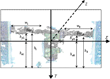
Figure 3a. Viewed from the front side; 3D point map computed to convert to 2D distance map, in which the first freespace has the height h1 and width w1, and the second freespace has the height h2 and width w2.
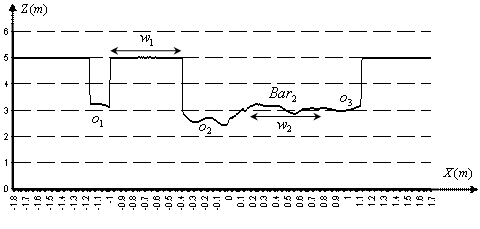
Figure 3b. 2D distance map only shows the first freespace with the width w1, so its height h1 is greater than the height of the wheelchair. The second is considered as an obstacle due to its having lower height than the wheelchair.
From the disparity map as shown in Figure 1c, a 3D point map is produced as shown in Figure 3a. The computation of 3D map has the following steps:
For each pixel p(x,y) in the left image and then find a corresponding pixel q(x’,y’) in the right image.
Calculate disparity d=x – x’
Determine the baseline B between two cameras and the focus length F from a stereoscopic camera system.
Calculate 3D position (X,Y,Z) of point p using the following equations.
(2)
Finally obtain a 3D point map as shown in Figure 3a.
This is then converted to a 2D distance map as shown in Figure 3b, and uses a geometric projection. The conversion of the 2D map includes the following five steps:
Step 1: Assume that there is a certain value Xi on the X-axis which corresponds to many points (Yj,Zk) in the 3D coordinate system (Xi,Yj,Zk), i, j, k=1,2,3…. A minimum distance value Zimin from an object to the camera position is chosen on the plane (Xi, Zk).
Step 2: A minimum distance value Zimin from an object to the camera centre corresponding to a point Yjmin is chosen for the vertical plane (Yj, Zk).
From Step 1 and Step 2, using the projection, a 2D distance map (Xi, Zimin) is generated from a 3D point map. The 2D distance map depends on the values Yjmin these being used to compute the height of a freespace.
Step 3: Consider freespaces in a 2D distance map. The height hl of the freespace is computed based on a 3D point map as follows:
(3)
In which hl ∈ Yjmin, l=1, 2, 3…, hc,l represents the height of the camera position mounted on a wheelchair to the ground. The height hy,l represents the camera position, and is the computed value from the top of the freespace to the centre of the coordinate system. For example, as shown in Figure 3a, there are two heights, h1 and h2 of two freespaces.
Step 4: The computation of the coordinate Z of the 2D distance map (Xi, Zimin) is as follows:
(4)
In which the selected value Zimin corresponds to the values Yjmin. This depends on the distance hl being computed and compared to the height of the wheelchair, alternately the height of the user sitting on the wheelchair. Finally, the 2D distance map (Xi, Zimin) are contingent on values Yjmin.
Step 5: The widths of the freespace wm, m=1, 2… are estimated based on maximum distances Zimax in the 2D distance map (Xi, Zimin). This is shown as follows:
(5)
In which the value Xi is summed up to create the width, and to correspond to the maximum values Zimax in the 2D distance map (Xi, Zimin). The values k1 and k2 are the first and last candidates of a freespace wm.
In practice, the left and right images have two freespaces, as shown in Figures 1a and 1b. But the height h2 of the second freespace is less than the height h1 of the wheelchair, which is considered to be an obstacle. As shown in Figure 3b, the 2D distance map is computed to show only one freespace w1, in which the height h1 of the first freespace is greater than the height of the wheelchair.
The main objective of computing the height and width of a freespace is to compare them to the height and diameter of the passing wheelchair. It means that if the height or width of the freespace is less than the height or diameter of the wheelchair, then it is unable to move through.

3. Freespace Estimation Algorithm

For facilitating the safe motion of mobile wheelchairs in an unknown environment, the problem of detecting freespace is an important part of the control strategy. In this project, the height and width of a freespace is computed, then compared to the height and diameter of the wheelchair. If the dimensions of a freespace are close to the dimensions of the wheelchair, it is difficult to estimate the dimensions of the freespace due to the uncertainty of information from the stereoscopic camera system. To solve this problem, a Bayesian Recursive (BR) algorithm is used in the mobile wheelchair for estimating freespace, and this is based on conditional probability, as well as measured information and control data. All these assist in computing the overall probability. The probabilistic average is then used to formulate the Bayesian decision for a motion.

3.1. Bayesian Recursive Algorithm

The BR algorithm includes two main steps to estimate the height and width of a freespace. The first step is the calculation of the probability based on the prior probability and the control u(t) over state (the height or width) x(t). The probability is expressed as follows:
(6)
In which P(x(t-1)), P(x(t)|u(t),x(t-1))) these being the previous probability, and the conditional probability, over state x(t-1).
The next step is that the probability Ppr(x(t)) is used along with the conditional probability based on measurements z(t) to make the following probability:
(7)
In which the Bayesian theorem is utilized for the posterior probability Ppo(x(t)) using ∑Ppo(x(t))=1.
Ppo(x(t)) represents the previous probability for the next time step, by using (6) to determine the posterior probability Ppr(x(t)). This also means the algorithm is performed recursively to compute the probability for the dynamic system.

3.2. Bayesian Decision

This BR algorithm is recursively iterated, with a view to producing the relevant probabilities. The average value of the probabilities is computed to make the following decision:
(8)
In which n represents a number of iterations.
Comparing the average probability Pav(x) to the average threshold probability Pth is undertaken, in which the threshold probability Pth is obtained from trial times. Providing that Pav(x) is greater than or equal to the value Pth, then the mobile wheelchair can decide to move through the freespace. If Pav(x) is less than Pth, then the wheelchair is not permitted to move through the freespace.
The BR algorithm is employed in the wheelchair to estimate the height and width of a freespace based on uncertain information measured from the camera system. This means that this BR algorithm is just used, when the height or width is close to the safe height or wheelchair diameter. This BR algorithm is recursively iterated using measured information, and control data for producing probabilities. The average of these probabilities is then computed to make the Bayesian decision. For making the final decision of the mobile wheelchair, the Bayesian decision is combined with alternate conditions of the control system.

4. Obstacle Avoidance

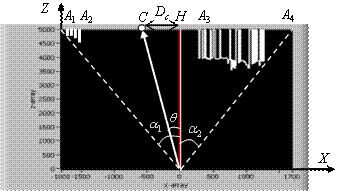
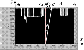
A stereoscopic camera system mounted on the wheelchair has a limited field of view, with an α1 maximum angle to the left of the wheelchair, and an α2 maximum angle to the right. Based on a 2D distance map with a Cartesian coordinate system and camera calibration, the freespaces and obstacles [40,55], as shown in Figure 4a, are detected for maintaining the wheelchair control.
In this project, a wheelchair control algorithm is developed based on the height and width of freespace in a binary histogram. This is computed for steering and speed controls using the camera system, and is different from algorithms of obstacle avoidance such as Vector Polar Histogram (VPH) [56] and Vector Field Histogram (VFH)[47]. For example, the VFH algorithm or the enhanced method VFH+[49] is based on the map grid C onto the primary polar histogram using laser or ultrasound sensor to represent obstacle avoidance algorithms. Based on active cells in the map grid, the angle and obstacle directions are computed for obstacle avoidance for mobile robots. For the wheelchair control to pass through the freespace using the stereoscopic camera system, the freespace centre is then determined based on the 2D distance map with the Cartesian coordinate system as shown in Figures 4a and 4b. Subsequently, this computes the steering angle for the wheelchair operation to pass through the freespace. Based on the estimated height and width of the freespace for the safety of the wheelchair, speed is also controlled. The Bayesian decision will determine for the mobile wheelchair to move through the freespace. In addition, the wheelchair was set up a ds=0.5 m safe distance for collision avoidance. It is assumed that when the wheelchair is too closed to obstacles (smaller than 0.5 m), the wheelchair will immediately avoid the obstacles for user safety. For this reason, the steering and speed controls will be calculated in the autonomous wheelchair.
Figure 4a. Left centre of the freespace A1A3; angles α1, α1 of the triangle A1OB. The steering angle θ from the centre of the freespace to H; A3A4 is the obstacle.
Figure 4b. Right centre of the freespace A2A3; θ is the steering angle, and A1A2 and A3A4 are the detected obstacles.
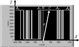
Figure 4c. Binary histogram determined from the 2D distance map.
In this paper, firstly the steering control function is dependent on the centre of freespace, and reflects the motion of the wheelchair to turn left or right. This is computed based on the 2D distance map obtained from the camera system. As shown in Figure 4c, a binary histogram corresponds to a binary threshold. This is created to determine the freespace and obstacle areas. Using this, the centre of the freespace is computed, and the steering angle for the wheelchair motion.
The speed of the wheelchair is computed based on the height and width of freespace in order to avoid collision. It is an advantage of the camera system that it can provide 3D measurements of the freespace in a specific environment. Therefore, the height and width of the freespace are computed in relation to the height and diameter of the wheelchair for collision avoidance. In this model, the height is computed from the 3D point map by using (2). The wheelchair is controlled to maintain the speed V during operations, and is dependent on the height and width of the freespace.

5. Experimental Results

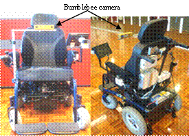
In this project, the power wheelchair has been fitted with a ‘Bumblebee’ stereoscopic camera system from Point Grey Research, and a ‘URG’ laser system. As shown in Figure 5, both of these apparatus are controlled by a computer at the University Research Centre for Health Technologies. The camera system contains two single cameras, both of which act as the two “eyes” for the left and right images.
Figure 5. Power wheelchair with the stereoscopic camera.
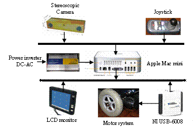
In addition, and as shown in Figure 6, the power wheelchair is equipped for other useful hardware devices. In particular, input data for the wheelchair is provided from the camera system. A list of extrinsic and intrinsic parameters of the camera system is shown, in which the baseline is 12cm in length, the focal length is 6mm with 500 HFVO, and the powered consumption is less than 2.5W. The URG laser and joystick are provided through an Apple Mac Mini computer, which in turn is powered through a DC-AC power inverter from the wheelchair battery. The input data is processed and displayed on an LCD monitor, producing driving signals to the wheelchair’s motor control system via NI USB-6008.
Figure 6. Hardware requirements for power wheelchair.
The wheelchair’s system requirements depend on the range of hardware devices used, as well as the software for processing the data and system control.

5.1. Experiment 1: 2D Map Using the Stereoscopic Camera

In this experiment, the power wheelchair for severely disabled people is fitted with a “Bumblebee” stereoscopic camera system. This apparatus assists in a real environment with freespace and obstacle detection. Experimental results performed using the same context, have demonstrated the effectiveness of using the camera system and the laser.
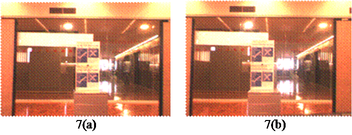
Figure 7a. Left image with an obstacle “Bar” of the first freespace. Figure 7b. Right image with an obstacle “Bar” of the first freespace.
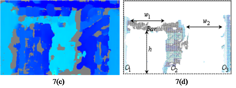
Figure 7c. Stereo disparity map with two freespaces. Figure 7d. 3D map with 2 freespaces w1, w2; 4 obstacles o1, o2, o3, “Bar”.
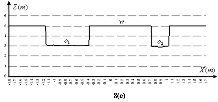
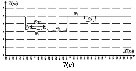
Figure 7e. 2D distance map using the camera system, in which the second freespace has the width w2. The width w1 of the first one is considered as an obstacle, this being due to the height being less than that of the wheelchair.
Figures 7a and 7b show the left and right images as captured from the stereoscopic camera system. The 3D point map is constructed from the stereo disparity map as shown in Figure 7c. This 3D point map, as shown in Figure 7d, has three obstacles, o1, o2, o3 and a bar. It also has two freespaces, w1 and w2, the first having a width of w1=1 m and a height of h1=1.15 m. The second freespace has a width of w2=1 m with no detectable obstacle height. The obstacles o1, o2 are detected from the camera position at 3 m and 4.5m respectively. The height h1 is computed by using (2), in which h1 is less than the wheelchair height of hw=1.2m. As shown in Figure 7e, this means the first freespace in the 2D distance map is considered to be the obstacle.
In the sense, the camera system mounted on the wheelchair represents 3D information at the maximum distance of 5m. It means that the wheelchair can recognize four obstacle, o1, o2, o3 and “bar”. Given the 3D information provided by the camera system, the wheelchair can detect the height h1 of the first freespace and pass through without collisions, if the height h1 is greater than that of the wheelchair. For this reason, the camera system compared to the 2D laser system is adequately used to provide stereo images with more sufficient information for increasing safety of the mobile wheelchair system for severely disabled people.

5.2. Experiment 2: Estimation of the Height and Width of Freespace Using the BR Algorithm

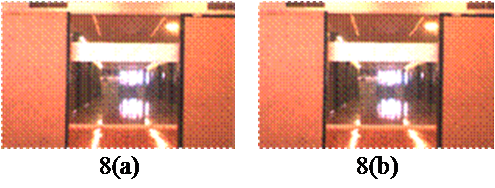
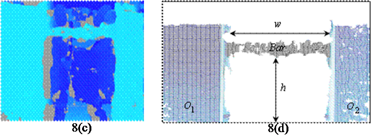
The BR algorithm is used in the wheelchair for estimating the height h and width w of a freespace. As shown Figures 8a and 8b, the left and right images are captured from the camera system. From these, the disparity and 3D point maps are constructed. These are shown in Figures 8c and 8d. Figure 8e shows a 2D distance map with a freespace w.
Figure 8a. Left image with a freespace, in which the height and width of the freespace is close to the height and diameter of the wheelchair. Figure 8b. Right image with one freespace, in which the height and width of the freespace is close to the height and diameter of the wheelchair.
Figure 8c. Stereo disparity map, in which obstacles close to the camera position are shown as light blue. Figure 8d. 3D map computed to convert to 2D distance map, in which the freespace has a height h, a width w, three obstacles o1, o2 and Bar.
Figure 8e. 2D distance map shows a freespace with a height h and a width w located close to the height and diameter of the wheelchair.
As shown in Figure 5, consider that the wheelchair has a height hw and a safe diameter ds and this is compared to a height h and width w of the freespace as shown in Figure 8d. Assuming that h > hw and w > ds, then there is a freespace in which the wheelchair can move. Assuming that h < hw or/and w < ds, then an obstacle is detected, and the wheelchair can not move through. If the height h or the width w is close to hw or ds, it is difficult to estimate the dimensions of the freespace. This is due to the camera showing indeterminate information.
For this reason, the BR algorithm is utilized in the wheelchair to estimate both the height and width of the freespace. If the height h or width w of the freespace is greater than, or equal to, the wheelchair height hw or diameter ds then, they are assigned as: “h=FS” or “w=FS”. If h or w is less than hw or ds, then they are assigned as: “h=OB” or “w=OB”. In this situation, if both the height and width of the estimated freespace are “h=FS” and “w=FS”, then there is a freespace. This primarily applies if the height and width of the estimated freespace is “h=OB” or “w=OB”, this denotes an obstacle. In this scenario, the wheelchair can’t move through the freespace.
In this experiment, it is assumed that the actual height of freespace ha is equal to the wheelchair’s safe height of hw=1.2m. However the measured height h of the freespace, as estimated by the camera system, is still uncertain. For this reason, the BR algorithm is used to estimate this height h.
Initially, the equal prior probabilities are given as follows:
(9a)
(9b)
Following this, the conditional probabilities corresponding to noise measurements and the height h(t) of the freespace at time t is carried out according to trial times:
(10a)
(10b)
(11a)
(11b)
In which if the height h(t) as measured by the camera system is greater than, or equal to, 1.2 m, z(t)=FS. They also hold if h(t) is less than 1.2 m, z(t)=OB.
The conditional probabilities dependent on the wheelchair control u(t)=move and prior states are shown as follows:
(12a)
(12b)
(13a)
(13b)
For similarity, the control case is ut=stop, and the conditional probabilities are computed as follows:
(14a)
(14b)
(15a)
(15b)
In which the error probabilities can occur relatively, as shown in (12b), (13b), (14a) and (15b).
Firstly, the wheelchair takes on control action u(t)=stop and the measurement z(1)=FS at time t1. The probability Ppr(h(1)) using the prior probability are computed by using (6):
(16a)
(16b)
Given the measurement z(1)=FS and Ppr(h(1)), the posterior probabilities Ppo(h(1)) are determined by using (7) as follows:
(17a)
(17b)
The BR algorithm is iterated for a consecutive time step, and corresponds to u(2)=move at time t2. We obtain the probabilities by using (6) as follows:
(18a)
(18b)
As the measurement is still z1=FS, we have the posterior probabilities by using (7) as follows:
(19a)
(19b)
This process is recursively iterated for some ten times, in order to produce the probabilities Ppo(h=FS), Ppo(h=OB). Finally, the average probabilities, Pav(h=FS), Pav(h=OB) are computed. For similarity, the BR algorithm is used to estimate the width w of the freespace, in order to show the average probabilities - Pav(w=FS), Pav(w=OB). The total and average probabilities are revealed in Table 1. In this case, the average probability Pav is chosen to make the Bayesian decision, providing it is greater than or equal to the threshold probability of Pth=0.8. Otherwise, if Pav is less than Pth, the freespace is considered as the obstacle and the wheelchair can not move through the freespace. Table 1 is shown the average probabilistic values.
In this case, if one of the two average probabilities Pav(h) or Pav(w) is less than the threshold probability Pth, then the wheelchair will not move through the freespace.

5.3. Experiment 3: Investigating the Capacity of the Wheelchair to Pass Through a Doorway

Controlling the wheelchair so it can move through a doorway is acknowledged as a difficult task. This is due to the dependence on the wheelchair’s steering, the speed controls and the estimate of the proximity to the doorway.
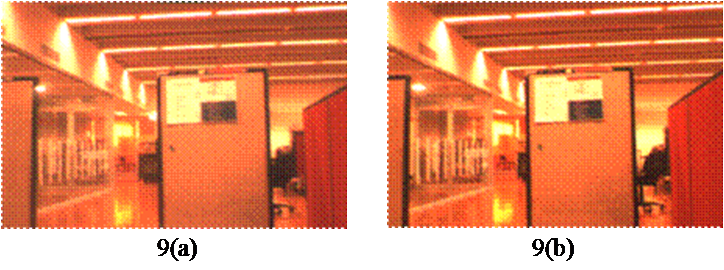
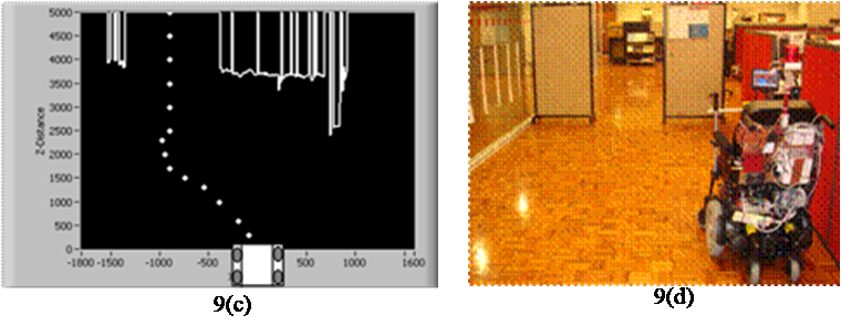
As shown in Figures 9a and 9b, the 2D distance map has resolved the coordinates to be processed from the left and right images. We can subsequently determine the 5m maximum Z-axis, and the 3.6m maximum X-axis, assuming the left side of the 2D distance map is -1.8m width and the right side is a width of 1.7 m. As shown in Figure 9c, the width and center of the doorway can then be computed. The overall scene of the doorway and the wheelchair are shown in Figure 9d. Moreover, the computed steering and speed controls are based on distance values between obstacles and the wheelchair position and the width of the doorway. In particular, the maximum travel speed of the wheelchair is 1m/s. The sample time for this real-time detection system is currently at 0.49sec. The change of the speed depends on the density of the distance values from obstacles to the wheelchair, while the steering angle is based on the width of the doorway.
Figure 9a. Left image showing the width w of the doorway. Figure 9b. Right image showing the width of the doorway.
Figure 9c. The moving direction for the wheelchair to pass through the freespace is the dotted line. Figure 9d. The overall experimental context for the wheelchair and the doorway.
In order for a wheelchair to move through a doorway, in the case, the width w of the doorway approximate the diameter ds of the wheelchair. However, this is very difficult to estimate due to uncertain information from the camera system, so a Bayesian Recursive (BR) algorithm is employed to estimate the width of the doorway. With the probabilities obtained from the BR algorithm, the average probabilities Pav of the doorway width are computed, and then compared to the threshold probability Pth. This serves to make the Bayesian decision for the motion of the wheelchair. If the average probability Pav is greater than or equal to the threshold probability Pth=0.8, then the Bayesian decision is chosen. This decision ensures that the wheelchair will pass through the doorway.
As shown in Figure 9c, the dotted line indicates the direction of the wheelchair moving through the doorway. Firstly, the wheelchair steers at an angle corresponding to the left side of the centre of the doorway, after that it turns a large right, and then proceeds straight to the doorway centre. The steering and speed of the wheelchair are computed in the wheelchair system. Figure 9d shows the total picture, including the start position for the wheelchair to move through, and the target doorway.

6. Discussion

A shared control wheelchair is to improve daily activities of severely disabled people[57,58]. The wheelchair is combined by an autonomous part and a contribution user part. In this paper, the autonomous wheelchair mounted with a stereoscopic camera system to detect freespace and obstacles for estimation and collision avoidance. In the autonomous wheelchair, a width safe distance, ds=0.5 m, from obstacle to the wheelchair and a height safe distance of the wheelchair, dh=1.2m, were set up for collision avoidance. It is assumed that the width distance from the wheelchair to the obstacle is smaller than 0.5m and the height distance of the gateway is smaller than 1.2m, the wheelchair will autonomously move to avoid collision.
In order to calculate 2D map, firstly a SAD algorithm was employed to determine a stereo disparity map. The next step is that, 3D cloud map was obtained using a geometric projection given the stereo disparity map. Finally, the 2D map was converted from the 3D map. In this case of using the SAD algorithm, this is an unexpensive calculation and it also obtains enough information of 2D map and 3D map for design of the autonomous wheelchair control.
In the autonomous system, 2D map-based wheelchair control was focused on calculating steering and speed for obstacle avoidance. In addition, a BR algorithm was applied to estimate the width and height of freespace, such as an indoor gateway, before the wheelchair decides to move through this freespace to avoid collision to two sides of the gateway for the user safety. This algorithm simply detects to make the decision for the wheelchair to pass through.
A brief discussion of using the stereoscopic camera system is that a laser system, such as the ‘URG’ laser system[10,11,47,48], can only detect freespaces and obstacles at a maximum distance of 4 m and provide 2D map. For this reason, the wheelchair using the ‘URG’ laser system only provide 2D information above the ground without any information above or below in the scanning plane. Therefore, the wheelchair can not recognize the height of the freespace, such as a door with “bar height” or tables with their heights. So the wheelchair with the laser system can collide to the bar object of a gateway during its motion. Wheelchairs using laser or ultrasound systems could not avoid “bar” obstacles (gateway height), so 2D maps using these sensors do not have enough information.

7. Conclusions

This paper has presented the computation for the SAD algorithm for disparity map, as well as 3D point map to generate 2D distance map with freespaces and obstacles. The BR algorithm for freespace estimation has also been outlined. Given the left and right images captured from the camera system, the SAD algorithm is employed in the mobile wheelchair to generate a 3D point map. This is then computed to convert to a 2D distance map using a geometric projection. In order to estimate freespace, a BR algorithm based on the conditional probability, uncertain information and control data is utilized. To make the Bayesian decision, it is necessary to compute the average values of probabilities. Finally, the Bayesian decision is enabled for facilitating the wheelchair motion by severely disabled people to move through the freespace. In addition to the freespace estimation, the calculation of collision avoidance for the autonomous wheelchair was carried out based on 2D map. It means that the wheelchair can autonomously avoid obstacles too closed to it or stop to turn right or left. Overall, experimental outcomes undertaken in a real environment, have demonstrated the effectiveness of the algorithm

ACKNOWLEDGEMENTS

This research is partly supported by an ARC Discovery Grant (DP0666942). The researchers would also like to acknowledge the contribution Prof. Vo van Toi for his advice about the structure of this paper.

References

[1]  Y. Adachi, K. Goto, Y. Matsnmoto, and T. Ogasawara, "Development of Control Assistant System for Robotic Wheelchair - Estimation of User's Behavior based on Mea- surements of Gaze and Environment," in Proceedings of the IEEE International Symposium on Computational Intelli- gence in Robotics and Automation, 2003, pp. 538-543
[2]  L. M. Bergasa, M. Mazo, A. Gardel, R. Barea, and L. Boquete, "Commands generation by face movements applied to the guidance of a wheelchair for handicapped people," in Proceedings of the 15th International Conference on Pattern Recognition, 2000, pp. 660 - 663
[3]  Y. Kuno, T. Yoshimura, M. Mitani, and A. Nakamura, "Robotic wheelchair looking at all people with multiple sensors," in Proceedings of IEEE Inter. Conf. on Multisensor Fusion and Integration for Intell. Sys., 2003, pp. 341 - 346
[4]  I. Moon, K. Kim, J. Ryu, and M. Mun, "Face Direction-Based Human-Computer Interface using Image Observation and EMG Signal for The Disabled," in Proceedings of the IEEE Imter. Conf. on Robotic and Auto., 2003, pp. 1515-1520
[5]  T. N. Nguyen, S. W. Su, and H. T. Nguyen, "Robust Neuro-Sliding Mode Multivariable Control Strategy for Powered Wheelchairs," IEEE Transactions on Neural Syst- ems And Rehabilitation Eng., vol. 19, pp. 105-111, 2011
[6]  H. Seki, K. Ishihara, and S. Tadakuma, "Novel Regenerative Braking Control of Electric Power-Assisted Wheelchair for Safety Downhill Road Driving," IEEE Transactions on Industrial Electronics, vol. 56, pp. 1393-1400, 2009
[7]  Y. Oonishi, S. Oh, and Y. Hori, "A New Control Method for Power-Assisted Wheelchair Based on the Surface Myoelect- ric Signal," IEEE Transactions on Industrial Electronics, vol. 57, pp. 3192-3196, 2010
[8]  F. Chénier, P. Bigras, and R. Aissaoui, "An Orientation Estimator for the Wheelchair’s Caster Wheels," IEEE Trans. on Control Systems Tech., vol. 19, pp. 1317-1326, 2011
[9]  R. C. Simpson, "Smart Wheelchairs: A Literature Review," Journal of Reh. Research & Dev., vol. 42, pp. 423–436, 2005
[10]  R. C. Simpson, D. Poirot, and F. Baxter, "The Hephaestus Smart Wheelchair system," IEEE Trans. on Neural Systems and Rehabilitation Engineering, vol. 10, pp. 118 - 122, 2002
[11]  S. P. Levine, D. A. Bell, L. A. Jaros, R. C. Simpson, Y. Koren, and J. Borenstein, "The NavChair Assistive Wheelchair Navi- gation System," IEEE Transactions on Rehabilitation Engin- eering, vol. 7, pp. 443 - 451, 1999
[12]  R. Simpson, E. LoPresti, S. Hayashi, I. Nourbakhsh, and D. Miller, "The Smart Wheelchair Component System," Journal of Reh. Research & Dev.t, vol. 41, pp. 429–442, 2004
[13]  Q. Zeng, B. Rebsamen, E. Burdet, and C. L. Teo, "A Collaborative Wheelchair System," IEEE Trans. on Neural Systems and Rehabilitation Eng., vol. 16, pp. 161 - 170, 2008
[14]  D. An and H. Wang, "VPH: A New Laser Radar Based Obstacles Avoidance Method for Intelligent Mobile Robots," in Proceedinfs of the 5th Congress on Intelligent Control and Automation, 2004, pp. 4681-4685
[15]  J. Borenstein and Y. Koren, "The Vector Field Histogram-Fast Obstacle Avoidance for Mobile Robots," IEEE Tran. on Robotics and Auto., vol. 7, pp. 278-288, 1991
[16]  I. Ulrich and J. Borenstein, "VFH+: Reliable Obstacle Avoidance for Fast Mobile Robots," in Proceedings of the IEEE Inter. Conf. on Robots and Auto., 1998, pp. 1572-1577
[17]  Z. Xiang, Z. Xu, and J. Liu, "Small obstacle detection for autonomous land vehicle under semi-structural environme- nts," in Proceedings of IEEE Intelligent Transpor- tation Systems, 2003, pp. 293 - 298
[18]  S. P. Parikh, V. G. Jr., V. Kumar, and J. O. Jr., "Usability Study of a Control Framework for an Intelligent Wheelchair," in Proceedings of the IEEE International Conference on Robotics and Automation, 2005, pp. 4745-4750
[19]  Y. Murakami, Y. Kuno, N. Shimada, and Y. Shirai, "Intelligent Wheelchair Moving among People Based on Their Observations," in Systems, Man, and Cybernetics, The IEEE International Conference on Systems, Man, and Cybernetics. vol. 2, 2000, pp. 1466-1471
[20]  J. Borenstein and Y. Koren, "Error Eliminating Rapid Ultrasonic Firing for Mobile Robot Obstacle Avoidance," IEEE Trans. on Robotics and Aut., vol. 11, pp. 132-138, 1995
[21]  S. Shoval, J. Borenstein, and Y. Koren, "The Navbelt—A Computerized Travel Aid for the Blind Based on Mobile Robotics Technology," IEEE Transactions on Biomedical Engineering, vol. 45, pp. 1376-1386, 1998
[22]  I. Ulrich and J. Borenstein, "The GuideCane—Applying Mobile Robot Technologies to Assist the Visually Impaired," IEEE Transactions on Systems, Man, and Cybernetics-Part A: System and Humans, vol. 31, pp. 131-136, 2001
[23]  Y. L. Ip, A. B. Rad, and Y. K. Wong, "Autonomous Exploration and Mapping in an Unknown Environment," in Proceedings of The International Conference on Machine Learning and Cybernetics, 2004, pp. 4194 - 4199
[24]  P. Cerri and P. Grisleri, "Free Space Detection on Highways using Time Correlation between Stabilized Sub-pixel precision IPM Images," in Proceedings of the IEEE Inter. Conf. on Robotics and Automation, 2005, pp. 2223-2228
[25]  H. Sermeno-Villalta and J. Spletzer, "Vision-based Control of a Smart Wheelchair for the Automated Transport and Retrieval System (ATRS)," in Proceedings of the IEEE Inter. Conf. on Robotics and Automation, 2006, pp. 3423 - 3428
[26]  C. J. Taylor and D. J. Kriegman, "Vsion-Based Motion Planning and Exploration Algorithm for Mobile Robots," IEEE Trans. on Robots and Auto., vol. 14, pp. 417-426, 1998
[27]  P. E. Trahanias, M. I. A. Lourakis, A. A. Argyros, and S. C. Orphanoudakis, "Vision-Based Assistive Navigation for Robotic Wheelchair Platformsy," in Machine Vision Applica- tions Workshop, Graz, Austria, 1996
[28]  Y. W. Huang, S. Y. Chien, B. Y. Hsieh, and L. G. Chen, "Global Elimination Algorithm and Architecture Design for Fast Block Matching Motion Estimation," IEEE Trans. on Circuits and Sys. For Video Tech., vol. 14, pp. 898-907, 2004
[29]  J. Vanne, E. Aho, T. D. Hämäläinen, and K. Kuusilinna, "A High-Performance Sum of Absolute Difference Implemen- tation for Motion Estimation," IEEE Trans. on Circuits and Sys. for Video Tec., vol. 16, pp. 876-883, 2006
[30]  K. Lengwehasatit and A. Ortega, "Probabilistic Partial- Distance Fast Matching Algorithms for Motion Estimation," IEEE Transactions on Circuits for Video Technology, vol. 11, pp. 139-152, 2001
[31]  M. Z. Brown, D. Burschka, and G. D. Hager, "Advances in computational stereo," IEEE Transactions on Pattern Analysis and Machine Intel., vol. 25, pp. 993 - 1008, 2003
[32]  H. F. Ates and Y. Altunbasak, "SAD Reuse in Hierarchical Motion Estimation For The H.264 Encoder," in Proceedings of the IEEE inter. on Acoustic, Speech, and Signal proc. 2005
[33]  D. L. Fowler, T. Hu, T. Nadkarni, P. K. Allen, and N. J. Hogle, "Initial trial of a stereoscopic, insertable, remotely controlled camera for minimal access surgery," Surg Endosc, vol. 24, pp. 9–15, 2010
[34]  S. Rodríguez, J. F. D. Paz, P. Sánchez, and J. M. Corchado, "Context-Aware Agents for People Detection and Stereo- scopic Analysis," Trends in PAAMS, AISC vol. 71, pp. 173–181, 2010
[35]  S. Rodríguez, F. d. l. Prieta, D. I. Tapia, and J. M. Corchado, "Agents and Computer Vision for Processing Stereoscopic Images," HAIS pp. 93–100, 2010
[36]  R. A. Hamzah, R. A. Rahim, and Z. M. Noh, "Sum of Absolute Differences Algorithm in Stereo Correspondence Problem for Stereo Matching in Computer Vision Application " in The 2010 IEEE Conference, 2010, pp. 652-656
[37]  M. Brezan, "HYBRID METHOD OF 3-D IMAGE RECONSTRUCTION FROM STEREO PICTURES," in The 2008 IEEE 3DTV-Conference, 2008, pp. 189-192
[38]  S. Gutiérrez and J. L. Marroquín, "Robust approach for disparity estimation in stereo vision," Image and Vision Computing, vol. 22, pp. 183-195, 2004
[39]  E. Izquierdo, "Disparity/segmentation analysis: matching with an adaptive window and depth-driven segmentation," IEEE Transactions on Circuits and Systems for Video Technology, vol. 9, pp. 589 - 607, 1999
[40]  T. H. Nguyen, J. S. Nguyen, D. M. Pham, and H. T. Nguyen, "Real-Time Obstacle Detection for an Autonomous Wheelchair Using Stereoscopic Cameras," in The 29th Annual Inter. Conf. of the EMBC, 2007, pp. 4775 - 4778
[41]  S. Thrun, W. Burgard, and D. Fox, Probabilistic Robotics: Cambridge, Mass. : MIT Press, 2005
[42]  Y. L. IP, A. B. Rad, and Y. K. Wong, "Autonomous Exploration and Mapping in An Unkown Environment," in Proceedings of the IEEE Third International Conference on Machine Learning and Cybernetics, 2004, pp. 4194-4199
[43]  R. K. Srivastava and K. Deb, "Bayesian Reliability Analysis under Incomplete Information Using Evolutionary Algori- thms," pp. 435–444, 2010
[44]  S. Salti and LuigiDiStefano, "On-Line Learning of the Transition Model for Recursive Bayesian Estimation," in the 2009 IEEE 12th International Conference on Computer Vision Workshops, 2009, pp. 428-435
[45]  R. Singh, E. Manitsas, B. C. Pal, and G. Strbac, "A Recursive Bayesian Approach for Identification of Network Configu- ration Changes in Distribution System State Estimation," IEEE Transactions on Power Systems, vol. 25, pp. 1329-336, 2010
[46]  V. Fox, J. Hightower, L. Liao, D. Schulz, and G. Borriello, "Bayesian Filtering for Location Estimation," IEEE Pervasive Computing, vol. 2, pp. 24-28, 2003
[47]  J. Borenstein and Y. Koren, "The Vector Field Histogram - Fast Obstacle Avoidance For Mobile Robots," IEEE Journal of Robotics and Automation, vol. 7, pp. 278-288, 1991
[48]  J. Borenstein and Y. Koren, "Error Eliminating Rapid Ultrasonic Firing for Mobile Robot Obstacle Avoidance," IEEE Tran. on Robotics and Auto., vol. 1, pp. 132-138, 1995
[49]  I. Ulrich and J. Borenstein, "VFH+: Reliable Obstacle Avoidance for Fast Mobile Robots," in Proceedings of the 1998 IEEE Intcrnational Conference on Robotics & Auto- mation, 1998, pp. 1572-1577
[50]  S.-Y. Cho, A. P. VINOD, and K. W. E. CHENG, "Towards a Brain-Computer Interface Based Control for Next Generation Electric Wheelchairs " in The 2009 3rd International Conf. on Power Electronics Systems and Applications 2009
[51]  Y. Zhang, J. Zhang, and Y. Luo, "A Novel Intelligent Wheelchair Control System Based On Hand Gesture Recognition " in Proceedings of the 2011 IEEEIICME Inter. Conf. on Complex Medical Engineering 2011, pp. 334-339
[52]  C. S. L. Tsui, P. Jia, J. Q. Gan, H. Hu, and K. Yuan, "EMG-based Hands-Free Wheelchair Control with EOG Attention Shift Detection " in Proceedings of the 2007 IEEE Inter., Conf. on Rob. and Biomimetics, 2007, pp. 1266-1271
[53]  L. Wei, H. Hu, T. Lu, and K. Yuan, "Evaluating the Performance of a Face Movement based Wheelchair Control Interface in an Indoor Environment " in Proceedings of the 2010 IEEE International Conference on Robotics and Biomimetics, 2010, pp. 387-392
[54]  J. Heitmann, C. Köhn, and D. Stefanov, "Robotic Wheelchair Control Interface based on Headrest Pressure Measurement " in 2011 IEEE Inter. Conf. on Rehabilitation Robotics 2011
[55]  T. H. Nguyen and K. T. Vo, "Freespace Estimation in an Autonomous Wheelchair Using a Stereoscopic Camera System " in The 32nd Annual International Conference of the IEEE EMBS, 2010, pp. 458-461
[56]  D. An and H. Wang, "VPH: A New Laser Radar Based Obstacle Avoidance Method for Intelligent Mobile Robots," in Proceedings of the 5th World Congress on Intelligent Control and Automation, 2004, pp. 4681-4685
[57]  C. Urdiales, B. Fernandez-Espejo, R. Annicchiaricco, F. Sandoval, and C. Caltagirone, "Biometrically Modulated Collaborative Control for an Assistive Wheelchair," IEEE Transactions on Neural Systems And Rehabilitation Engineering, vol. 18, pp. 398-408, 2010
[58]  H. T. Trieu, H. T. Nguyen, and K. Willey, "Shared Control Strategies for Obstacle Avoidance Tasks in an Intelligent Wheelchair," in The 30th Annual International IEEE EMBS Conference, 2008, pp. 4254-4257