-
Paper Information
- Next Paper
- Previous Paper
- Paper Submission
-
Journal Information
- About This Journal
- Editorial Board
- Current Issue
- Archive
- Author Guidelines
- Contact Us
American Journal of Biomedical Engineering
p-ISSN: 2163-1050 e-ISSN: 2163-1077
2011; 1(1): 41-43
doi: 10.5923/j.ajbe.20110101.07
Design of a Microcontroller Based and X-Ray Waveform Independent kVp-Meter
 Abstract
 Reference
 Full-Text PDF
 Full-Text HTML
Y. Ülgen , M. Tümer
Boğaziçi University, Institute of Biomedical Engineering, 34682, Çengelköy-Istanbul, Turkey
Correspondence to: Y. Ülgen , Boğaziçi University, Institute of Biomedical Engineering, 34682, Çengelköy-Istanbul, Turkey.
| Email: |  |
Copyright © 2012 Scientific & Academic Publishing. All Rights Reserved.
The kVp setting is one of the major factors affecting the image quality in X-ray imaging and should be annually measured and calibrated if necessary. In this work, a kVp-meter is designed around the ATmega16 (Atmel) microcontroller, based on the physical principle that the linear attenuation coefficient of materials, namely copper has a smooth dependence on the energy level of the X-ray photons. Based on the logarithm of the ratio of the radiation intensities through 0.5mm and 1mm thick copper filters, a look-up table is generated in the range 60-120kVp. Logarithmic operation increased the precision at higher kVp values. Since sampling is performed over the exposure period in a continuous manner, the measurement is not affected by the X-ray waveform. A prototype unit was built and the performance was tested in terms of accuracy, precision and reliability.
Keywords: kVp Meter, Linear Attenuation Coefficient, X-ray Imaging
Cite this paper: Y. Ülgen , M. Tümer , "Design of a Microcontroller Based and X-Ray Waveform Independent kVp-Meter", American Journal of Biomedical Engineering, Vol. 1 No. 1, 2011, pp. 41-43. doi: 10.5923/j.ajbe.20110101.07.
1. Introduction
- The kVp control of the X-ray device is a measure for the energy level of the emitted X-rays and corresponds to the penetrating power of the beam. To increase the contrast on the radiographic image, the kVp should be adjusted according to the type of the tissue. The kVp affects not only the intensity reaching the image receptor but also the subject contrast of the image. An uncalibrated X-ray machine leads to unnecessary exposure of the patients. For this reason, the kVp adjusting circuit of the X-ray machines should be controlled on regular basis. There are various ways to measure the kVp like direct measuring method (with high-voltage divider), X-ray spectroscopy or the Wisconsin kVp test cassettes.Electronic kVp-meters provide a measurement based on the change in X-ray transmission through varying thicknesses of filtration. kVp-meters in general do not measure the true peak voltage; but rather an effective kV value by integrating the detector's outputs over exposure time and then taking their ratio. The instrument then corrects this value, usually according to a switch set by the user to indicate what type of X-ray machine (1Φ or 3Φ or DC) is being measured, to give an effective kVp by knowing the amount of ripple in the waveform. The method employed in this article relays on the same principle, namely the dependence of the linear attenuation coefficient µ of copper on the energy level of the X-ray photons: if µ can be measured, then the energy level of the photons, hence the kVp can be determined. Copper material is used since its µ exhibits a smooth behaviour within the energy range of X-ray imaging[1,2] as can be seen from Figure 1.
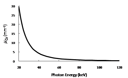 | Figure 1. The relation between the linear attenuation coefficient of copper and the incident photon energy. |
2. Method and Measurement
- A. Calculation of µThe relationship between the intensities of an X-ray beam, before and after passing through a material of thickness t is formulated by the Beer- Lambert Law, where µ is the effective linear attenuation coefficient of the material and corresponds to the mean energy level of the photons[3,4]:
 Copper is used as filtering material. The thickness and radiation intensity are known. But the intial intensity of the beam I0 is also not known like µCu. Since there are two unknowns, two equations are needed to solve and. two copper slabs of thicknesses of 0.5mm and 1mm respectively were irradiated from an X-ray source (Siemens Multix Compact K with Half Value Layer = 3mm Al). Then the intensities of the beams are given as
 and
and  By taking the ratio of X-ray dose measurements I1 and I2 for the two slabs of thicknesses t1 and t2, the common term I0 was eliminated and the equation readily solved for µCu:
 | (1) |
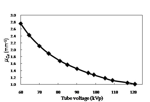 | Figure 2. The relation between linear attenuation coefficient and kVp. |
 | Figure 3. Block diagram of the kVp meter. |
 | Figure 4. Placement of the photodetectors inside a lead case to allow only beams from the X-ray source to reach the photodiodes. |
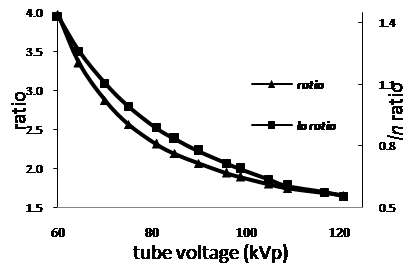 | Figure 5. Ratios of intensities and logarithm of ratios vs. kVp. |
3. Results and Discussion
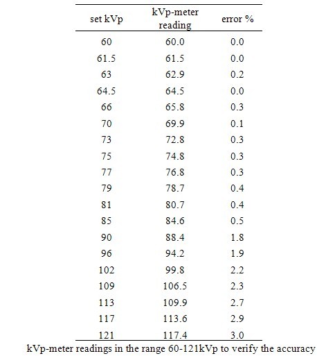
- A. AccuracyFollowing further correction of the look-up table, the device performed with a better accuracy. Siemens Multix Compact K was used to evaluate the accuracy of the kVp meter. Results are given in Table 1. The accuracy of the prototype unit was less than or equal 0.4% for kVp values between 60 and 81; and for kVp measurements above 90 kVp the error reached 3% at 121kVp as shown in Table 1.B. PrecisionThe kVp on the X-ray unit was set to 81kVp for assessing the precision with repeated measurements. The mean value and the coefficient of variation, defined as the ratio of the standard deviation to the mean value, were calculated as 80.72kVp and 0.08% respectively, which is below the 1% limit.C. Dependence on mAsTo test the dependency of the measurements on the exposure level, several measurements were conducted at constant kVp, but varying mAs (5 to 60mAs). There were no deviations in the readings. It is concluded that the device measurements are independent of mAs settings on the X-ray unit over a wide range of mAs.
|