Nickolay Zosimovych
School of Robotics, Xi’an Jiaotong-Liverpool University, 111 Ren'ai Road, Dushu Lake Higher Education Town, Suzhou Industrial Park, Suzhou, Jiangsu Province, China
Correspondence to: Nickolay Zosimovych, School of Robotics, Xi’an Jiaotong-Liverpool University, 111 Ren'ai Road, Dushu Lake Higher Education Town, Suzhou Industrial Park, Suzhou, Jiangsu Province, China.
| Email: |  |
Copyright © 2021 The Author(s). Published by Scientific & Academic Publishing.
This work is licensed under the Creative Commons Attribution International License (CC BY).
http://creativecommons.org/licenses/by/4.0/

Abstract
This paper proposes a communication system for nanosatellite Earth observation preliminary design technique as useful tools for managing and improving various aspects of regional and national resources. Has been estimated and proposed a design process for the low Earth orbit nanosatellite communication system. In proposed paper on basis of structural optimization technique have been formulated and solved next goals: reviewed Earth observation systems and studied their design parameters, analyzed the on-board antennas design background and provided analytical estimations, such as design a passband quadrature phase shift keying transmitter and receiver in Simulink, was obtained a bit error rate curves by using a Simulink / MathWorks, generated an offset quadrature phase shift keying waveform and investigated their characteristics, observed and analyzed the diagrams, constellation, and the signal trajectories of quadrature phase shift keying according contemporary design concept. All this allows to propose innovative communication system design techniques applied for the nanosatellite category.
Keywords:
Nanosatellite, Signal, Communication, Satellite, Antenna, Modulation
Cite this paper: Nickolay Zosimovych, Communication System for Nanosatellite Earth Observation, International Journal of Aerospace Sciences, Vol. 9 No. 1, 2021, pp. 1-12. doi: 10.5923/j.aerospace.20210901.01.
1. Introduction
One of the common intentions is to bring many countries the opportunity to operate nanosatellite for Earth observation (EO) missions and utilize the data effectively at low costs, as well as to develop and build application-driven missions [1].And one of the possible methods for this is to take full benefit of the ongoing know-how developments leading to additional miniaturization of engineering components, growth of micro-technologies for sensors and tools which allow to design dedicated, well-focused Earth observation missions. The trends of technology progress in the space piece important for disaster control are described by that nanosatellite can deliver data more rapidly with a better contest to user needs.Know-how progresses in the ground segment address networking, allowing it to get a successful response time and providing user-oriented space-segment control.The tendencies in the program segment of cost effective EO missions for disaster caution and support are focused on new applications and new data products [1]. There are some new advances that may show to significantly improve the abilities of nanosatellite EO missions [1,2]:1. The merging of data acquisition and data visualization knowledge.2. The complete disposal of new small launchers and the increase of space tourism.3. The progress of smaller, lighter, lower power satellites that can act as a constellation or independently.Nowadays primary satellite launch sites include: 1) Kourou, French Guiana; 2) Cape Canaveral, Florida; 3) Vandenberg Air Force Base, California; 4) Baikonur, Kazakhstan; 5) Jaquan Satellite Launch Center, China; 6) Taiyuan Satellite Launch Center, China; 7) Wenchang Satellite Launch Center, China; 8) Xichang Satellite Launch Center, China.In this case we should admit that the most dramatic change has been the entry of the Russian, Ukrainian, Chinese and Malaysian launch systems worked as joint ventures with US or European companies. That new launch systems around the world are even starting to use key components made in other countries, extra blurring national divisions. The cumulative accessibility of these low-cost launchers and the advance of distributors has released promises for single launches of a constellation as well as individual payloads [3,4].In this regard a great role is played by the communication system. The communication system is a particular on-board electronic complex of tools, together with the ground segment, which solves the following tasks: downlink (to on-board receiving) and decoding on-board control commands and numerical data, collecting, storing, pre-processing and uplink (transmitting information to receptions), as well as trajectory measurements. The antenna devices for uplink and downlink of high frequency radio signals are separate systems. This system includes antennas, coaxial cables and waveguides, switching and locking devices [5].Usually, the nanosatellite mission payload involves the communications equipment with the antennas and repeater comprising the transponders. The rest of the satellite is called the satellite bus. The bus transports the communications payload around in its orbit, offers electrical power, maintains attitude, points the payload, keeps the satellite on station, and makes orbit variations. The thermal control subsystem keeps the electronics and other components inside a safe temperature range over the life of the nanosatellite. The nanosatellite structure grips all together and defends the components throughout launch and after deployment on orbit. An on-board beacon transmits signals to aground tracking, telemetry, and command (TT&C) station (Fig. 1) [10]. The on-board telemetry system reports the health and status of all on-board systems and receives commands to control all on-board systems in support of the payload mission to provide continual communication services for all users. An Omni antenna offers communications connectivity during all phases of the mission [6].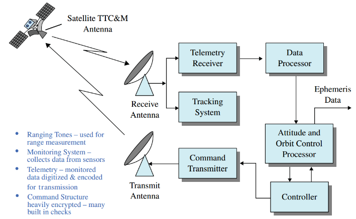 | Figure 1. Nanosatellite tracking, telemetry, command, and monitoring (TTC&M) [10] |
In these circumstances antenna systems have greatly enlarged in complexity. Space segment antennas are: 1) deliver high gain capabilities to comfort user requirements; 2) can spatially separate different portions of the field of view, permitting the existing bands to be used; and 3) can ease interference. Of all the know-hows used in the space segment, antenna systems are the most varied as an outcome of different operating frequencies and system requirements [7]. So, the goals of this research are next: 1. Review nanosatellite Earth observation systems and study their main characteristics.2. Estimate the on-board antennas design background and provide some analytical investigations.3. Design a passband quadrature phase shift keying transmitter and receiver in Simulink. 4. Obtain bit error rate curves by using a Simulink design in conjunction with an m-file.5. Generate an offset quadrature phase shift keying waveform and investigate its characteristics. Observe the diagrams, constellation, and the signal trajectories of quadrature phase shift keying.
2. Nanosatellite Earth Observation System
Nowadays, civil EO programs have become valued tackles for decision makers at many points [1]. Samples of such decision makers comprise resource managers, urban and regional planners, agricultural producers and disaster first responders. EO data can be particularly valuable for small countries and regions in supporting their upcoming growth. During the Summer Session Program in 2006 we all worked on a project SOL (Syst`eme d’Observation Locale or Local Observation System) [8]. The sample was settled using three test cases that have shown an interest in evolving an EO program: Catalonia, Spain; Alsace, France; and the Island of Mauritius. A planned charge chain for EO organisations, on basis of structural optimization technique, straight from the EO earner and to the end users as achievement that information is shown in Fig. 2. The main ideas useful to the value chain are the EO projects analysed, cost estimating methods and financing options [1].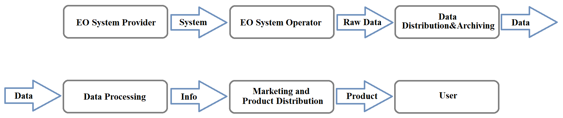 | Figure 2. EO value chain [1] |
Once a small country or region develops its own EO programs, the national and international policies and legal framework for space should also be considered, in performance with the scientific development route and package funding. By means of a cooperative model, small countries and regions can overcome difficulties and grow EO programs that meet the detailed requirements for any of the regions. The SOL project covers all that features of EO to find out the top decisions for small countries or regions. The example of Catalonia, an independent community of Spain, one of the most suited examples among the test cases studied, to prove the importance of SmallSat technology in small countries and regions [1]. EO can be valuable in Catalonia for viticulture, mapping, environmental monitoring, disaster management, and humanitarian aid. It is known that Catalonia is now using EO data for some applications, but the region could additionally capitalize on EO technology and build capacity in EO system development. The analysis of the density and vigoro of the vine canopy is an essential tool to assess the harvest and the wine class. To attain such a mark, a minimum spatial resolution of at least 2.0 m is required, irrespective of the time-based and radiometric determination constraints. Regarding environmental applications, there are a variety of EO applications that could be attempted by means of different solutions (space-, airborne- or ground based), and inside the set of budget constraints. Another option would be to make use of airborne systems, grouping with on-site ground observations. A possible space-based solution could be grounded on the use of a micro-satellite, with medium-to-high resolution sensors. As an example of that application would be the use of an appropriate platform to be united in the DMC-2 constellation, with a CHRIS sensor achieving spatial resolutions of about 17 m [1,2].That novel expansion is very inspiring for the SmallSat- nanosatellite business in Spain, and is linked to the next important application in Catalonia as disaster management. Come back to times below one or two days would be anticipated for a proper management of river flooding, as well as for the proof of identity of the present state of infrastructures under the properties of any natural disaster of short life period. That is why any new satellite should be integrated into an already existing constellation, such as DMC.The recognised gap between the data of EO providers and decision makers about EO systems, and the assumption that each region or country has specific needs, directed the group to grow a sample software named SOL Selection Tool (SOLST) [1].Proposed in Ref. [1] tool such as SOLST can support users to mark the suitable decisions of datasets for an exact application. The system architecture of that tool is collected from databases, an electronic interface, and linkages between the databases and interface. The databases involve detailed information about EO applications, data types and readiness, estimated system and data costs. The outputs aid as options for the EO system and/or data that are optional for the region and the application being examined.As already mentioned before, cooperation is frequently the most reliable and accurate method for small countries and regions to gain access to EO data, and this seems to be positive to nanosatellite as well. Ref. [1] mentioned that Surrey Satellite Technology Limited is a nice case of a cooperative venture that led to the design, manufacturing, testing, and launching of several identical nanosatellites. Another tool will help address the limits of such satellites by highlighting possible trade-offs. For small countries or regions, budget, technical capability and human resources are critical factors.In Ref. [9] estimated that partnerships are being designed to manufacture, assemble and deploy nanosatellites in space. Some space manufacturing companies, like Made in Space, and low earth orbit services provider, NanoRacks, are cooperating for CubeSat creators. That service is being called Stash & Deploy. It will supply a variation of standard and customer-specific components on-board a satellite deployment platform, like the International Space Station. These components will be used for rapid manufacturing of nanosatellites.Research shows that the nano- and microsatellite marketplaces will grow from $702.4 million in 2019 to $1887.1 million in 2024. Moreover, start-ups like Spire and Black Sky Global have collected tens of millions in venture cash from the likes of Bessemer Venture Partners, Lemnos Labs, RRE Ventures, and Vulcan Capital. Another start-up, Skybox Imaging, raised about $91 million in venture capital for EO satellites. The company was developed by tech giant Google for $500 million in 2019. After the gaining, Google has now retitled the company to Terra Bella to drive home the point that the company will not only put small imaging satellites into orbit, it would also analyze succeeding images for EO [9]. Ref. [9] show that learning by Northern Sky Research has opened that EO is the primary driver in arrears this industry’s growing. This is since the EO market hurts from data poverty in many fields, like agriculture, disaster management, forestry and wildlife. “Right now, the resolution of our satellites is 1 meter. Our business is to enable people to look at the global economy, and 1 meter is the critical resolution required to do that. We have no intention of going for big satellites with 30-cm resolution. We believe it’s all about revisit rates and persistence; so, we will stay optimized around that solution space,” says Planet Labs President Robbie Schingler.
3. The Design Background
From Ref. [7] we can estimate that commercial EO systems are configured to serve particular market segments and are planned to provide as much system capacity from the offered frequency distribution as possible. These concerns result in system designs that have relatively fixed coverage supplies and techniques to expand system capacity by reusing the same frequency spectra. As marked R. Dybdal in Ref. [7], design is an iterative process, and the quantity of iteration will rise as system complication and the number of users remains to growth. The system design process shown in Fig. 3 specifies the iterative nature that must be addressed by system designers. At a highest level, system-level aims outline the user data transfer and treatment requirements, the incidence allocations to be used, and preliminary assessments of G/T and ERP (effective radiated power) constraints for both the space and user segments. These requirements are used to develop system design concepts based on preliminary assessments of performance capabilities for the space and user segments. A most important and fundamental part of system definition is questioning and understanding the impacts of system requirements.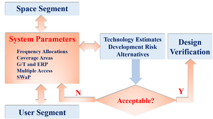 | Figure 3. The system design process [7] |
The system design concepts are likened with launch vehicle constraints for the space segment and compared with production costs for the user segment [7].In these circumstances, antenna technology to provision system description and development plays a main role in planning practical system designs. This antenna technology base has importantly contributed to existing system aptitudes.At the low earth orbit (LEO), the earth-satellite links are much shorter, leading to minor pathlosses, which results in lower power, smaller antenna systems. In this case propagation delay is also less because of shorter path distances. But, at the same time, a major disadvantage of the LEO nanosatellite is its restricted operations period, since the satellite is not at a fixed location in the sky, but instead bends across the sky for as little as 8 to 10 minutes from a fixed location on earth. If continuous global or wide area coverage is desired, a constellation of multiple LEO satellites is required, with links between the satellites to allow for point-to-point communications [10].Fig. 4 shows the on-board processing transponder, also called a regenerative repeater, or “smart satellite.” The uplink signal at f_up is demodulated to baseband, f_baseband. As mentioned in Ref. [10], the baseband signal is available for processing on-board, including reformatting and error-correction. The base band information is then re-modulated to the downlink carrier at f_(down,) possibly in a different modulation format than the uplink, and, after final amplification, transmitted to the ground. The demodulation/remodulation process removes uplink noise and interference from the downlink, while allowing additional on-board processing to be accomplished. Thus, the uplinks and downlinks are independent with respect to evaluation of overall link performance, unlike the frequency translation transponder where uplink degradations are co-dependent, as argued before.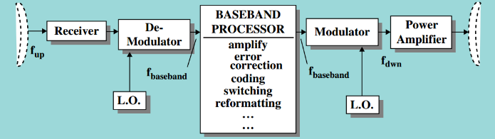 | Figure 4. On-board processing transponder [10] |
On-board processing nanosatellite tend to be more complex and expensive than frequency translation ones. However, they offer significant performance advantages, particularly for small terminal users or for large diverse networks.The most frequently used antennas on LEO spacecraft are [11]: 1) N-Turn Helix; 2) 1/2 wave Quadrifilar Helix; 3) full wave Quadrifilar Helix; 4) patch; 5) horn (at microwaves); 6) dish (mostly at microwaves).Helix antennas are very common for many different spacecraft’s uses, and they can achieve gains up to about 15 dB. The antenna can also be pressed flat (like a bed spring) so that in the packed configuration it occupies small space. When on orbit, the turns of the antenna are released to let the helix deploy to its design length. Flexible lines tied between consecutive turns guarantee that the deployed antenna has its design length. For example, that antenna gain for the 2.5 turn helix was about 5.5 dB.before….The half wave quadrifilar antenna has a 1 GHz bandwidth and a peak antenna gain of about 4 dB. Usually, it provides Earth Coverage from LEO. A full wave quadrifilar has improved gain, but it is used mainly because its antenna pattern peaks at 60° (30° down from the spacecraft horizontal). This is the angle of the horizon from about 600 km. Moreover, the antenna gain is compact at nadir, better matching the slant range path loss [11]. The link margin versus elevation angle is shown in Fig. 5.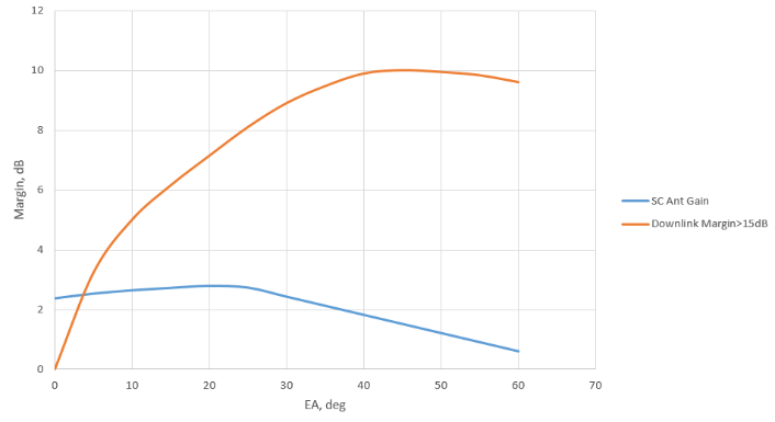 | Figure 5. Improving the low lavation link margin through use of full wave quadrifilar antenna (Downlink from 200 km LEO, 10 km SC FSK Xmitter at 2.25 GHz, 2.4 m ground antenna (32 dB gain), 3 dB NF 3.9 GHz and antenna Beam width) |
The turnstile antenna is well-suited to provide circularly polarized Earth coverage for satellites below about 800 km. That antenna is small (at S-band, about 2" × 2") and firm [11]. It easily resists launch vehicle loads (Fig. 6).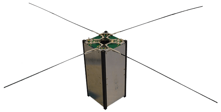 | Figure 6. Turnstile antenna in CubeSat [12] |
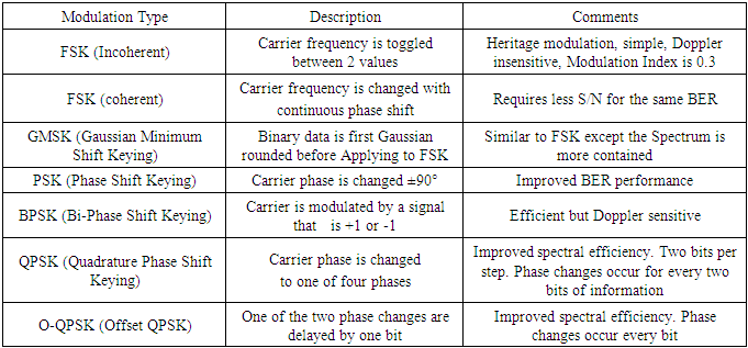
Nanosatellites are only permitted to transmit and receive in allocated bands. From Ref. [11]: the VHF frequencies are suitable for low data rate applications. The nanosatellites antennas, because of their size, are usually omnidirectional and are usually not steerable. Antennas must often be packed, because of their deployed size, and released when on orbit. Since radio frequency interference on the ground raises the ground station RF noise above the KTB noise level by more than 10 dB, effective communication needs either sufficient nanosatellite transmitter power or high gain ground station antennas.The UHF frequencies are similarly used for low data rate applications. However, the nanosatellite antennas are lesser. Terrestrial noise, while greater than KTB, is less than at VHF, and ground stations with larger antenna gains are smaller in size. All of these factors permit working at higher data amounts (usually hundred Kbps). Communications from and to a nanosatellite use digital data and one of some modulation types. The most often used modulation types and their general characteristics are given in Table 1 [11].Table 1. Some modulation types and their characteristics used in nanosatellites [11]
 |
| |
|
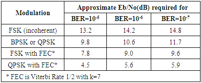
Beforehand the communication links can be designed and the required conventional S/N can be determined, possessions of the different modulation methods must be evaluated. There is a great quantity of different error improvement codes with diverse assets. From Ref. [11] it is seen that presenting FEC has an important influence on reducing the Eb/No required for a given BER. This is seen from the summary given in Table 2, showing the Eb/No required for BERs ranging from 10−5 to 10−7. Table 2. Summary of Eb/No requirements for different modulations and BER
 |
| |
|
The comparatively small length of a pass of a LEO SmallSat nanosatellite over a ground station, and the low maximum antenna gains for Earth coverage harshly limit the amount of data that can be downlinked from a satellite during a pass. Fig. 7 proves the length of a pass from a 600 km orbit altitude satellite to a ground station at various CPA spaces from the ground trace of the nanosatellite.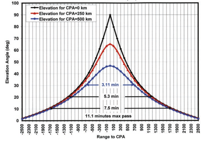 | Figure 7. Elevation angle vs. ground range and pass durations in communicating to a ground station at a given CPA from the satellite ground trace [11] |
The spacecraft ground trace CPA to the ground station rises, pass lengths get smaller, and the maximum elevation angles become minor. At a 250 km CPA and an elevation angle above 20°, for example, the pass is only about 3 min long. With an Earth coverage spacecraft antenna and a large (2.4 meter) ground station dish antenna operating at 1 Mbps data rate, the maximum volume of data that can be downlinked in a pass is about 300 Mbits or 37.5 Mbytes [11].Additionally, a steerable satellite’s antenna that tracks the ground station can provide a sufficient large antenna gain to raise the quantity of data that can be downlinked to 10 times more than an Earth coverage spacecraft antenna [10]. Additional approaches of growing a nanosatellites capability to downlink great amounts of data are next to use: 1) multiple ground stations; 2) ground stations at high latitude, where the number of orbits visible per day is larger (at least for highly inclined orbits); and 3) a geostationary relay satellite.A typical LEO NanoSat and SmallSat RF subsystem is shown in Fig. 8 [11]. This design assumed that packetization, randomization to balance the data stream for 0 DC component, forward error correction and encryption are done both in digital hardware or software in the C&DH computer. The data stream complete for transmission enters the S-Band 10-watt transmitter where it is QPSK modulated. That data may be telemetry (TTM) or payload data. The design services a nadir looking main antenna and an anti-nadir looking secondary antenna to assure that TTM could be sent to the ground even if the nanosatellite hurt an attitude control anomaly, or if the satellite has just been unconfined from the launch vehicle and is reducing. Due to the data amount of TTM is very minor compared to the data rate of the main mission payload, a power splitter is used to dump most of the power into the main antenna, and only a small amount of power is fed to the anti-nadir patch antenna. In this example, 1 Mbps data is fed to the main antenna and the TTM is only 9.6 kbps. Therefore, when the nanosatellite is inverted, TTM transmissions reach the ground with the same power density as the main data when the satellite is nadir pointing [11].
4. Results and Discussion
Let us start on the main definitions for the radio bridge a board-Earth needed to clarify the requirements for on-board antennas. Suppose that in some rectangular coordinate system, rigidly connected with the satellite, the direction from nanosatellite to the TT&C station is characterized by angles  and
and  . Moreover, these angles are chosen so that they may determine an arbitrary position TT&C station relative to the specified system. Then the power of the radiation generated by the radiating antenna, you can write the following expression:
 | (1) |
where  continuous function of angles
  and
and  a coefficient that is independent of input angles.Function
  characterizes the antenna pattern. The directivity or directive gain of the
  antenna in a given direction, characterized by
  angles, is the ratio of the power radiated by the antenna in this direction to the average power in all directions. According to the definition and formula
 where we integrate over the entire sphere of unit radius centred at the origin. If
  for all
  angles, then this is a non-directional antenna.The antenna efficiency
  is called the ratio
 where
where  the total power radiated in all directions;
  power supplied to the antenna.Antenna gain in the direction
  is the ratio of the power supplied to the non-directional antenna, a power input to a given antenna. This is true provided that the field strength in the location of reception is the same for both antennas, and the efficiency of a hypothetical non-directional antenna is one.It is evident that the gain depends on the specific values of the angles
  and the gain characteristic of the power supplied to the antenna. In contrast, the gain values
  take into account the efficiency of the antenna. These values are related by the following expression
 On-board satellites antenna from the point of view of the requirements that they impose systems of the apparatus can be divided into three classes: 1) omnidirectional; 2) unidirectional; and 3) highly directional. Omnidirectional antennas are in the directional diagram of which there is no sufficiently pronounced maximum, and also there are no long dips in angle and depth. The directional coefficient of such antennas is in the range from 0.01 to 0.1. Since the exact calculation of the radiation pattern of such antennas is a rather time-consuming process, the installation location and its design are finally checked on a special SmallSat antenna layout.Unidirectional antennas have a radiation pattern enclosed only in part of the space. As a rule, their diagrams are less indented. Unidirectional antennas require nanosatellite to be oriented in space with at least one axis, since outside the working angles the directional coefficient is close to zero (Fig. 8).
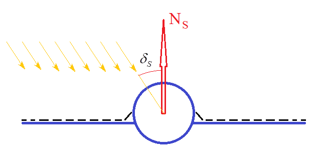 | Figure 8. Scheme fixed stationary planar antenna structurally combined with solar panels |
Such antennas are used on the orbital compartments of interplanetary automatic vehicles with a flat stationary solar battery, the normal of which  (Fig. 9) throughout the mission, is continuously oriented to the sun with some maximum error
  This is typical because during the reception of signals, both the working angles of the antennas and the distance from the ground to the satellite change.
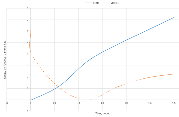 | Figure 9. Dependence of range  and angle and angle  of the Sun-nanosatellite-Earth on mission time of the Sun-nanosatellite-Earth on mission time |
Suppose that the position of the other axes of the nanosatellite is arbitrary, i.e. possible rotation around the normal  In this case, it is natural to require that the antenna radiation pattern be close to the body of revolution with an axis of symmetry parallel to the normal
  The intersection of the radiation pattern by a plane passing through the axis of symmetry is characterized by the dependence
  where
where  is the angle between the axis of symmetry and the direction to the receiving point.
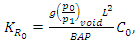 | (2) |
where  data transmission rate, which is desirable to have throughout a mission, or at selected sites missions;
  safety factor.If
  to plot in Cartesian coordinates, and to apply these graph diagrams of various antenna directivity, it is possible to examine the suitability of a particular embodiment. Sometimes it may be that given information rate
  cannot be implemented in some parts of a mission, i.e.
  . Since the information transmission speed proportional gain
  the implemented data transmission rate is defined as:
  | (3) |
Highly directional antenna - it is an antenna with a distinct half-power chart peak of not more than a few degrees. These antennas require an orientation axis by an electrical antenna receiving point. The directional coefficient of such antennas is from several tens to tens of thousands. There is a highly directional antenna radiation pattern, always oriented with respect to the structural base of the antenna, and a multi-element antenna is electrically controlled. At last, the maximum of the radiation pattern can be oriented on the reception point without changing the SmallSat orientation and without turning the antenna relative to the housing.
5. Characteristics of Quadrature Phase Shift Keying Signals
As a main technique to get better antenna and communication characteristics is a structural and parametric optimization. A passband quadrature phase shift keying (QPSK) signal non–pulse-shaped can be expressed as [12]: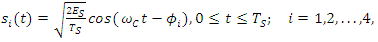 | (4) |
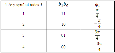
 The
The  is determined according to two data bits
  and
and  which form one quaternary symbol, as shown in Table 3 [13].
Table 3. Phase-Bit Mapping for 4-Ary Symbols [20]
 |
| |
|
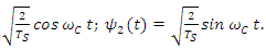
Let the two-orthonormal basis functions be 
 So, the QPSK signal
  can be written in terms of the basic functions in next form:
 | (5) |
Next, let us convert  into a point in the two-dimensional (2-D) vector space spanned by the orthonormal basis functions
  and
and  . And, from the results possibly determine the
  coordinates of
  in the vector space.Usually, a M phase shift keying signal is stated as
 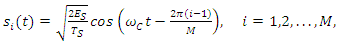 where
where  denotes the energy per
  any symbol.After last expression, and substitution the values of
  in Table 3 we can express
  in equation (5) as
 | (6) |
where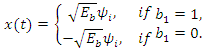 | (7) |
According to equation (7),  and
and  can be viewed as follows:
  is an antipodal binary phase shift keying signal, which transmits the bit
  using the basis function
  the dimension along the x axis;
 is an antipodal binary phase shift keying signal, which transmits the bit
  using the basis function
  the dimension along the y axis.Therefore, the QPSK signals
  can be viewed as the sum of two independent binary phase shift keying signals, one carrying
  and one carrying
  The main parameters of the modulator are set as follows:QPSK symbol duration
  sec; carrier frequency
  30 Hz;bit energy
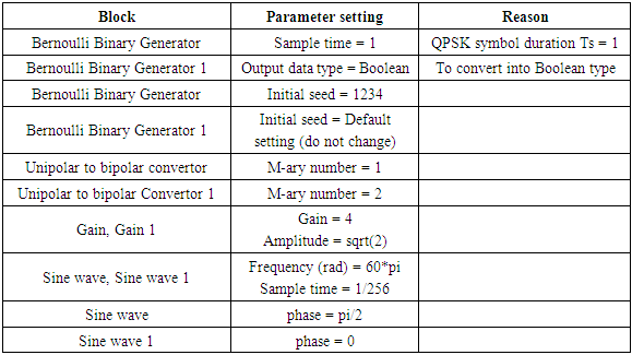
  = 16;the number of samples per symbol in the passband QPSK waveform are equal to 256.Based on equations (6) and (7), we can design an mdl/slx-file for the QPSK transmitter (Fig. 10). After identified that blocks whose outputs corresponds to
 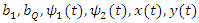 and
and  in equations (6) and (7) respectively, the setting parameters represented in Table 4.
Table 4. Setting Parameter for the QPSK Transmitter Design [20]
 |
| |
|
 | Figure 10. QPSK transmitter simulation |
During the next step, was created  that consists of 20 QPSK symbols. In this section was designed the QPSK receiver that estimates
  and
and  from
from  . Because of the orthogonality between the I and Q channels, the QPSK receiver is structurally effectively two BPSK receivers running in parallel [13].Fig. 11 illustrates the correlation step between
  and
and  used to extract parametric improvements the in-phase component.
 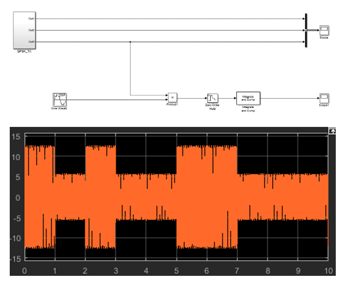 | Figure 11. Correlation step to extract the in-phase component |
6. Design a QPSK Receiver
For next operations was used a technique proposed in Ref. [13]. Complete an mdl/slx file to extract the quadrature component. Then possible to complete the whole receiver that will parametric demodulate both the in-phase and quadrature components. For this case, we can create the two basic functions  and
and  The Simulink subsystem QPSK_TX that created in 2D has two sinusoidal blocks Sine Wave and Sine Wave1 that generates the two basic functions. Since the receiver needs the same pair of basic functions, you can copy these two blocks for the receiver or create them the new blocks but set their parameters the same as these two blocks.Next, use the two Product blocks and the two Integrate and dump blocks, one for the in-phase component and one for the quadrature component, are identical. The integration interval should be equal to the bit duration. Set the internal parameter Integration period (Number of samples) of the two Integrate and dump blocks to 256. The simulation time is 20 seconds.The result in 3D should show that relative to the transmitted waveform, the detected but stream is delayed by one-bit duration.Like the eye diagram, the constellation diagram [13], which provides a visual insight on the performance, is also an important diagram for digital communication systems. In order to observe the constellation diagram of the received QPSK symbols, you need to modify the mdl/slx file as shown in Fig. 12. The major changes are that we have added the Real-Image to the complex block and the Constellation Diagram block to the outputs of the Integrate and dump block for both the I and Q channels. The parameter Symbols to display is equal to 1000. In the mdl/slx design window, was established the Simulation stop time to 2000.
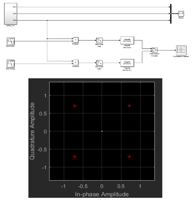 | Figure 12. QPSK receiver design with a constellation diagram scope |
7. Constellation Diagram and Phase Error
In this step, let us open the subsystem QPSK TX and insert a Gaussian Noise Generator block, connected as shown in Fig. 13, and set its parameter Sample time to 1/256.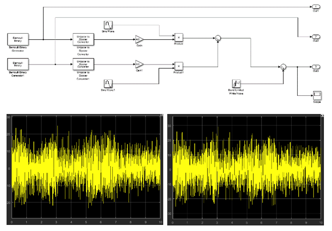 | Figure 13. Modeling of the received QPSK signal over an AWGN channel ( and =30 dB) and =30 dB) |
The following procedure allow verifying and structurally and parametric optimizing the setting parameter Variance of the Gaussian Noise Generator block, assuming  dB in proposed experiment:• Convert
  [dB] into the linear scale value. • Find
  from
from  and the current
  set in the mdl/slx file. • Substitute
  into the noise variance setting expression, that is, the variance of noise sample =
  . The parameter
  denotes the sample interval of the sampled waveforms. Thus, it is set to be equal to 1/256, as was mentioned earlier.After that capture the display window of Constellation Diagram and prior to capture, select the automatic axis scaling option in the display window menu. In this subsection, we observed the constellation diagram when there is a phase error. For this purpose, set the parameter Variance of the Band-Limited White Noise block to 0 to simulate the noiseless case. Then, open the parameter setting windows of Sine Wave and SineWave1and add pi/4 to the current setting of their parameter Phase (rad). After that let us run the simulation and capture the display window of Constellation Diagram (Fig. 14).At the end was repeated for phase errors of 150, 300, and 600, and justified the results generated in the simulation (Fig. 14).
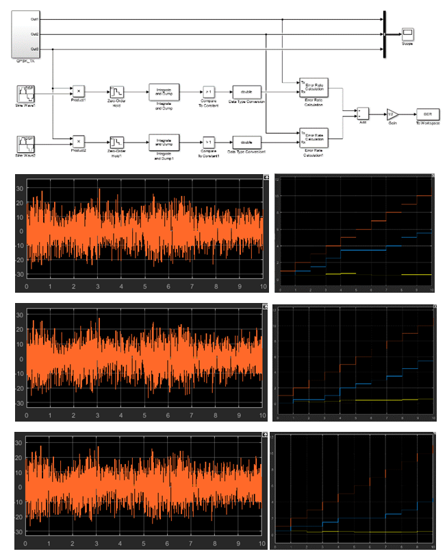 | Figure 14. Completed mdl/slx file for QPSK BER simulation |
8. Pulse Shaping and Instantaneous Signal Amplitude Study
In this step it should be noted that the baseband signal multiplied by the output of Sine Wave becomes the parametric passband signal whose spectrum is centred at the carrier frequency of 30 Hz. Thus, the outputs of Gain and Gain 1 structurally correspond to the baseband signals of the I channel and Q channel, respectively. Here we investigate the pulse shape of the baseband signals in the current design. It connected the outputs of Gain and Gain 1 to the Scope and ran the simulation for 10 seconds. Then captured the display window of Scope.The rectangular pulse in the time domain corresponds to a sinc function in the frequency domain. Thus, pulse-shaping using a rectangular pulse is bandwidth inefficient. Let us perform the raised cosine pulse shaping.To this end, was inserted a Raised cosine Transmit Filter block between the Gain and Product blocks and another one between the Gain1 and Product1 blocks. Later was set the MathWorks simulation parameters as follows (Fig. 15):• Roll-off factor: 0.75;• Output samples per symbol: 256;• Input processing: Element as channels (sample-based).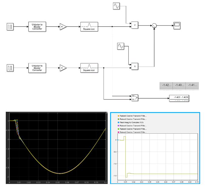 | Figure 15. Pulse-shaped QPSK system with signal trajectory |
9. Conclusions
This paper proposes a communication system for nanosatellite Earth observation preliminary design technique. Earth Observation data are useful tools for managing and improving various aspects of regional and national resources. As nanosatellites are amongst the cheapest systems to develop and launch, this will often be the preferred option of small countries and regions, and the selection tool is thus likely to bring benefits to the small satellite industry. In these circumstances may find EO as a powerful tool that has great potential for assisting with environmental management and other important applications for small countries and regions. System design processes have been estimated for low Earth orbit nanosatellite and most frequently used space segment antennas were studied. This allowed me to get next research goals: 1. Was reviewed nanosatellite Earth observation systems and studied their main characteristics.2. Estimated the on-board antennas design background and provided some analytical investigations. 3. Designed a passband quadrature phase shift keying transmitter and receiver in Simulink. 4. Are obtained bit error rate curves by using a Simulink design in conjunction with an m-file. 5. Generated an offset quadrature phase shift keying waveform and investigated its characteristics. 6. Are observed the diagrams, constellation, and the signal trajectories of quadrature phase shift keying. During analysis of the nanosatellite Earth observation system value chain, on-board processing transponder functions have been estimated and proposed. As a result of structural and parametric optimization, the system design process for unidirectional antennas was built. MathWorks modelling allows finding characteristics of quadrature phase shift keying signals. Pulse shaping and instantaneous signal amplitude have been modelling and innovative design parameters were found.
References
| [1] | Sandau R, Röser HP, Valenzuela A (Eds.), Small Satellites for Earth Observation: Selected Contributions, Springer, 399, 2008. [Online]. https://www.springer.com/gp/book/9781402069420. |
| [2] | Zosimovych N, 1U CubeSat Platform Design. Int. Journ. of Aerosp. Sc., No 8 (1), 2020: 1-7. [Online]. http://article.sapub.org/10.5923.j.aerospace.20200801.01.html. |
| [3] | Zosimovych N, Commercial Launch Vehicle Design, LAP LAMBERT Academic Publishing, 184, 2016. [Online]. https://www.researchgate.net/publication/313903416_Commercial_Launch_Vehicle_Design. |
| [4] | Zosimovych N, Sounding Rockets Scattering Factors and their Influence on Motion Accuracy. 4th Int. Conf. on Aeronautical Materials and Aerosp. Eng. (AMAE 2020), 14-17 May 2020, Chengdu, China, Vol. 887, IOP Conf. Series: Materials Sc. and Eng. [Online]. https://iopscience.iop.org/article/10.1088/1757-899X/887/1/012018. |
| [5] | Zosimovych N, Chen Z, 3D Printing CubeSat: A Low-cost Mode of Space Exploration. Aeronautics and Aerosp. Open Access Journ., Vol. 2 Issue 5, 2018: 320-324, MedCrave Publisher. [Online]. https://pdfs.semanticscholar.org/c3a9/4e563c230cc4799a40094253b253ac067088.pdf. |
| [6] | Welti CR, Satellite Basics for Everyone, iUniverse, 142, 212. [Online]. https://www.twirpx.com/file/1309076/. |
| [7] | Dybdal R, Communication Satellite Antennas: System Architecture, Technology, and Evaluation. The McGraw-Hill Companies, 344, 2009. [Online]. https://www.twirpx.com/file/1364459/. |
| [8] | The International Space University, SOL, Strasbourg, 2006. [Online]. http://www.esa.int/esapub/bulletin/bulletin126/bul126e_elaerts.pdf. |
| [9] | The future of earth observation is in small satellites, 2016. [Online]. https://www.geospatialworld.net/article/earth-observation-small-satellites-industry/. |
| [10] | Ippolito LJr, Satellite Communications Systems Engineering. John Wiley & Sons Ltd, 2nd ed., 458, 2017. [Online]. http://33h.co/2zhrx. |
| [11] | Sebestyen G, Fujikawa S, Galassi N, Chuchra A, Low Earth Orbit Satellite Design. Published jointly by Microcosm Press and Springer, 320, 2018. [Online]. https://www.springerprofessional.de/low-earth-orbit-satellite-design/15440300. |
| [12] | Design and Analysis of Parabolic Reflector Using MATLAB. [Online]. https://www.google.com/search?q=dish+smallsat+antenna+radiation+gain+pictures&tbm. |
| [13] | Proakis JG, Salehi M, Digital Communications, 5th ed., New York: McGraw-Hill, 1170, 2001. [Online]. http://read.pudn.com/downloads720/ebook/2884508/Digital%20Communications,%205th%20Edition.pdf. |

 Abstract
 Reference
 Full-Text PDF
 Full-text HTML