-
Paper Information
- Paper Submission
-
Journal Information
- About This Journal
- Editorial Board
- Current Issue
- Archive
- Author Guidelines
- Contact Us
International Journal of Aerospace Sciences
p-ISSN: 2169-8872 e-ISSN: 2169-8899
2020; 8(1): 1-7
doi:10.5923/j.aerospace.20200801.01

1U CubeSat Platform Design
 Abstract
 Reference
 Full-Text PDF
 Full-text HTML
Nickolay Zosimovych
Intelligent Manufacturing Key Laboratory of Ministry of Education, Shantou University, Shantou, China
Correspondence to: Nickolay Zosimovych, Intelligent Manufacturing Key Laboratory of Ministry of Education, Shantou University, Shantou, China.
| Email: |  |
Copyright © 2020 The Author(s). Published by Scientific & Academic Publishing.
This work is licensed under the Creative Commons Attribution International License (CC BY).
http://creativecommons.org/licenses/by/4.0/

This paper surveys and estimates the potential of one-unit CubeSat platform and reflects about design a more suitable platform for future CubeSats. During CubeSat platform development, the concept of the design process is formulated and standard physical relationships are proposed to find number of optimal design solution in terms of basic limitations and features compatibility. Specifically, new modular structure is proposed in order to allows flexible subsystems settlement. A design analysis is also presented concerning the CubeSat platform manufacturing technique. A CubeSat structure has been realized by using a rapid prototyping technique. Such choice allows to optimize a CubeSat design, manufacture, and - assembly.
Keywords: CubeSat, Platform, Structure, Lightweight, Design, Prototyping, Commercial of-the-shelf (COTS)
Cite this paper: Nickolay Zosimovych, 1U CubeSat Platform Design, International Journal of Aerospace Sciences, Vol. 8 No. 1, 2020, pp. 1-7. doi: 10.5923/j.aerospace.20200801.01.
Article Outline
1. Introduction
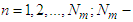
- The size and cost of modern spacecraft vary depending on the application. Some of them can be hold in one hand, whereas others, like Hubble, are as large as a lorry. All small satellites class focus on device with the mass less than 180 kilograms and approximately the dimension of a large kitchen fridge [1]. Small satellites, such as CubeSats, are gradually being used to implement operations conservatively permitted to greater satellite systems.Modern CubeSats are a special class of nanosatellite. The size of one-unit (1U) CubeSat is 10 cm x 10 cm x 11 cm. CubeSats can be composed as made in several combinations of the 1U to form up to 6U (Fig. 1), or even more. Universities, governments and manufacturers are progressively turning to CubeSats as ready-to-build systems able to deliver low-cost and rapid entree to space aimed at research and development along with operative missions such as earth observations, deep space and asteroid captures. Nevertheless, the market of components and hardware for small satellites, mainly CubeSats, still drops small of providing the essential capabilities required by continually growing mission tasks. Diverse CubeSat components are commercially available as off-the-shelf standard components delivered by a restricted quantity of suppliers. A way to overcome this issue is to improve the capacity to adapt each micro-satellite. With the adoption of advanced manufacturing (3D-printing) techniques such as additive manufacturing, some mission specific capabilities can be effortlessly fabricated into a system that commercial off-the-shelf components may not be able to provide, in terms of affordable optimized method [2].
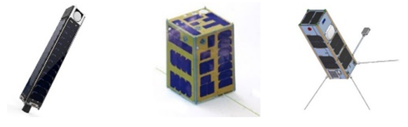 | Figure 1. Different CubeSat examples |
2. Concept of the Design Process
- In terms of knowledge of manufacturing works in the process of CubeSats expansion, design and calculation stages, growth of logic and electric diagrams and improvement computation plans, modeling and analyses have to carried out. The design and the modeling processes include the following stages [1]:1) design and strength inspection and calculations; 2) mass and momentum of inertia calculations, 3) define location centre of mass and the main inertia axes;4) thermal calculations;5) calculations of internal and external disturbing moments CubeSat prompting;6) gas setting calculations for hermetic sections;7) estimation of possibility of meteorite effect and erosion of external surfaces;8) estimation of radiation exposure for devices, glass, coatings and structural non-metallic elements;9) dynamic analysis purposed to control necessities or to check the structure stiffness and action of the orientation system;10) ballistic design;11) power supply system calculations, orientation system and other system designs. The principal focus of this research paper is the CubeSat centre of mass movement stabilization system in the lateral plane applied during the trajectory correction phases. Additionally, a high-thrust sustained propulsion system can be used only if by opposing or linearly moving combustion chamber shall be using in the correction stage to control CubeSat motions [4].Considering the design process in terms of the product development stages [5,6], such process should cover of the technical specification related to CubeSat, development of draft proposal, conceptual and its technical design. It is obvious that in the process of CubeSat design the basic parameters of systems, trajectory characteristics, operation program and the structure design should be putting into account [1].
3. Physical Relationships during Design Process
- The study of physical affiliations in the design process is essential to finding optimum design and compatibility of elementary characteristics of CubeSat. The initial task is to be resolving during the development of any mission [7,8]. Taking into consideration small cost of contemporary CubeSats and the existing approaches of test and control it is hard to imagine that the parameters of any systems could be incompatible in CubeSat, or even could not deliver for the action of its devices [9-11]. The second of the tasks set is examine for optimal combinations of parameters and characteristics. It is more difficult than the initial one and it is not always resolving. This is mostly because of complication of these studies [12-15]. In the simplest occasion, the trajectory and the orbit active launch vehicle shall be set. It should be defining the CubeSat total mass
 to be injecting on the stated trajectory. In this case the scientific equipment’s mass
  will be
 | (1) |
 the entire mass of the facility systems, frame and on-board cables network, required to confirm the CubeSat mission.Hence, in the simplest case, when set the flight mission, or slightly trajectory varying of, or the launcher is choosing, the assignment of optimum design is decreasing of the total mass of service systems, including frame and the on-board cable network. In this circumstance the CubeSat original mass can be seeing as assessment design.If the value
  in equation (1) cannot be considered a self-regulating value, sometimes that expression can be presented as [16]:
  | (2) |
 the total mass of the CubeSat service systems and the frame self-governing of the weight of the scientific equipment;
  is an extra service systems weight and the CubeSat frame, needed for operation of the scientific kit depending on its own weight, configuration and mission task.If the expression
  is simple enough, the appearance (2) can be solving relative to the value
  In this case from equation (2) possible find the next expression [1]:
 | (3) |
 directly. If moving to the minimum of the value
  in the expression (3), i.e. neglect the scientific equipment mass, it also can be estimated, like the service systems that ignored during the design process, and can afford a minor value
  than the picked one [16].In case of probability of a CubeSat perfect operation within a specified time
  as
as  , it can be rewriting in next form [1]:
 | (4) |
 the restricted set of basic system parameters;
  the system number;
  a parameter number;
  parameters set defining the CubeSat trajectory;
  parameter set shaping the action mission.The probability of SmallSats perfect operation shall be defining by the reliability of its separate structures. We shall letter that the minimum amount of CubeSats matches to the minimum cost of the problem solving or the minimum time to complete the total mission. These expressions will include some constants, and so our equations and inequalities shall be writing as follows [1]:
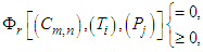 | (5) |
 the number of basic parameters of the
  th system;
  a number of on-board systems;
 If all the terms (5) are equations and
  then the job of looking for optimal parameter values is restricting to finding a constrained extremum of the many variables function. The relations of form (5) are at once the restriction equations [17].The task of rational design is to create a project of a CubeSat for which the rate of the selected criterion is adjacent to the maximum or minimum value. In that case, different configuration diagrams, different orientation patterns and different methods of creating control and corrective forces, etc. should be considering [17]. Depending on the design solution versions the purposes could be change. Thus, the rational design shall be keeping to the study of the function in the restriction equations (5) for diverse versions of the newly designed CubeSat [1].
4. CubeSat Structure Design and Modelling
- The structural design process is an iterative engineering process. The process books for the coming essential variations growing from the interaction among the subsystems [18].In Fig. 2 showed a comparatively old CubeSat example [19]. It is the structure of the metal shell of an entire, only a square opening in the top, which is using to put circuit board and the load into the CubeSat, meanwhile the side covers with a little humble flat solar panels, used to convert and store solar energy into electricity supplied to the CubeSat. Its total mass up to 1 kg, but its metal shell takes up a lot of weight, which means it cannot carry a many of payload. It is clearly that designer want to require a bigger payload. Such design turns counter to our goals, so this is inefficient option.
 | Figure 2. Example of CubeSat structure [19] |
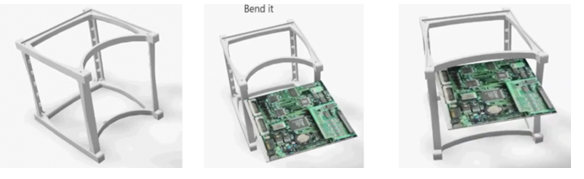
 | Figure 3. Example of CubeSat structure with removable side panels [20] |
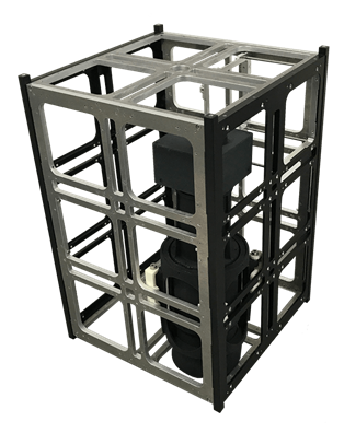
 | Figure 4. Example of 1U CubeSat platform structure conceptual design |
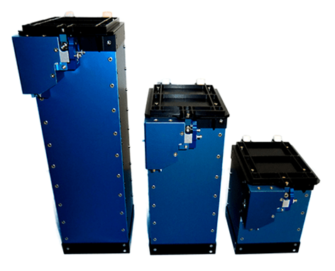 | Figure 5. ISIS ISIPOD 3-Unit CubeSat deployed [23] |
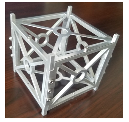
 | Figure 6. Innovative CubeSat A2 2015 structure [24] |
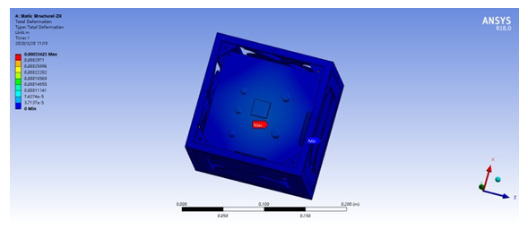 | Figure 7. 1U CubeSat platform design analysis |
5. CubeSat Platform Manufacturing Technique Analysis
- One of the reasons for CubeSats is capitalize on the commercial of-the-shelf (COTS) components that can be used to this type of satellite manufacture. This means that preferably the CubeSat designers are construct least probable quantity of parts. This impression reinforced by assuming that some parts of appropriate feature can be achieving at costs fewer that their internal manufactured equivalents, even if those COTS components are not enough fitting [25].Therefore, here have been serious efforts to list CubeSat’s state-of-the-art components [26] and report the estimated progress of knowledge relevant to CubeSats platforms design and manufacturing [27]. The choice of criteria for such COTS components must depend on flight tradition and the outcomes of a detailed confirmation and validation processes. Concerning the first reason, the extra flight times that a module can prove lacking a failure, the further reliable it is. Element suppliers do not typically offer complete reliability data, but they fix deliver the quantity of positive missions. Such a quantity can be cast-off as an alternative amount to the component reliability, particularly considering the great degree of CubeSat newborn death. A statistical study and a reliability valuation platform model for CubeSats are show in publication [28]. Without respect to the second reason, the design and manufacturing group may rise the components reliability by testing them in appropriate surroundings at the initial stages of the process development. For this persistence, the hardware-in-the-loop simulation techniques consumption for mentioned group of satellites suggested in the next publications [29,30]. In such imitations, prototyped components can be combined with other components, and tested in contrast to their specifications over some error injection. During advanced steps, a completely integrated system could be validating in a related style. must be beyond 70–90 Hz.
6. Results and Discussion
- The estimated structures been realized by using a rapid prototyping technique. That choice allows designer to optimize a CubeSat design, manufacture, and assembly.Grounded on the selected materials and the connecting fastens of both the plastic (ABS) CubeSat platform (Fig. 8), as well as the CubeSat kit reference construction (Fig. 9) made of aluminium, the masses of the structures were calculated and estimated. Results show that reference aluminium structure has a mass of 158 g, however the composite one has an entire mass of 105 g. That means that the composite structure, despite the point that no cuts have been made yet, is nearly 30% less than the aluminium one.
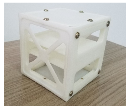 | Figure 8. Plastic (ABS) 1U-CubeSat platform |
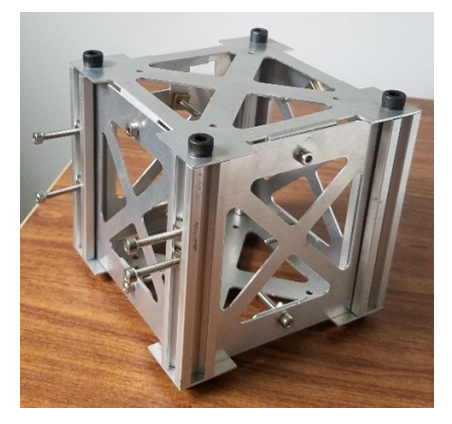 | Figure 9. CubeSat kit reference construction |
7. Conclusions
- This publication reviews CubeSat technology delivers samples of their scientific impact and defines the design and the manufacturing of a 1U-CubeSat platform. Typical CubeSat design process is contained of choice of its trajectory, determination of components and key parameters, systems, development of external and internal designs, and determination of their main features. Proposed paper will emphasis on estimating a concept and physical relations in the design process, and on the rational design algorithm version. In terms of specialization of engineering works throughout SmallSats class development, was formulated concept of the design process and established physical affairs to find some optimal design solution, compatibility of basic parameters and their characteristics.One of the first goal of this study was to design, analysis, and manufacturing technique for 1U CubeSat structures. After study several 1U CubeSat structures platforms, was proposed the basic structural design. That means that preferably the CubeSat platform designers are construct least probable quantity of parts.Except 1U-CubeSat structure was presented the design philosophy to be used in the future mission. In the direction of this end, the designed structure affords the desired flexibility to support settlements.In this search, the use of plastic materials, like ABS, was investigated in the design of 1U-CubeSat platform structures. As a result, experimental 1U-CubeSat platform has been developed, designed for student education, low cost realization and some applied research. The system contains ground-breaking solutions, possibly improving the general performance, and flexibility.