-
Paper Information
- Paper Submission
-
Journal Information
- About This Journal
- Editorial Board
- Current Issue
- Archive
- Author Guidelines
- Contact Us
International Journal of Aerospace Sciences
p-ISSN: 2169-8872 e-ISSN: 2169-8899
2019; 7(1): 13-19
doi:10.5923/j.aerospace.20190701.02

Partially Invariant System for Spacecraft Center of Mass Motion Stabilization
 Abstract
 Reference
 Full-Text PDF
 Full-text HTML
Nickolay Zosimovych
Intelligent Manufacturing Key Laboratory of Ministry of Education, Shantou University, Shantou, China
Correspondence to: Nickolay Zosimovych, Intelligent Manufacturing Key Laboratory of Ministry of Education, Shantou University, Shantou, China.
| Email: |  |
Copyright © 2019 The Author(s). Published by Scientific & Academic Publishing.
This work is licensed under the Creative Commons Attribution International License (CC BY).
http://creativecommons.org/licenses/by/4.0/

This publication suggests how we can improve the spacecraft centre of mass movement stabilization accuracy in the active phases of trajectory correction. It will be during interplanetary and transfer flights, which in some cases provides for high navigation accuracy, when rigid trajectory control method is used. The required stability conditions obtained are consistent with the known criteria in the invariant theory. Computer modelling shows that in a partially invariant stabilization system reveals the significant advantages of such a system in terms of greater accuracy when compared to known stabilization systems.
Keywords: Operating device (OD), Feedback (FB), Control actuator (CA), Control system (CS), Angular stabilization (AS), Centre of mass (CM)
Cite this paper: Nickolay Zosimovych, Partially Invariant System for Spacecraft Center of Mass Motion Stabilization, International Journal of Aerospace Sciences, Vol. 7 No. 1, 2019, pp. 13-19. doi: 10.5923/j.aerospace.20190701.02.
Article Outline
1. Introduction
- The thriving space technology is characterized by an increasing complexity of the tasks to be solved by modern space vehicles (SV) [1].Except improvement of the navigational accuracy, reduction of spacecraft stabilization cross errors in the active phase, it also results in lower total characteristic velocity of corrective impulses, and, consequently, in reduction of fuel required for the correction. When the correction speed impulse reaches 30 reduction of gross error during the correction manoeuvre results in proportional reduction of the required characteristic velocity during the next correction. The data referred to in publications [2,3] show that improved accuracy of roll stabilization in the active phase by one order results in reduction of total characteristic correction velocity for Mars interplanetary probe from about 20 m/sec to 2 m/sec. This is corresponds to fuel savings up to 30 kg, or to increase of the payload mass. Due to the relatively small weight of modern scientific instruments (about 3-8 kg), even such small increase of payload weight can significantly extend the program of research and experiments implemented by the spacecraft [1].Objectives: Solution the task of significant increase in stabilization accuracy of centre of mass tangential velocities during the trajectory correction phases when using the "rigid" trajectory control principle.Since the time of the active phase in correction manoeuvres, (which is to be determined by the required velocity impulse) shall not be clearly determined in advance, and quite limited. This is because of guaranteed approach enabling to estimate the accuracy, is always used in practice for solving the targeting tasks, and we shall understand the maximum dynamic error of the transition process as concerns the drift velocity of the spacecraft to mean the accuracy of the spacecraft centre of mass movement stabilization [4].Subject of research: The centre of mass movement stabilization system in the transverse plane during the trajectory correction phases.The angular stabilization channel facilitates angular position of the spacecraft when exposed to disturbing moments. The centre of mass movement stabilization channel is to ensure proximity to zero of normal and lateral velocities of the spacecraft under the influence of disturbing moments and forces. In most of the known spacecraft stabilization systems [5-7] the control signal in the centre of mass movement stabilization channel is generated according to proportional plus integral control law based on the measurements of tangential velocity of the centre of mass
 and its integral-linear drift
  In the angular stabilization channel, the control signal shall be generated in proportion to the spacecraft deviation angle, in the transverse plane
  and the angular velocity of the spacecraft rotation in this plane
  .The required dynamic accuracy of stabilization of tangential velocities in this system shall be achieved through the choice of the gain in the stabilization controller
  If the requirements to the accuracy of centre of mass movement stabilization are stiff, the coefficients
  and
and  shall be necessarily significantly increased [5].To improve the correction accuracy, the following additional algorithm shall be used in practice. The improvement of accuracy in this case shall be achieved by partial compensation of the main disturbing factors [1]: eccentricity and thrust misalignment in the propulsion system already in the initial moment of operation of the propulsion system. This algorithm is based on the assumption that eccentricity and thrust misalignment in PS change slightly towards the end of the active phase during the previous correction, and PS setting before a new active phase sets in progress, ensures that the thrust vector goes approximately through the centre of mass of the spacecraft, thereby considerably offsetting the disturbing moment.A similar algorithm was applied in the stabilization system of the Apollo spacecraft [7].The stabilization systems of Titan IIIC, Kosmos-3M launchers also used subsystems tracking the centre of mass positional history, and providing the thrust vector's passage through the centre of mass [8].It should be pointed out that the process of implementation of the described algorithm is confronted by a number of challenges [9]:• Difference in disturbing factors (moments and forces) during the previous and subsequent corrections results in additional errors (in the stabilization) of the tangential velocities of the spacecraft centre of mass.• Due to the limited time of the active phase, deactivation of PS during the previous correction may occur even before the completion of the transition processes, and as a result, the system will remember the deviation of the steering control, which was not final.Besides introduction of additional control algorithms, there are other ways to increase the accuracy of the centre of mass movement stabilization. It is a commonly known fact that one of the ways to achieve high accuracy in automatic control systems, is to use the so-called invariant theory [10-12]. The theory was developed by G.V. Shchipanov (1939), a Soviet scientist, who formulated the task "on compensation of external disturbances". Now, thanks to research conducted by the Soviet scientists G.V. Shchipanov, B.N. Petrov, V.S. Kulebakin, A.I. Kukhtenko and others the invariant theory represents a developed approach in the general theory of automatic control [9].One of the problems inherent in the synthesis of invariant control systems, is the ability for the implementation of such systems in most cases through the use of the deviation control principle, as the simplest one and most widely used in practice. The publications [13-15] consider the possibility of constructing an invariant deviation control system with one adjustable parameter including an inertial element and a servo control with feedback. The general provisions of the invariant theory prove that no absolutely invariant system can be implemented in this case because this requires that the circuit with feedback should have an infinitely great gain.As a rule, most invariant control systems are based on the use of the information about external influences. Such control systems belong to the class of combined regulatory systems. In particular, the combined systems constitute the majority of invariant systems [16-22].There is still another method to enforce implementation of invariance conditions without application of combined regulatory techniques [23]. To implement such a system, it is necessary that two influence distribution channels should be present in the controlled element.Meeting the conditions of partial invariance significantly reduces interaction between the angular stabilization channels and the centre of mass movement stabilization channel, which is applied in practice [7,22,24-29] and does not allow significant improvement of stabilization accuracy of the spacecraft drift velocity.The publication provides analysis of stability of the synthesized control algorithms, proves availability of stability margins in partially invariant systems sufficient for practical implementation [16].In some spacecraft, we may use an operating device with a linear movement of PS (Fig. 1). In such an activation device, PS chamber shall move linearly in the normal (side) plane relative to the X-axis of the spacecraft. The advantage of such an operating device is that any linear acceleration is absent during linear movement of PS chamber perpendicular to the X-axis of the spacecraft, which can significantly improve the accuracy of tangential velocities.
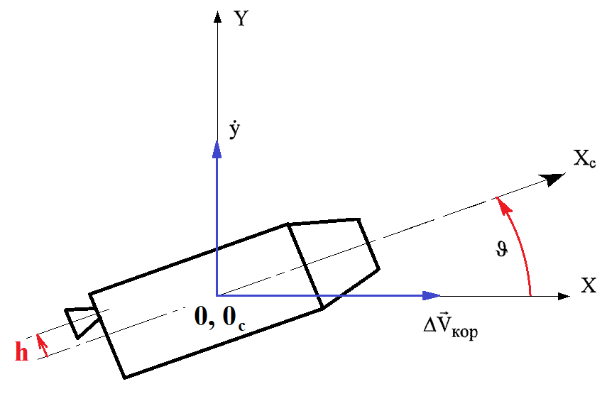 | Figure 1. Spacecraft with linear movement of PS in the inertial coordinate system |
2. Partially Invariant Spacecraft’s Stabilization System Using an Operating Device with a Linearly Moving Combustion Chamber of PS
- Thus, as in the case of the stabilization system with rotation of OD, the conditions for partial invariance of the center of mass tangential velocity relative to the disturbing moment and the disturbing force shall be the lack of feedback from the control actuator and the absence of an error signal about angular deviation of the object.Let us consider the stability of such a system in more detail. The characteristic equation of the system taking into account the invariance conditions shall be as follows (excluding dynamic delay of the stabilization controller):
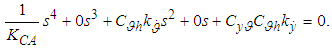 | (1) |
 and from the center of mass drift velocity derivative
  into control action. In which case the characteristic equation shall be:
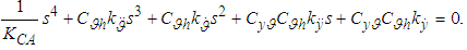 | (2) |
 does not lead to a decrease in the order of the characteristic equation, and, consequently, a sufficient degree of stability of the system can be provided by selecting the parameters of the control action. The block diagram of the stabilization system with linear movement of OD corresponding to the equation (2) is presented in Fig. 2.
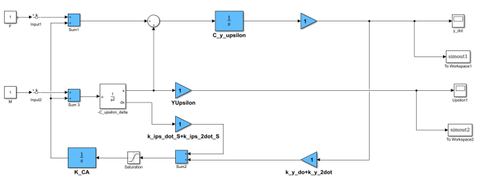 | Figure 2. Block diagram of a partially invariant spacecraft centre of mass stabilization system with linear movement of OD |
3. Modeling Transition Processes in a Partially Invariant Spacecraft Center of Mass Motion Stabilization System with Linear Movement of the Operating Device
- To compare the accuracy of the spacecraft transverse velocities stabilization while using standard and invariant control algorithms in the stabilization system with linear movement of PS we shall do mathematical modeling. In this case, the modeling is performed in a similar way to the modeling for the stabilization system with the rotation of PS [31-35]. The differences relate only to the mathematical model of the control object, which according to the system of differential equations (2) and the block diagram (Fig. 2) for the spacecraft under consideration shall be as follows:
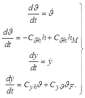 | (3) |
 h:
h: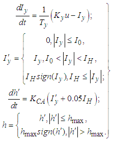 | (4) |
 , and the disturbing force by the equivalent angle of deviation of spacecraft's X-axis
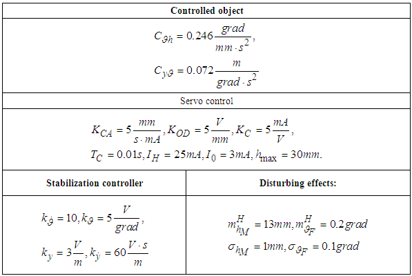
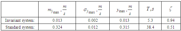
  .For the modeling we took real parameters of the stabilization system of the simulated automatic interplanetary station of the type [36] corresponding to the third, final correction section (Table 1) as parameters for the control object, servo control, disturbances and stabilization controller (for a standard system). The parameters for the stabilization controller for the invariant system (Table 2) were chosen according to the method described in [36]. The choice of these parameters for the referred spacecraft is described in [37]. The values of these parameters for the invariant and standard stabilization systems obtained because of modeling are presented in Table 3.
|
|

|
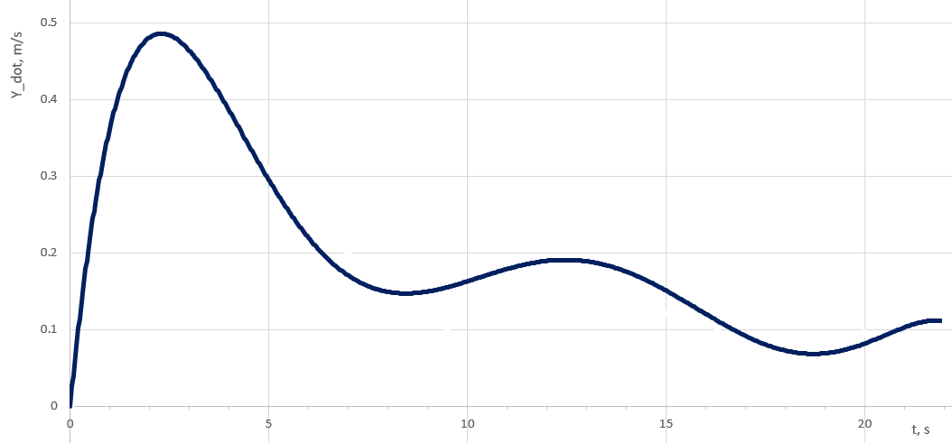 | Figure 3. Spacecraft drift velocity transition processes in the normal plane in a standard stabilization system (deterministic model) |
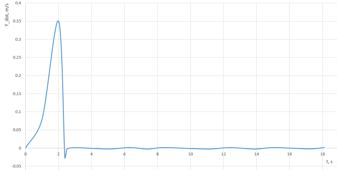 | Figure 4. Spacecraft drift velocity transition processes in the normal plane in an invariant stabilization system (deterministic model) |
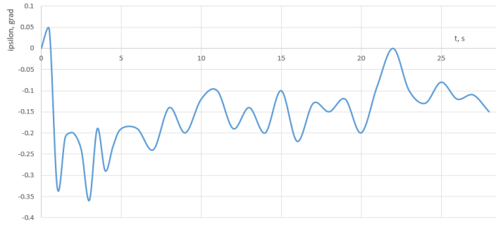
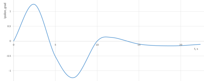 | Figure 5. Spacecraft X-axis angular deviation transition processes in the normal plane in a standard stabilization system (deterministic model) |
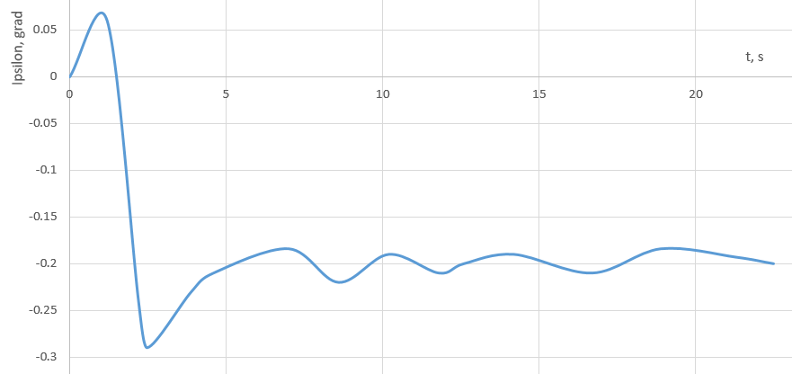 | Figure 6. Spacecraft X-axis angular deviation transition processes in the normal plane in an invariant stabilization system (deterministic model) |
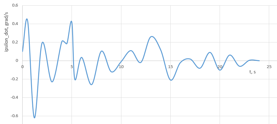
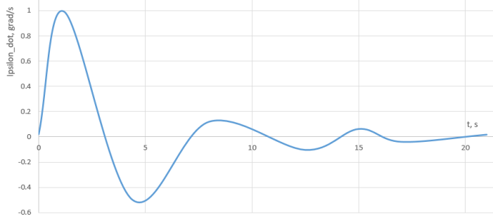 | Figure 7. Spacecraft X-axis angular deviation transition processes in the normal plane in a standard stabilization system (deterministic model) |
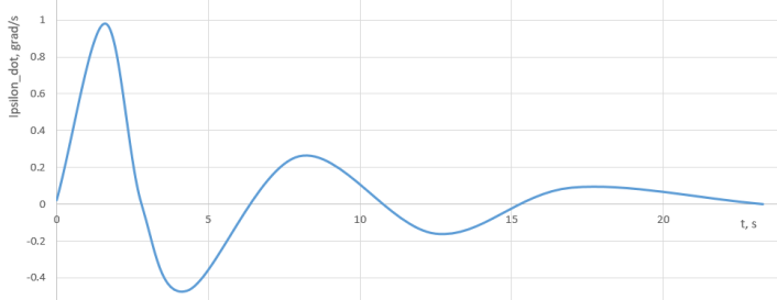 | Figure 8. Spacecraft X-axis angular deviation transition processes in the normal plane in an invariant stabilization system (deterministic model) |
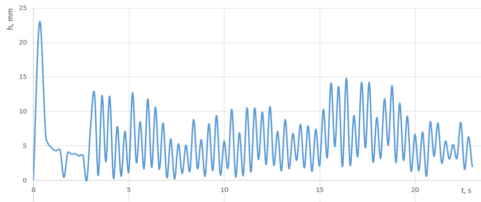
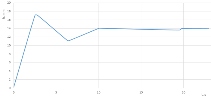 | Figure 9. The spacecraft operating device linear movement transition process in a standard stabilization system (deterministic model) |
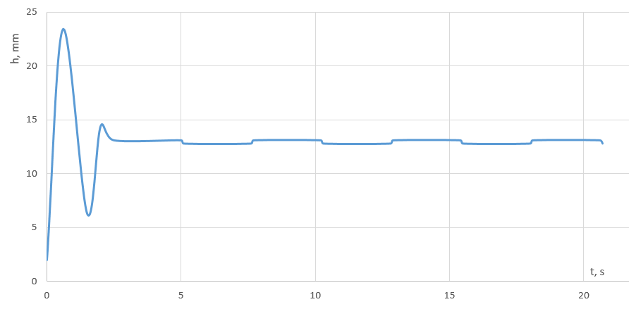 | Figure 10. Spacecraft operating device linear movement transition process in an invariant stabilization system (deterministic model) |
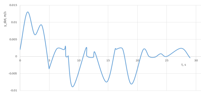 | Figure 11. Spacecraft drift velocity transition processes in the normal plane in an invariant stabilization system (deterministic model) |
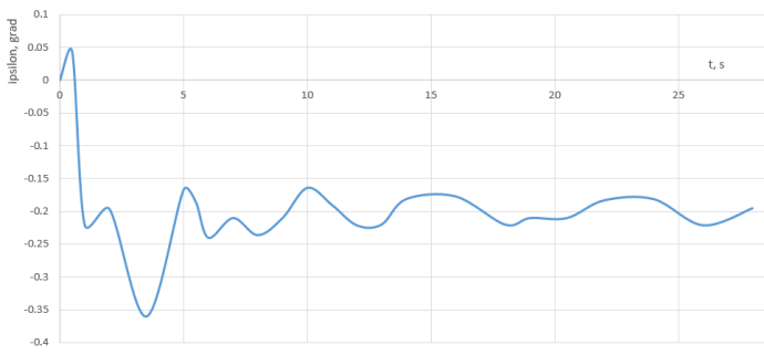 | Figure 12. Spacecraft X-axis angular deviation transition processes in the normal plane in an invariant stabilization system (deterministic model) |
 | Figure 13. Spacecraft X-axis angular deviation transition processes in the normal plane in an invariant stabilization system (deterministic model) |
 | Figure 14. Spacecraft operating device linear movement transition process in an invariant stabilization system (deterministic model) |
 | Figure 15. Spacecraft operating device linear movement transition process in an invariant stabilization system (deterministic model) |
4. Discussion
- Now let us consider the question of choosing parameters for the stabilization controller ensuring minimization of the maximum dynamic error, drift velocity under the requirements of sufficient stability margins [35]. As general view of the stability region for the stabilization system with linear movement of PS coincides with the general view of the stability region for the stabilization system with rotating PS, we can apply the algorithm described in publications [2-7] to select stabilization controller parameters. Because of application of the specified algorithm with stable solutions for the partially invariant centre of mass motion stabilization system for China's HX-1 Mars Mission Spacecraft type [31] was made.The stability analysis approximately the selected operating point
 for the angular stabilization channel (Step of the parameter selection algorithm) [34] also confirm the presence of sufficient stability margins. The position of the selected parameters for the stabilization controller in respect to the stability boundary of the system is shown in Fig. 16-17.
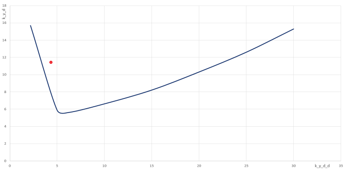 | Figure 16. Position of the selected parameters for angular stabilization channel with respect to the stability boundary of the system |
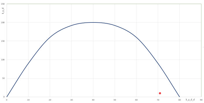 | Figure 17. Position of the selected parameters for the centre of mass movement stabilization channel with respect to the stability boundary of the system |
5. Conclusions
- The invariance conditions for the spacecraft centre of mass stabilization system with linear movement of the operation device are the absence of feedback from the control actuator and the absence of a member in the control action proportional to the angular deviation of the spacecraft. To ensure stability, it is necessary to introduce members proportional to the angular and linear acceleration of the spacecraft into the control action.Because of mathematical modeling of transition process in stabilization system of HX-1, (which is currently used and the proposed invariant system) it has been found that the dynamic error of the centre of mass tangential velocity stabilization is one order less in the invariant stabilization system as compared to the system used. The centre of mass tangential velocity transition process has much shorter decay time in the invariant system as compared to the transition process in the system used.It has been found as a result of stability study that the system under consideration can provide for the required (for practical implementation) stability margins when high accuracy of centre of mass tangential velocity stabilisation is achieved (in the invariant stabilization system) both in linear terms and taking into account the nonlinearity of the control actuator. The nonlinearity of the control actuator of "saturation zone” type results in an unstable limit cycle. Because of this, the stabilization system becomes conditionally stable.