Mohamed A. Fouad Kandil, Abdelrady Okasha Elnady
Mechatronics Department, Faculty of Engineering, October 6 University, Egypt
Correspondence to: Mohamed A. Fouad Kandil, Mechatronics Department, Faculty of Engineering, October 6 University, Egypt.
| Email: |  |
Copyright © 2017 Scientific & Academic Publishing. All Rights Reserved.
This work is licensed under the Creative Commons Attribution International License (CC BY).
http://creativecommons.org/licenses/by/4.0/

Abstract
In this research, CFD analysis of the two-dimensional subsonic flow over a GOE 387 airfoil at various angles of attack and operating at a Reynolds number of 3 x10⁵ is presented. Pressure distribution, Pressure Coefficient (Cp), Moment Coefficient (Cm) Lift Coefficient (Cl), and Drag Coefficient (Cd) are determined. The geometry of the airfoil is created using ANSYS Design Modeler. CFD analysis is carried out using FLUENT 17.2 at various angles of attack from -5° to 20°. Pressure distributions over GOE-387 airfoil for different angles of attack are presented. Moment coefficients and pressure coefficients are plotted against the angle of attack. Cl-Cd graph is plotted.
Keywords:
Airfoil, Angle of Attack, CFD, Moment Coefficient, Pressure Coefficient, Lift, Drag
Cite this paper: Mohamed A. Fouad Kandil, Abdelrady Okasha Elnady, Performance of GOE-387 Airfoil Using CFD, International Journal of Aerospace Sciences, Vol. 5 No. 1, 2017, pp. 1-7. doi: 10.5923/j.aerospace.20170501.01.
1. Introduction
In the early 1800s, Sir George Cayley discovered that a curved surface produced more lift than a similar sized flat plate. What aviation pioneers discovered, which still holds true today, is that the most efficient way to do this is to use a curved, streamlined shape—the airfoil.Airfoil is defined as the cross-section of a body that is placed in an airstream in order to generate useful aerodynamic force. The Wright brothers, many of the early designers used “eyeball engineering” in developing or copying the airfoil shape used on their airplanes. From about 1912, airfoil development and research moved to the wind tunnel laboratories found at the University of Göttingen in Germany, the Royal Aircraft Factory in the United Kingdom, and the National Advisory Committee for Aeronautics (NACA) in the United States. Since then, the wind tunnel, complex mathematics, and the computer have all played important roles in airfoil development.For the last three decades, Computational Fluid Dynamics (CFD) has fascinated researchers, as it is a fast, accurate and reliable method of analyzing the variation of hydrodynamic properties of the flow over and within a body. Computational Fluid Dynamics (CFD) is a branch of fluid mechanics that uses numerical methods and algorithms to solve complex problems involving fluid flow.Some of the recent interesting work in the study of airfoils has been discussed below. Patel, Karna S., et al [1] have obtained the drag and lift forces using CFD. Kevadiya, Mayurkumar [2] investigated NACA 4412 airfoil at various angles of attack from 0° to 12° using CFD analysis. Variations of pressure coefficient are plotted in form of contour for 1 ×10⁵ Reynolds number.Patil et al. [3] investigated the effect of low Reynolds number on lift and drag for the wind turbine blade. They found out as Reynolds number increases, lift and drag forces increases. Haque et al. [4] conducted various experimental studies to understand the effects of Reynolds number and angle of attack in flow analysis. Yao et al. [5] studied the aerodynamic performance of wind turbine airfoils and compared the numerical results with experimental data. The effect of transonic flow over an airfoil has been studied and a comparative analysis has been was done to analyze the variation of the angle of attack and Mach number [6]. Kandil and Elnady present a CFD analysis of GOE 387 airfoil [7].In the light of the review of the existing literature, the present study aims to analyze the flow field for GOE 387 airfoil at various angles of attack with constant Reynolds number of 3 x10⁵. The flow was obtained by solving the steady-state governing equations of continuity and momentum conservation with Transition k-kl-omega turbulence model.Pitching moment coefficient (Cm):The pitching moment coefficient (Cm) is the moment (or torque) produced by the aerodynamic force on the airfoil if that aerodynamic force is considered to be applied, not at the center of pressure, but at the aerodynamic center of the airfoil. where M is the pitching moment, q is the dynamic pressure, S is the wing area, and c is the length of the chord of the airfoil. Cm is a dimensionless coefficient so the consistent unit must be used for M, q, S, and c.Pressure Coefficient Cp:Cp is the difference between local static pressure and free-stream (at ∞) static pressure, nondimensionalized by the free-stream dynamic pressure. At any point in the flow where the local pressure coefficient Cp is defined as
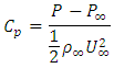 The Total or Stagnation Upstream Pressure PT is the sum of the static and dynamic pressure at that point according to Bernoulli's equation:
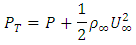 Thus, CP may also be written in terms of the differential pressures as
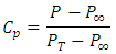 CP, at the airfoil stagnation point, is unity.
2. Geometry and Mesh Generation
The geometry of GOE 387 is shown in Figure 1. For discretization of the computational domain, an unstructured mesh with the body of influence centered on the airfoil and rectangular path were selected. The mesh used for the analysis is shown in Figures 2 and 3, Pressure based steady-state solver with Transition k-kl-omega turbulence model is used for analysis.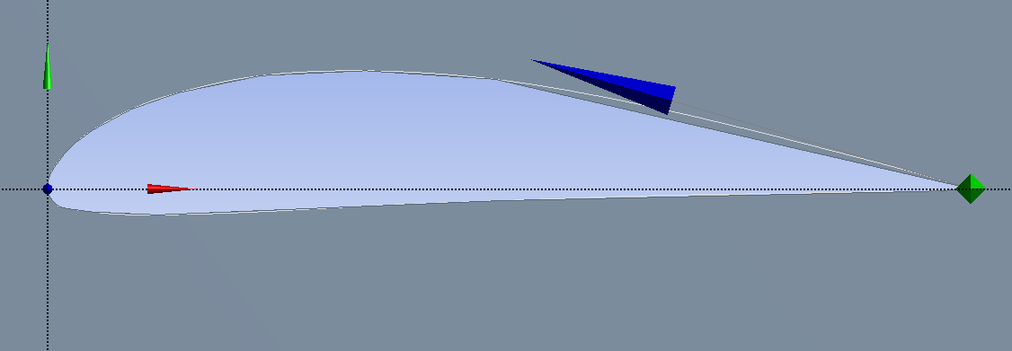 | Figure 1. Geometry of GOE 387 Airfoil |
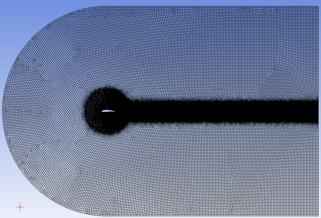 | Figure 2. Completed Mesh |
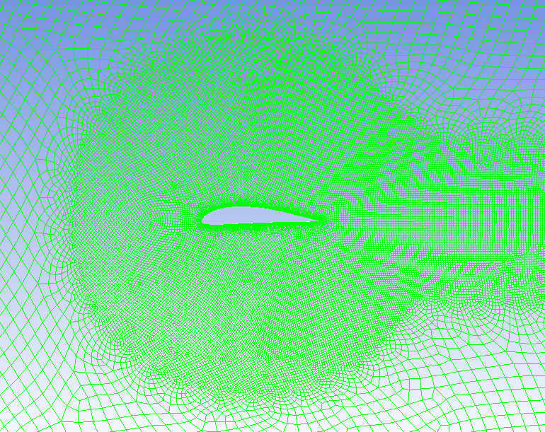 | Figure 3. Mesh of the computational domain |
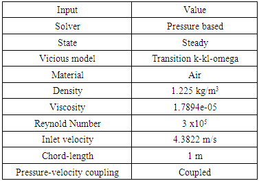
3. Inputs and Boundary Conditions
The problem consists of flow around an airfoil at various angles of attack (-5, 0, 5, 10, 15, 20 degrees). The inputs and boundary conditions are presented in Table 1.Table 1. Inputs and boundary conditions
 |
| |
|
4. Results and Discussion
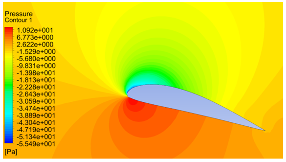
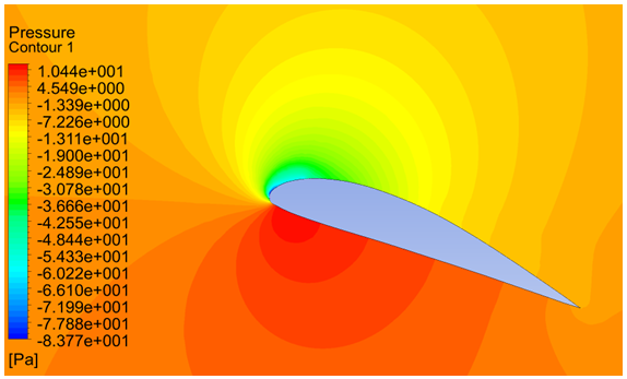
4.1. Contours of Pressure Magnitude
The contours of pressure magnitude obtained for various angles of attack from CFD simulations are shown in Figures 4, 5, 6, 7, 8 and 9. The flow accelerates on the upper side of the airfoil and the velocity of flow decreases along the lower side, according to Bernoulli’s principle the upper surface will experience low pressure and the lower surface will experience higher pressure. As the pressure on the lower surface of the airfoil is greater than that of the incoming flow stream, the airfoil is effectively pushed upward normal to the incoming flow stream.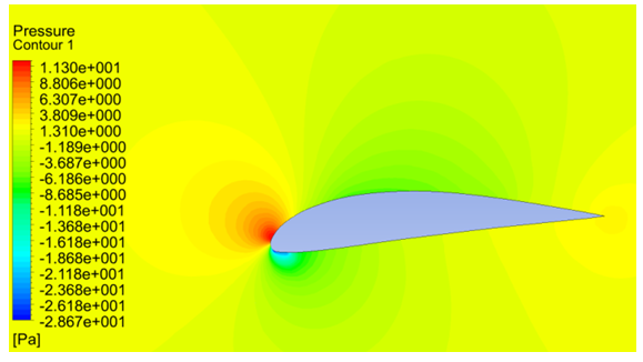 | Figure 4. Pressure contours at -5 degrees of angle of attack |
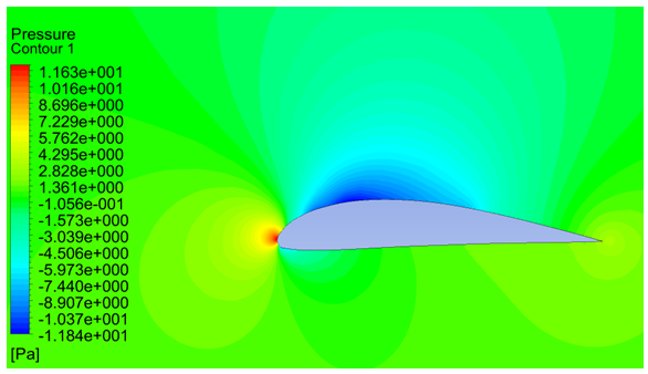 | Figure 5. Pressure contours at 0 degrees of angle of attack |
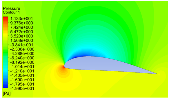 | Figure 6. Pressure contours at 5 degrees of angle of attack |
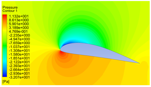 | Figure 7. Pressure contours at 10 degrees of angle of attack |
 | Figure 8. Pressure contours at 15 degrees of angle of attack |
 | Figure 9. Pressure contours at 20 degrees of angle of attack |
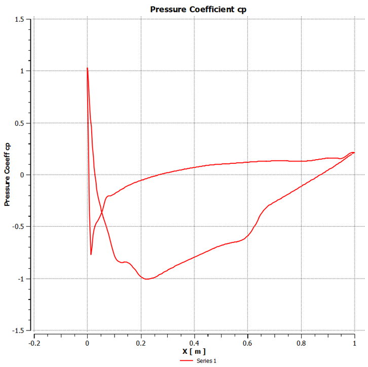
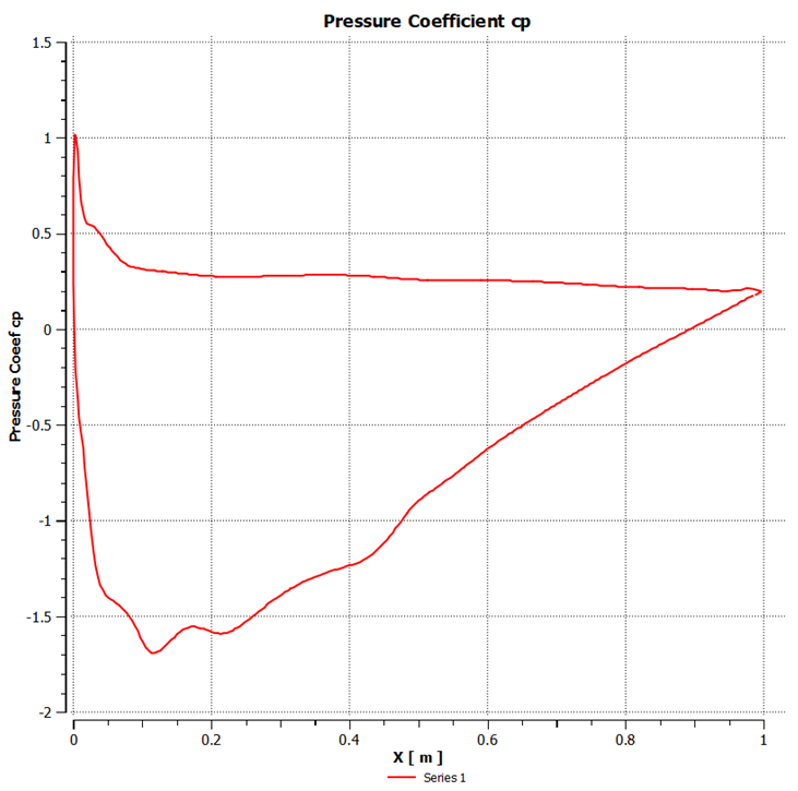
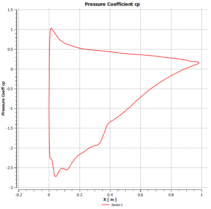
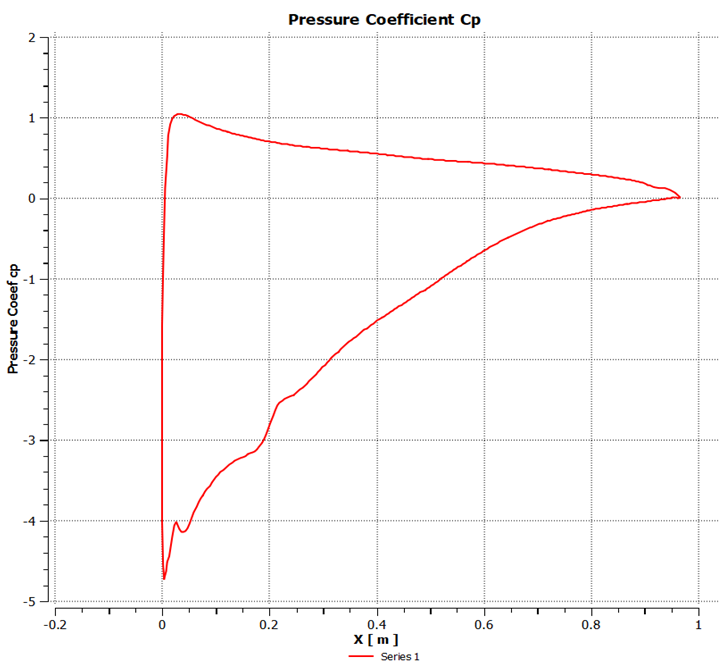
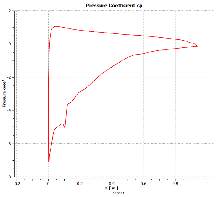
4.2. Distribution of Pressure Coefficient
The distribution of pressure coefficient of GOE 387 airfoil under different angles of attack is shown in the following Figures 10, 11, 12, 13, 14 and 15. It can be seen that the pressure coefficient varied largely under different attack angle. The pressure coefficient of the airfoil’s upper surface was negative and the lower surface was positive, thus the lift force of the airfoil is in the upward direction. Larger the attack angle, greater is the difference of pressure coefficient between the lower and upper surface. We can also see that the coefficient of pressure difference is much larger on the front edge, while on the rear edge it was much lower, thus indicating that the lift force of the airfoil is mainly generated from the front edge.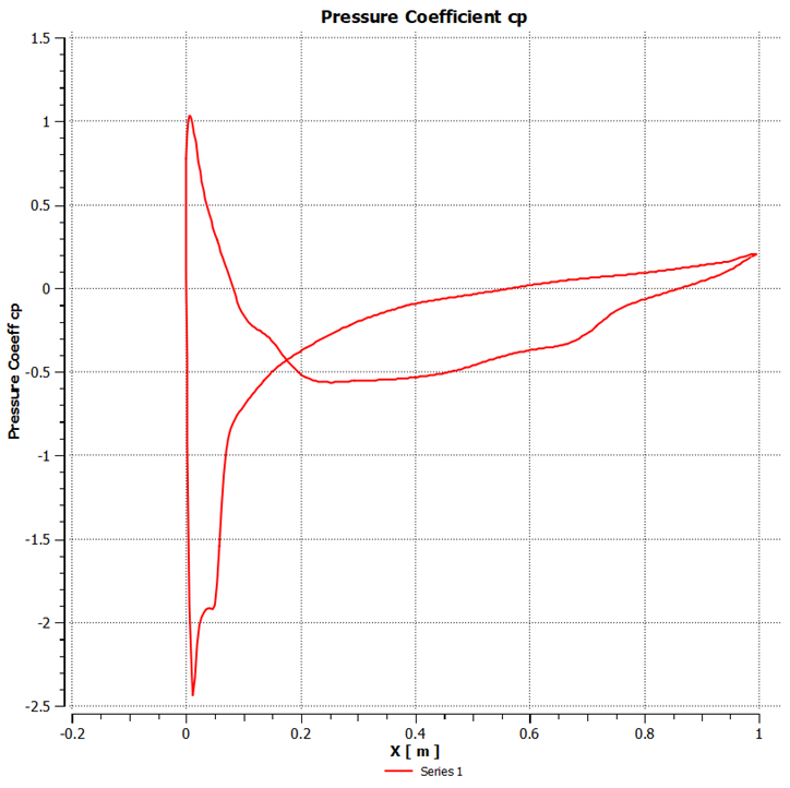 | Figure 10. Pressure coefficient at -5° angle of attack |
 | Figure 11. Pressure coefficient at 0° of attack |
 | Figure 12. Pressure coefficient at 5° angle of attack |
 | Figure 13. Pressure coefficient at 10° angle of attack |
 | Figure 14. Pressure coefficient at 15° angle of attack |
 | Figure 15. Pressure coefficient at 20° angle of attack |
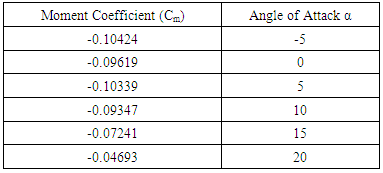
4.3. Curve of Moment Coefficient vs. Angle of Attack
The Moment coefficient is computed at aerodynamic center for various angles of attack using the Transition k-kl-omega model. The results are tabulated in Table 2 and shown in Figure 16.Table 2. Moment Coefficients Cm with Angle of Attack
 |
| |
|
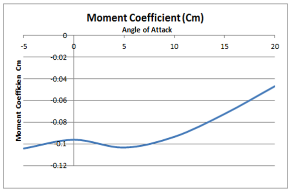 | Figure 16. Curve of Moment Coefficient vs. Angle of Attack |
4.4. Lift and Drag Characteristics
Lift drag characteristics of the GOE-387 airfoil are obtained by plotting Cl against Cd as shown in Figure 17. From this figure, the lift and drag characteristics are summarized as follows: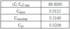
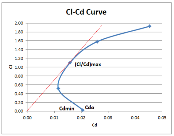 | Figure 17. Curve of Lift Coefficient vs. Drag Coefficient |
5. Conclusions
With the help of CFD software Ansys-Fluent, successful analysis of the aerodynamic performance of GOE 387 airfoil has been carried at various angles of attack (-5, 0, 5, 10, 15, 20 degrees) with constant Reynolds number (3 x10⁵) using the Transition k-kl-omega turbulence model. The pressure coefficient of the airfoil’s upper surface was negative and the lower surface was positive, thus the lift force of the airfoil is in the upward direction. The coefficient of pressure difference is much larger on the front edge, while on the rear edge it was much lower. The moment and force reference point is taken at 25% of Mean Aerodynamic Cord, the magnitude of the aerodynamic moment remains nearly constant when the angle of attack changes.
References
| [1] | Patel, Karna S., et al. "CFD Analysis of an Aerofoil." International Journal of Engineering Research 3.3 (2014): 154-158. |
| [2] | Kevadiya, Mayurkumar. "CFD Analysis of Pressure Coefficient for NACA 4412." International Journal of Engineering Trends and Technology, Chennai 4.5 (2013): 2041-2043. |
| [3] | Bhushan S. Patil, Hitesh R. Thakare, Computational Fluid Dynamics Analysis of Wind Turbine Blade at Various Angles of Attack and different Reynolds Number, Procedia Engineering, 127(2015), 1363-1369 M. Wegmuller, J. P. von der Weid, P. Oberson, and N. Gisin, “High resolution fiber distributed measurements with coherent OFDR,” in Proc. ECOC’00, 2000, paper 11.3.4, p. 109. |
| [4] | Nazmul Haque, Mohammad Ali, Ismat Ara, Experimental Investigation on the performance of NACA 4412 aerofoil with curved leading edge plan form, Procedia Engineering, 105(2015), 232-240 M. Shell. (2002) IEEEtran homepage on CTAN. [Online]. Available: http://www.ctan.org/tex-archive/macros/latex/contrib/supported/IEEEtran/. |
| [5] | Jin Yao, Weibin Yuan, Jianliang Wang, Jianbin Xie, Haifeng Zhou, MingjunPeng, young Sun, Numerical simulation of aerodynamic performance for two-dimensional wind turbine airfoils, Procedia Engineering, 31(2012), 80-86 “PDCA12-70 data sheet,” Opto Speed SA, Mezzovico, Switzerland. |
| [6] | Novel Kumar Sahu, Mr. Shadab Imam, Analysis of Transonic Flow over an Airfoil NACA0012 using CFD, International Journal of Innovative Science, Engineering & Technology, Vol. 2 Issue 4, April 2015 J. Padhye, V. Firoiu, and D. Towsley, “A stochastic model of TCP Reno congestion avoidance and control,” Univ. of Massachusetts, Amherst, MA, CMPSCI Tech. Rep. 99-02, 1999. |
| [7] | Mohamed A. Fouad Kandil, Abdelrady Okasha Elnady, “CFD Analysis of GOE 387Airfoil”, IOSR Journal of Mechanical and Civil Engineering (IOSR-JMCE), Volume 14 - Issue 5, Sep. – Oct. 2017, PP 80-85. |

 Abstract
 Reference
 Full-Text PDF
 Full-text HTML