-
Paper Information
- Previous Paper
- Paper Submission
-
Journal Information
- About This Journal
- Editorial Board
- Current Issue
- Archive
- Author Guidelines
- Contact Us
International Journal of Aerospace Sciences
p-ISSN: 2169-8872 e-ISSN: 2169-8899
2013; 2(3): 138-147
doi:10.5923/j.aerospace.20130203.06
Invasive Weed Optimization for Turbojet Engine Fuel Controller Gain Tuning
 Abstract
 Reference
 Full-Text PDF
 Full-text HTML
S. Jafari, M. Montazeri-Gh
Systems Simulation and Control Laboratory, School of Mechanical engineering, Iran University of Science and Technology, Tehran, Iran
Correspondence to: S. Jafari, Systems Simulation and Control Laboratory, School of Mechanical engineering, Iran University of Science and Technology, Tehran, Iran.
| Email: |  |
Copyright © 2012 Scientific & Academic Publishing. All Rights Reserved.
This paper presents the application of invasive weed optimization (IWO) in Gas Turbine Engine (GTE) fuel controller design. For this purpose, the GTE controller gain tuning process is firstly formulated as an engineering optimization problem based on an industrial Min-Max fuel control strategy. This formulation is then carried out using the IWO method which is a newly developed search based stochastic optimization approach. The feasibility and efficiency of the proposed algorithm for optimization of GTE fuel controller are examined by comparison between IWO results, genetic algorithm (GA) results and the global optimal results obtained from dynamic programming (DP) method. In addition, simulation of the optimized controller confirms the effectiveness of the proposed approach and its ability to design an optimal fuel controller resulting in an improved GTE performance as well as protection against the physical limitations.
Keywords: Genetic Algorithm, Invasive Weed Optimization, Gas Turbine Engine-Fuel Controller, Gain Tuning, Dynamic Programming
Cite this paper: S. Jafari, M. Montazeri-Gh, Invasive Weed Optimization for Turbojet Engine Fuel Controller Gain Tuning, International Journal of Aerospace Sciences, Vol. 2 No. 3, 2013, pp. 138-147. doi: 10.5923/j.aerospace.20130203.06.
Article Outline
1. Introduction
- Gas turbine aero-engines have played an imperative role in the reliable operation of the aircrafts. For safe operation of an aircraft, stable and limit protected operation of its GTE must be ensured. Therefore, design and fine-tuning of an appropriate control system for a GTE is required to provide the satisfactory operation of the aircraft. One of the most complexities of GTE controller design is to set the controller parameters so that the engine runs optimally. On the other hand, the industrial control strategies for GTE usually use the logical selection algorithms resulting in switching and nonlinear functions[1]. Consequently, for tuning process of the controller parameters, the gradient based methods may not result in an optimized engine performance. These approaches need an initial solution which is logically close to the final solution, otherwise they trapped in a local minimum. As a result, this problem requires a non-gradient based optimization technique. In recent decades, a vast variety of non-gradient based optimization methods have been formulated, and some inspired by natural processes. Genetic algorithm[2], particle swarm optimization[3] and ant colony optimization[4] are such methods that have already been used in various real- world optimization problems[5-10]. In addition, Mehrabian and Lucas proposed the Invasive Weed Optimization (IWO) as a novel stochastic, non-gradient based algorithm inspired by the ecological behavior of colonizing weeds in 2006[11]. “In their leading research, Mehrabian and Lucas have shown the merits of IWO in finding global optimum of different complex multi-dimensional optimization problems, which reveals that IWO is an appropriate competitor for other comparatively older and well-established techniques for population-based evolutionary computation.”[12]The aim of the present study is to investigate the use of IWO approach for GTE fuel controller gain tuning for the first time. For this purpose, an industrial fuel controller structure for a turbojet engine is firstly described. The GTE controller gain tuning is then formulated as an optimization problem based on the IWO approach where the objective function is defined to minimize the combination of the engine response time and fuel consumption. Subsequently, the results of the IWO are presented and compared with the global optimal results of dynamic programming (DP) technique in order to assess the effectiveness of the proposed approach for GTE fuel controller gain tuning. Moreover, the IWO results are compared with the results obtained from genetic algorithm (GA) to evaluate the reliability of the proposed method for using as a new metaheuristic optimization method in practical problems. Finally, the effect of optimization process on the engine performance is analyzed to study the improvement of the objective function as well as protection of the engine against physical limitations.
2. Formulation of the Optimization Problem
- In this section, industrial Min-Max fuel controller design for a single spool turbojet engine is firstly described. The objective function is then prepared based on the designed controller in order to apply the IWO method.
2.1. GTE Fuel Controller Structure
- Safe operation of a GTE depends on the satisfaction of its control modes. The GTE control system is designed to fulfill the pilot demand in a reasonable response time without exceeding the engine physical limitations including over-speed, over-temperature, flameout and surge in compressor. In other words, the control of a turbojet engine can be summarized by the following three different modes:● Steady state control mode (to satisfy the pilot demand without error).● Transient control mode (to satisfy the pilot demand in a reasonable response time).● Physical limitation control mode (to protect the engine against over-speed, over-temperature, compressor surge and flameout). Industrial fuel control strategies for a GTE have two main sections including steady-state controller part and transient controller part as shown in Fig.1. The steady-state controller is responsible to compute the steady state fuel flow (
 ) according to the engine operating condition. In this study, this part of the fuel flow is calculated by a scheduling controller as a function of the engine rotor speed. The steady state part of the controller satisfies the first engine control mode i.e. steady state control mode. In addition to the steady-state controller, a transient controller part is considered for the control of the engine transient performance as well as the engine limitations. Transient fuel flow is the variation of the fuel flow with respect to its steady-state value. As shown in Fig.1, the structure of the controller for calculation of the transient fuel flow consists of four control loops as follow:● Pilot lever angle (PLA) control loop; this control loop is responsible to provide the necessary transient fuel flow for satisfying the pilot demand (with gain
  ). This control loop satisfies the second control mode i.e. transient control mode. The response time of the engine mainly depends on the
  variation.
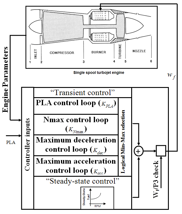 | Figure 1. Schematic of a GTE and fuel controller |
 ).● Maximum deceleration control loop; this control loop is designed to protect the engine against the flameout (with gain
 ).● Maximum acceleration control loop; this control loop takes care of the engine aerodynamic instability including surge or stall occurrence (with gain
 ). It should be noted that surge is a longitudinal flow oscillation over the length of the compressor and turbine and often is due to high rotor acceleration[13]. Thus, the control of rotor speed derivative (
 control) provides surge control. In this study, the limiting bounds for the engine rotor acceleration and deceleration are found analytically and confirmed experimentally[14]. To satisfy all physical limitations, the turbine inlet temperature (TIT) should also be bounded. However, as the thermocouples usually need to shield and their responses are slow, the
  ratio is widely used to control the combustion chamber output temperature as shown in Fig.1.Using this approach, Wf/P3 control provides good control of TIT and satisfies the combustion chamber overtemperature limitation.The Nmax control loop, acceleration and deceleration control loops and Wf/P3 saturation satisfy the third engine control mode i.e. physical limitation control mode. Finally, in order to select the appropriate transient control loop at any time instance, a Min-Max logical algorithm is used as follow:
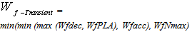 | (1) |
 | (2) |
2.2. Initial Gain Values
- In order to select the initial gain values for the four transient control loops, the tuning process is carried out as follows:
 The PLA loop gain (
 ) is firstly initialized to achieve a preliminary response time. In order to improve the engine response time,
  is then increased until the process begins to oscillate.In order to select the initial gain values for the four transient control loops, the tuning process is carried out as follows:
 In order to protect the engine against surge,
  is changed until the maximum rotor speed derivative (
 ) is limited to an allowable value. In order to select the initial gain values for the four transient control loops, the tuning process is carried out as follows:
 is changed until the minimum rotor speed derivative (
 ) is limited to an allowable value. Consequently, the engine is protected against flameout.In order to select the initial gain values for the four transient control loops, the tuning process is carried out as follows:
 In order to keep the engine integrity,
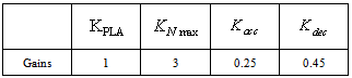
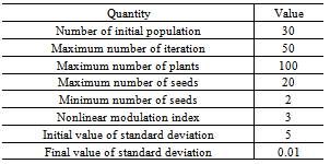
  is increased until the overspeed in every condition is vanished without overshoot. The initial values obtained by the above process for a case study in Seal Level Standard (SLS) condition is shown in Table.1.
|
2.3. Objective Function Formulation
- In this study, the objective function is formulated based on the engine response time and fuel consumption to illustrate the ability of the proposed approach to optimize short terms as well as long terms objectives. Also, the physical limitations are defined as penalty functions as follows:
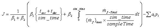 | (3) |
 . The term
  guarantees that the variation of cost function value remains between o-1 if
  . In the case that
  there is no need to add
  to the objective function. In this paper, the weight factors
 ,
,  are selected for the objective functions. It means that similar importance is considered for two objectives in the optimization process. In addition,
  and
and  are the acceleration and deceleration times which the engine requires to follow the PLA command (settling times with
  error). The Pi are penalty functions including over-speed, over-temperature and violation of
  during simulation (these penalty functions protect the engine from overshoots in speed and temperature as well as surge and flameout).
  are the penalty factors tuned in a trial and error manner to achieve the best results. Moreover, the design variables are the four transient control loop gains including
  ,
,  ,
,  and
and  as shown in Fig.1. Taking the nonlinear and switching nature of logical selection algorithm (1) into account, the IWO is proposed for Min-Max fuel controller gain tuning in this paper.
3. Application of IWO
- In this section, an overview of the IWO method is firstly presented. The method is then applied to the formulated optimization problem.
3.1. IWO Algorithm
- The IWO method flowchart is shown in Fig.2.a. As this figure illustrates, the method has 6 following steps:1- Initialization a population: a population of initial solutions is firstly dispread over the d dimensional problem space with random positions. In this study, the dimension of problem is four (
 ,
, ,
, and
and  ). 2- Fitness evaluation: each individual of population is evaluated in this step using defined objective function. 3- Reproduction: In this step, each member of the colony of weeds is allowed to produce seeds depending on its own and the colony’s lowest and highest fitness. 4- Spatial dispersal: after reproduction, the generated seeds are randomly spread over the search space according to normal distribution with a mean of zero, but varying standard deviation (SD). The variation of the SD with generation is defined as follow[13]:
 | (4) |
 is the maximum number of iterations and n is the nonlinear modulation index. The SD decreases from generation to generation. The decreasing rate depends on the value of the nonlinear modulation index which results in grouping fitter plants and eliminating the weaker plants[11]. Fig.2. b shows the variation of SD with generation for n=3.5- Competitive exclusion: After reaching the maximum number of plants, the competitor exclusion mechanism activates in order to eliminate the plants with poor fitness in the generation. This mechanism is formulated so that it gives a chance to plants with lower fitness to reproduce, and if their offspring has a good fitness in the colony, then, they will survive. 6- The above steps are repeated until the maximum number of iterations is reached[15].
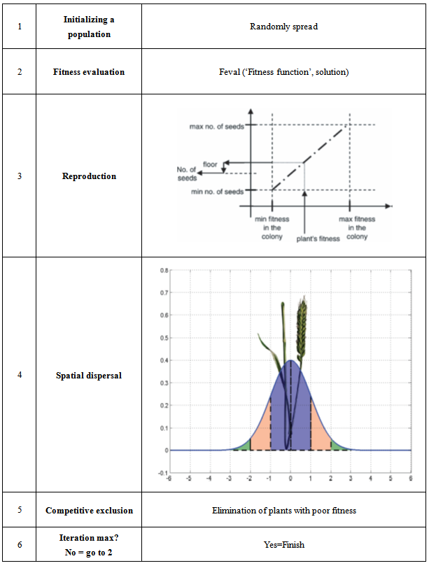 | Figure 2.a. IWO flowchart |
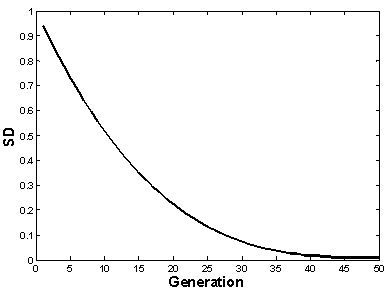 | Figure 2.b. variation of SD with generation in spatial dispersal step (n=3) |
3.2. IWO Results
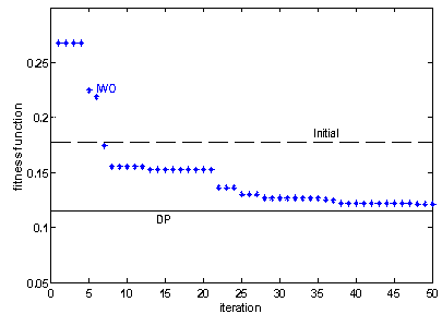 | Figure 3. The IWO optimization process history |
|
3.3. Comparison between IWO and Genetic Algorithm
- In order to show this fact that the IWO, as a newly developed optimization method, can be used as a good competitor for other well-established evolutionaryoptimization methods, the results obtained from this method are compared with the Genetic Algorithm (GA) results in this section. GA is a soft computing technique which can be used for optimization of the engineering problems. GA was introduced by Holland[2] as a probabilistic global search method based on the combination and generation of DNAs and Chromosomes that mimics the metaphor of natural biological evolution[17]. Table.3 compares the IWO and GA results. This table illustrates that the run time of GA is less than IWO run time. However, the IWO method has better convergence rate in comparison with GA method. In other words, the IWO method is more reliable for the problem with higher order discontinuity and talented for divergence. The cost function value for both methods is almost equal and close to global optimum obtained from DP method as shown in Table.3.
4. Effect of Optimization on the GTE Performance
- The IWO changes the GTE fuel controller loop gains and simulates the engine performance iteratively until the stopping criterion of the optimization problem is fulfilled. In order to verify the effectiveness of the proposed approach, the performance of the IWO optimized controller is tested for a defined pilot command. For this purpose, a computer simulation is developed for a single spool turbojet engine integrated with Min-Max fuel controller as a case study to evaluate the objective function values. The GTE model employed in this study is a Wiener model that its parameters are extracted from experimental tests. This model consists of a first order transfer function as a linear time invariant part and look-up-tables as nonlinear static part. The linear time invariant part simulates the lag of engine where the static nonlinear part gives details about the relationship between the fuel flow and the engine parameters such as rotor speed, compressor pressure ratio, exhaust gas temperature and exhaust thrust. More details about the engine modeling can be found in[18-20].The initial condition of simulation is GTE idle condition whereas a PLA command is applied to engine during 35 seconds as shown in Fig.4. The step input is selected to simulate the worse condition for the controller.
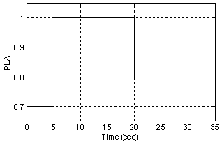 | Figure 4. Applied PLA for simulation |
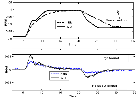
 ) are depicted in Fig.6. As shown in this figure, the optimized controller satisfies the engine overspeed limitation as well as the
  bounds. In other words, the optimization method protects the engine against physical limitation resulting in safe operation of the engine as well as nearly global optimal performance of the engine in time response and fuel consumption. Furthermore, Fig.6 shows that acceleration limiting loop at time t=7 sec is activated to protect the engine against surge. In other words, in IWO optimized controller, the PLA loop is firstly activated to achieve the best response time. The acceleration limiting loop is then activated at t=7sec when the
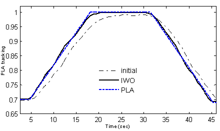
  reaches to the maximum allowable value. The designed controller is optimized with a step input PLA. To show this fact that the optimized controller is improved for other inputs, the simulation is run for another PLA. For this purpose, a slope based variation of PLA is applied to the engine and controller simulation and the results are presented in Fig.7. As shown in this figure, the optimized controller tracks the input PLA in a reasonable response time without any steady state error.Finally, it is worthwhile to mention that the IWO implementation is easier as the number of parameters is less for IWO in comparison with relatively old well-established evolutionary population-based methods like GA. Although the IWO method is slower than the GA method, it has higher convergence rate than GA. Therefore, the IWO is proposed as an appropriate candidate for gain tuning of GTE Min-Max fuel controller which is a nonlinear switching control system.
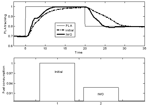 | Figure 5. Comparison of objective function terms in IWO and initial controller |
 | Figure 6. Physical limitation satisfaction using IWO |
 | Figure 7. Comparison of IWO optimized and initial controller for slope input PLA |
5. Conclusions
- In this paper, application of IWO technique for the GTE fuel controller gain tuning is presented. IWO as a newly developed method is applied to optimize a cost function consists of a long term objective i.e. fuel consumption, a short term objective i.e. response time and penalty functions in order to achieve an acceptable performance for the GTE and to protect the engine against physical limitations. The results illustrate that the IWO solution is reasonably close to the global optimum obtained from DP method. In addition, the simulation of GTE and optimized controller show that the IWO controller outperforms the initial controller in all objective function terms. The results confirm that in comparison with GA, the IWO runs slower but converges faster. Consequently, IWO can be successfully used for the optimization of the GTE Min-Max fuel controller parameters, resulting in an improved engine performance as well as the protection of the engine against physical limitations.
Nomenclature
References
| [1] | Kreiner. A, and Lietzau. K, “the use of onboard real-time models for jet engine control”, MTU Aero Engines, Germany. p. 27, (2002) |
| [2] | Holland, J, “Adaptation in natural and artificial system”, ed. M.U.o.M.P. Ann Arbor, (1975). |
| [3] | Shi. Y, Eberhart. R. C, “Empirical study of particle swarm optimization”, in Proc. IEEE International Conference on Evolutionary Computation., Washington, DC, pp. 1945–1950. July (1999). |
| [4] | Dorigo. M, “Optimization, Learning and Natural Algorithms”, PhD thesis, Politecnico di Milano, Italie,. (1992). |
| [5] | Zamani. M, Sadati. N, Karimi-Gh. M, “Design of an H∞ PID Controller Using Particle Swarm Optimization”. International Journal of Control, Automation, and Systems (2009). |
| [6] | Yousefi. M.R., Emami. S. A., Eshtehardiha. S, and Bayati Poudeh. M, “Particle Swarm Optimization and Genetic Algorithm to Optimizing the Pole Placement Controller on Cuk Converter”, in 2nd IEEE International Conference on Power and Energy (PECon 08), Johor Baharu, Malaysia. December 1-3,(2008). |
| [7] | Silva. V.V.R., Fleming. P.J., Sugimoto. J, and Yokoyama.R., “Multiobjective optimization using variable complexity modelling for control system design.” Applied Soft Computing, In Press, Corrected Proof, Available online 18 March (2007). |
| [8] | Sidhartha Panda. N, Padhy. P, “Comparison of Particle Swarm Optimization and Genetic Algorithm for TCSC-based Controller Design.” International Journal of Computer Science and Engineering, (2007). |
| [9] | Dambrosio. L, Sergio. M.M., Kamporeale. M, “performance of gas turbine power plants controlled by the multiagent scheme”. ASME, (2007). |
| [10] | Lin, C.O.W., “Comparison between PSO and GA for Parameters Optimization of PID Controller”, in Proceedings of the 2006 IEEE International Conference on Mechatronics and Automation, Luoyang, China, June 25 - 28 (2006). |
| [11] | Mehrabian, A.R. and Lucas. C, “A novel numerical optimization algorithm inspired from weed colonization”. Ecological Informatics, vol. 1, pp. 355–366. (2006). |
| [12] | Mallahzadeh. A.R, Oraizi. H, and Davoodi-Rad. Z, “Application of invasive weed optimization technique for antenna configurations” Progress In Electromagnetics Research, (2008). |
| [13] | Austin Spang. H, “Control of jet engines”. Control Engineering Practice, vol.7: p. 17. (1999) |
| [14] | Montazeri-Gh. M, Safari. A, “Tuning of fuzzy fuel controller for aero-engine thrust regulation and safety considerations using genetic algorithm”, Aerospace Science and Technology, Published by Elsevier Masson SAS (2010) |
| [15] | Sepehri Rad. H, and Lucos. C, “A Recommender System based on Invasive Weed Optimization Algorithm”, in 1-4244-1340-0/07-IEEE. (2007). |
| [16] | Dasgupta, S., Papadimitriou, C.H, Vazirani, U.V.,“Algorithms”. McGraw-Hill, Higher Education, available online, (2007). |
| [17] | Goldberg, D., “Genetic Algorithms in Search, Optimization and Machine Learning”, ed. Addison-Wesley. (1989). |
| [18] | Evans, C., “Testing and modeling aircraft gas turbines: an introduction and overview”, in UKACC International Conference on Cntrol. Conference Publication No. 455. (1998). |
| [19] | M. Montazeri-Gh and S. Jafari,: Evolutionary Optimization for Gain Tuning of Jet Engine Min- Max Fuel Controller, JOURNAL OF PROPULSION AND POWER, Vol. 27, No. 5, September–October (2011) |
| [20] | Kulikov, G.G. and Haydn Thompson. A, “Dynamic Modeling of Gas Turbines”. Industrial control center, Glasgow, scotland, U.K. (2003) |