-
Paper Information
- Next Paper
- Paper Submission
-
Journal Information
- About This Journal
- Editorial Board
- Current Issue
- Archive
- Author Guidelines
- Contact Us
International Journal of Aerospace Sciences
p-ISSN: 2169-8872 e-ISSN: 2169-8899
2013; 2(3): 124-137
doi:10.5923/j.aerospace.20130203.05
Design and Optimization of a Composite Vessel for Hydrogen Storage Subject to Internal Pressure and In-Flight Loads for UAVs
 Abstract
 Reference
 Full-Text PDF
 Full-text HTML
G. Romeo, F. Danzi, E. Cestino, F. Borello
Department of Mechanical and Aerospace Engineering, Politecnico di Torino Corso Duca degli Abruzzi 24, 10129 Torino Italy
Correspondence to: G. Romeo, Department of Mechanical and Aerospace Engineering, Politecnico di Torino Corso Duca degli Abruzzi 24, 10129 Torino Italy.
| Email: |  |
Copyright © 2012 Scientific & Academic Publishing. All Rights Reserved.
Research is being carried out with the aim of designinga Very-Long Endurance Solar Powered Autonomous Stratospheric UAV. This UAV could play the role of a pseudo satellite and could offer the advantage of allowing a more detailed land vision due to its relative closeness to land (17-20 km) at a much lower cost than a real satellite. Two different configurationsare under investigation in order to decide on the best solution that will completely satisfy the a priori imposed constraints. In recent years, the aeronautical community has increasingly focused on the design of solar powered platforms and zero emission airplanes; a coupled system (solar array and hydrogen fuel cells) can be used to supply energy throughout the entire day in order to ensure the continuous flight for several months. As known, a fuel cell system requires at least a couple of external tanks for fuel storage. Hydrogen and oxygen are stored using a pressure vessel installed inside the wing. In this way, the stored gases are subjected not only to pressure loads but also to in-flight loads that can abruptly change the optimum layout required to satisfy regulation requirements. A parametric analysis has been performed to define the optimum layout and the number of tanks necessary to supply the required power. In addition a genetic algorithm has been used to optimize the laminate layup in order to reduce the weight of the tank and ensure that it can resist without at failing catastrophically.
Keywords: FuelCell, Hydrogen Storage System, Pressure Vessel, Solar HALE-UAV, Optimization, Genetic Algorithm
Cite this paper: G. Romeo, F. Danzi, E. Cestino, F. Borello, Design and Optimization of a Composite Vessel for Hydrogen Storage Subject to Internal Pressure and In-Flight Loads for UAVs, International Journal of Aerospace Sciences, Vol. 2 No. 3, 2013, pp. 124-137. doi: 10.5923/j.aerospace.20130203.05.
Article Outline
1. Introduction
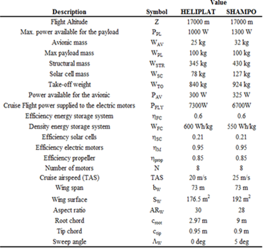
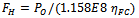
- UAV technology has advanced to such an extent that the aeronautical industry is now ready to expand into a new ‘added value’ Commercial industry. UAVs could be used in many applications ranging from border and costal patrol to homeland security, maritime surveillance, forest fire mapping, volcano eruption and many more. One of the great advantages of UAVs and, consequentially one of the most important reasons for their success, is the wide variety of operative characteristics of the vehicles; each mission can therefore be performed with a specifically designed machine. UAV related technology has reached a high level of maturity for some tasks, while other tasks that could be achieved by UAVs are far from being feasible because of the inherent complexity of the vehicles that could be deployed forthese purposes. These kinds of UAVs are still the subject of different research programmes.Research is currently being carried out,under the coordination of the first author,with the aim of designing a Very-Long Endurance Solar Powered Autonomous Stratospheric UAV (VESPAS-UAV)[1-11]; two different configurations (Fig. 1, Table 1) have been developed during the research programme.
|
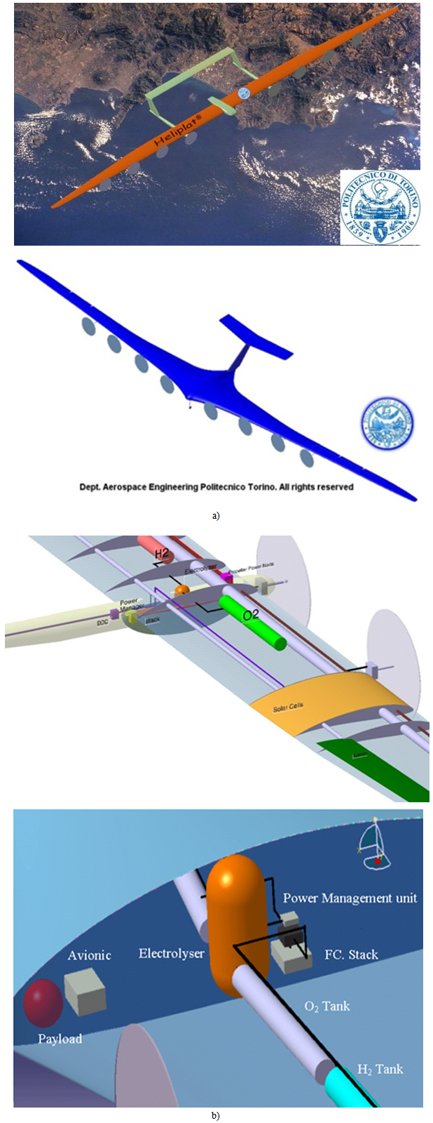 | Figure 1. a) The HeliPlat and the Shampo High Altitude Long Endurance Solar powered POLITO UAVs, b) 3D CAD model of the preliminary internal layout of both configurations |
2. General Sizing of the Hydrogen Tanks
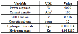
- The operational conditions of the tanks need to be evaluated taking into account some general constraints; since the tanks are positioned inside the wing, the main geometrical constraints are set on the basis of the wing profile (the external diameter must be less than the thickness of the wing) and feasibility (the length of the tank should not exceed 4 meters due to technological and manufacturing aspects). This constraint is particularly relevant for the HeliPlat configuration where the maximum wing thickness is 0.32m. Another important constraint concerns the electrolyser system; the optimal operational condition for this system is in fact the one in which hydrogen and oxygen are produced at a pressure of 100 bar. A pressure of 100 bar pressure was chosen as the operative pressure of the tanksin order to avoid additional equipment for weight, safety and reliability purposes.Only the internal pressure was considered for the general sizing. The inertial loads and loads due to bending and torsion of the wing were neglected. If these constraints are taken onto account, the mass of gas that needs to be stored has to be considered in order to define the overall dimensions of the tank. The hydrogen tank was chosen as the reference study casein this work; the oxygen tank (required in HALE applications because of the flight altitude) can be sized and analysed in a similar way.An estimate of the hydrogen mass requirement to supply power for night flight can be determinedthrough the following basic analysis, as in[13]. The voltage of an individual cell in a PEM fuel cell stack is given by:
 | (1) |
 | (2) |
 | (3) |
|
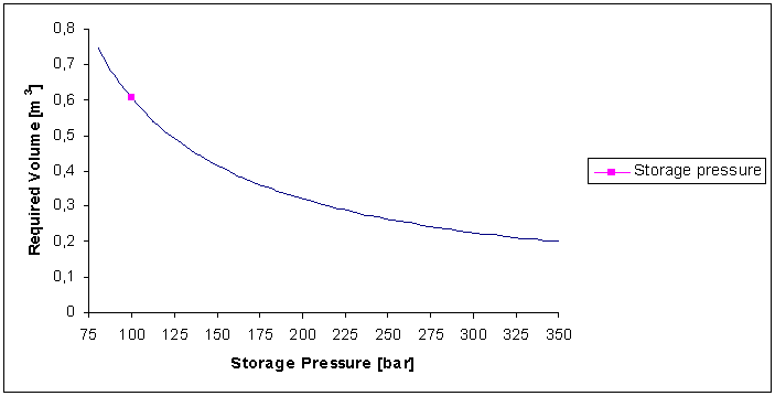 | Figure 2. Tank Volume vs.storage pressure |
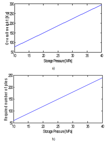 | Figure 3. a)Number of ply and b) overall weight variation vs storage pressure |
3. Progressive Ply Failure Analysis
- The burst pressure of the pressure vessel was evaluated in reference[14] by computing the first ply failure (FPF)of the laminate, while Tsai[15] suggested that the burst pressure should correspond to the last ply failure(LPF). However the FPF and LPF are coincident for the stacking of the same-orientationangle-ply laminate subjected to membrane loads. The layup obtained in this work shows a non-constant distribution of orientations, because inertial loads are taken into account and the laminate FPF and LPF could therefore be different. Both burst pressures definitionshave been compared in the present analysis.A Matlab® programme has been developedto carry outthe Progressive Ply FailureAnalysis. The Tsai Hill criterion[13] was chosen as the failure criterion. In the developed code, if a generic ply fails under the considered loads, the stiffness matrix is updated considering a degradation factor of zero, i.e. the lamina contribution to stiffness is neglected, regardless of the failure mode.The deformation induced by the previous loads has been taken into account in order to restore linearity between the applied loads and the failure index. The code continues iteratively until LPF is reached. A block diagram of the developed tool is shown in Figure 4. A series of composite laminates has been studied to validate the PPFA code and the results have been compared with both experimental and FE results. A composite laminate of T300/5208 graphite-epoxy with 24 layers andan S (S=a/h) of 150 was considered in Ref.[16]. The studied layuphas the following configuration: [θ4/04/-θ4]s. The laminate was subjected to uniaxial load Nx. The FE results in Ref.[16] were compared with Soni’s experimental data[17].The same set of laminates has also been studied with MSC Patran®/Nastran® using QUAD4 elements. The results obtained in[16],[17] and fromPatran®/Nastran® have been compared with the results obtained from the PPFA code.The value of tension shown in Figure 5 is a tension mean value which has been evaluated as follows:
 | (4) |
 | Figure 4. PPFA block diagram |
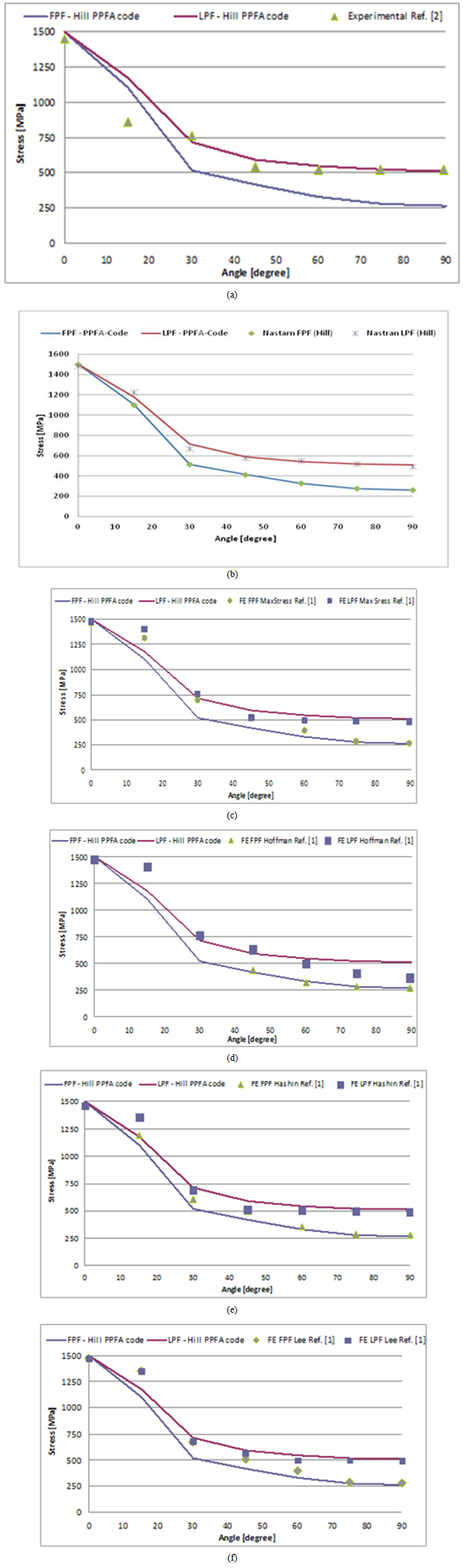 | Figure 5. Comparison of the stress results |
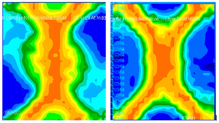 | Figure 6. Nastran SOL400 Fully Damaged panel a) the 30° case b) the 45° case |
4. Genetic Algorithm
- A GA[24] has been first developed to optimize the layup of a laminate subject to given mechanical, thermal and hygroscopic loads. The GA core is the MacroMec code, which was developed by the authors, using Matlab®, to evaluate stresses and strains in a given composite laminate. A block diagram of the GA is shown in Figure 7.
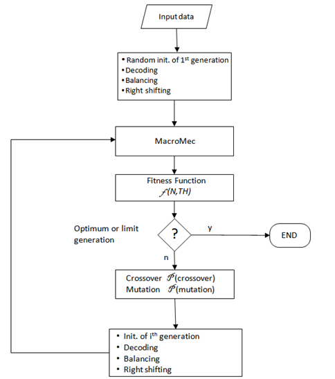 | Figure 7. Genetic Algorithm block diagram |
5. Pressure Vessel Optimization
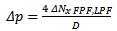
- The Pressure vessel (PV) optimization scheme is shown in Figure 8. Given a laminate layup, the algorithm computes the weight of the tank as the sum of the liner mass, ply mass, hydrogen mass and accessory package. The latter contribution, as indicated in[12], was estimated as 50% of the tank mass while the linear mass was evaluated as 10% of the tank mass. The inertial loads were evaluated by multiplying the whole mass by the ultimate load factor.From a technological point of view, since the vessel will be realized by tape winding, the laminate sequence must be the same for the whole tank and the design bending moment should be the maximum bending moment reached at the centreline.Furthermore, if the pressure vessel is considered as a pinned-pinned beam, the bending moment induces a membrane load:
 where σ was obtained using Hooke's law, ε being known
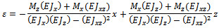 and where
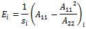 Once the inertial loads have been computed, the algorithm compares them with the inertial loads evaluated in the previous iteration. If they are different, the procedure first adds pressure loads and the genetic algorithm optimizes the layup with the new updated loads. Vice versa, if they are equal, the laminate layup cannot be improved and the algorithm updates the last computed strains given as the GA output. At this step, these strains are used to compute the corresponding state of stresses; these stresses, together with the PPFA code, are used to evaluate the safety margin of the tank. The PPFA, in fact, provides an evaluation of the ultimate load (FPF or LPF) and the pressure-generated stresses.The safety margin can be expressed in the PPFA, in terms of the difference between the applied pressure and the burst pressure (considering that the inertia-generated stresses are assumed as the starting stress status of the tank):
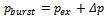 | (5) |
 | (6.1) |
 | (6.2) |
 | Figure 8. Pressure vessel Optimization scheme |
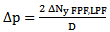
 | Figure 9. Tsai-Hill index distribution for the angle ply pressure vessel at different (+α/-α)12S orientations |
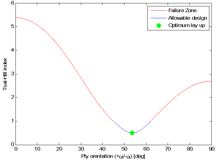
 | Figure 10. GA output plot of the implemented code |
6. Probabilistic Approachto the Pressure Vessel Composite Structure
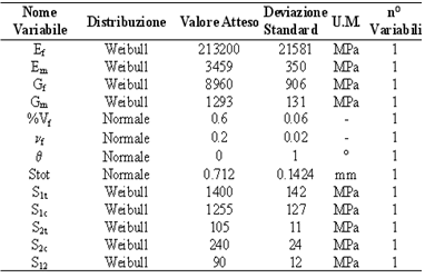
- The previously presented analysis was conducted to define the characteristics of the tank in order to focus on a specific configuration with respect to the performance index, regardless of which material is used to manufacture the tank. In the case of real applications, composite materials offer the possibility of improving the performance index manufacturing lightweight tanks. On the other hand, the safety/knockdown factors adopted for metals could be inadequate when innovative structural configurations and/or materials are considered. For example, if composite materials are adopted, traditional procedures lead to a “worst case” approach that is too penalizing to take into account their great dispersion and sensitivity to environmental conditions.Moreover, when safety/knockdown factors are used, no quantitative information is obtained on the safety or reliability level of the structures and it is thus almost impossible to evaluate the impact of different structural options on the safety and reliability or to have a constant level of criticality in each structural component. Both of these drawbacks lead to an increment in the weight of the structure without an equivalent or known increment in structural safety.A probabilistic approach is able to strengthen the understanding of the design process, since the designer has a measure of reliability and a safety level at his disposal during the process itself.A probabilistic preliminary design methodology for composite structures, in which the safety level is guaranteed by means of a quantitative measure, such as the nominal probability of failure, was developed in[18] and is here summarized and applied for the case of a composite filament-wound pressure vessel. The procedure can be described briefly through the following steps:1) Definition of a target probability of failure; definition of the initial structural configuration and description of the probabilistic interdependency of the structural components; definition of the sizing strategy; 2) evaluation of a first attempt “resistance effect” increment in order to meet the required probability of failure;3) sizing of the structure in order to achieve the resistance level evaluated in 2; 4) evaluation of the probability of failure of the new structural configuration: if this does not meet the target probability, a new loop is started from point 2 trough to point 4. Instead, if the target probability is met, a refinement of the structure is performed in order to check whether the configuration obtained in 3 presents the minimum possible number of layers that can guarantee the target probability.The model adopted for the pressure vessel is the one that was reported in[19]. The filament-wound pressure vessel is assumed to have adjacent ±θ angle layups that act as orthotropic units, as in Figure 11; the length of the vessel is considered large enough to consider the longitudinal bending due to the end closures as being limited to small portions of the tank itself, and longitudinal bending is therefore neglected.This case can be treated as a generalized plane stress problem. The adopted failure prediction criterion for a single layer of the orthotropic layer ± was the 3D quadratic one reported in[15] :
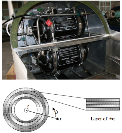 | Figure 11. Cylindrical pressure vessel scheme |
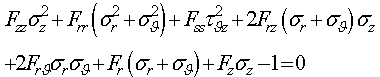 | (7) |
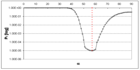 | Figure 12. Probability of failure of a 20 layer pressure vessel against the winding angle[20] |
|
7. Conclusions
- The optimization of a composite pressure vessel has been presented in the present work. From the general sizing of the hydrogen tank, it has emerged that the configuration that satisfies the whole set of requirements is the one in which two tanks are necessary to store hydrogen at a pressure of 100 bar. A progressive ply failure analysis code has been developed to compute the failure loads of a generic laminate subjected to mechanical loads. The PPFA code has been validated and it shows a good correlation between the experimental and the FE results. It has been shown that failure loads are necessary to calculate the burst pressure of the composite vessel and ensure fulfilment of regulation requirements. A genetic algorithm has been developed to optimize the layup of the composite vessel in order to save mass and reduce the influence of inertial loads. The optimized layup obtained from the GA runs was remarkably different from the case in which inertial loads were taken into account. The optimized stack sequence has in fact shown a notable presence of almost 0° plies in order to ensure an appropriate bending stiffness.An approach to the reliability based design of pressure vessels has also been presented in order to ensure a given probability of failure.
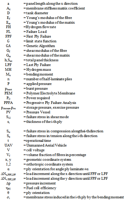
Nomenclature
References
| [1] | Romeo G.: "Design Proposal of High Altitude Very-Long Endurance Solar Powered Platform for Earth Observation and Telecommunication Applications". 48th Int. Astronautical Congress (IAF), October 6-10, 1997, Turin. Paper n. IAF-97-M.2.05. |
| [2] | Romeo G.: "Design of High Altitude Very-Long Endurance Solar-Powered Platform for Earth Observation and Telecommunication Applications".Journal Aerotecnica Missili e Spazio,Vol.77, N.3-4, July-Dec.98. pp. 88-99. |
| [3] | Romeo G., Frulla G., Cestino E., Corsino G.: "HELIPLAT: Design, Aerodynamic Structural Analysis of Long - Endurance Solar-Powered Stratospheric Platform”.AIAA Journal of Aircraft, Vol. 41, No. 6, Nov-Dic 2004, pp. 1505-1520. (ISSN: 0021-8669) |
| [4] | Romeo G., Frulla G.: "HELIPLAT: High Altitude Very-Long Endurance Solar Powered UAV for Telecommunication and Earth Observation Applications”.The Aeronautical Journal. Vol.108, N.1084, June 2004, pp. 277-293. (ISSN: 0001-9240) |
| [5] | Romeo G., Frulla G.: "HELIPLAT: Aerodynamic and Structural Analysis of HAVE Solar Powered Platform". 1st AIAA Technical Conference & Workshop on Unmanned Aerospace Vehicles, Systems, Technologies & Operations. Portsmouth, VA, USA, 20-23 May 2002. ISBN: 1-56347-565-0 |
| [6] | Romeo G., Frulla G., Fattore L.: “HELIPLAT: High Altitude Very-Long Endurance Solar Powered UAV for Telecommunication Applications. FEM Analysis, Manufacturing and Testing of 21m long CFRP Wing Box”.. Applied Vehicle Technology Panel Symposium on Unmanned Vehicles (UV) for Aerial, Ground and Naval Military Operations. Ankara (Turkey) Oct. 2000. RTO Meeting Proc.: MP-052, Paper N.12. |
| [7] | Romeo G.,Frulla G., Cestino E., Marzocca P.:” Non-linear Aeroelastic Behavior of Highly Flexible HALE Wings”. 25thInternational Congress of the Aeronautical Sciences (ICAS 2006), 3-8 September 2006, Hamburg, Germany, 11pages. ISBN: 0-9533991-7-6. |
| [8] | Tuzcu I., Marzocca P., Cestino E., Romeo G., Frulla G.,: ”Stability and Control of a High -Altitude-Long-Endurance UAV”, Journal of Guidance, Control, and Dynamics, Vol.30, No.3, May-June 2007, pp.713-721. (ISSN: 0731-5090) |
| [9] | Romeo G., Frulla G., Cestino E. “Design of high altitude long endurance solar powered unmanned air vehicle for multi-payload and operations”, Proc. of the Institution of Mechanical Engineers. Part G, Journal of Aerospace Engineering, Vol.221, 2007, pp.199-216. (ISSN: 0954-4100). DOI: 10.1243/09544100JAERO119. |
| [10] | Romeo G; Borello F: “Very-Long Endurance Solar Powered Autonomous Stratospheric UAV For Mediterranean Sea Border Surveillance, Forest Fire Monitoring, Fishery”. 33th International Symposium on Remote Sensing of Environment (33 ISRSE). JRC, Stresa, Italy, 4-9 May 2009. Paper n. 656. |
| [11] | Romeo G., Cestino E., Borello F., Pacino M.: “Very-Long Endurance Solar Powered Autonomous UAVS: Role and Constrants for GMES Applications”.28th Int. Conf. of the Aeronautical Sciences (ICAS 2012), Brisbane (Australia), 23-28 Sept. 2012. Paper ID294. |
| [12] | Romeo G., Borello F., Correa G.: “Set-Up and Test Flights of an All-Electric Aeroplane Powered by Fuel Cells”,AIAA Journal of Aircraft, 2011, Vol. 49, N.4 (July-Aug. 2011), pp.1331-1341. DOI: 10.2514/1.55329. |
| [13] | Colozza A. J., “Hydrogen Storage for Aircraft Applications Overview”, NASA/CR—211867, 2002 |
| [14] | W. Xiangyang, C. Jianqiao, “Robust optimum of laminated composite plates”, Acta Mechanics SolidaSinica, Vol 17, No. 4, December, 2004 |
| [15] | TsaiS.W.,”Composite design. Think Composites”, Dayton, Oh, 1988. |
| [16] | S. Tolson, N. Zabaras, “Finite element analysis of progressive failure in laminated composite plates”, Composite and Structure Vol. 38, No 3,pp. 361-376, 1991. |
| [17] | S.R. Soni, “A new look at commonly used failure theories in composite laminate”, 24th AIAA/ASME/AHS Structures, Structural Dynamics and Materials Conference, Procedures, pp.171-179, 1983 |
| [18] | Borello F., ”Approccio probabilistico al progetto di strutture aeronautiche in materiali compositi avanzati”. PhD. Thesis. Politecnico di Torino, 2008 |
| [19] | Lekhnitskii S.G.,“Theory of Elasticity of an anisotropic elastic body.”Holden-Day Inc: San Francisco, Ca, 1963. |
| [20] | G.Frulla, F. Borello, ”Structural reliability aspects for advanced composite material applications”. in Reliability Engineering Advances, Nova publisher 2009 ISBN 978-1-60692-329-0. |
| [21] | Frulla G; Cestino E.; Marzocca P, “Critical Behaviour of Slender Wing Configurations”. Proc. of the Institution of Mechanical Engineers. Part G, Journal of Aerospace Engineering, vol. 224, pp. 587-600 |
| [22] | Noll T.E. etal., "Investigation of the Helios Prototype Aircraft Mishap" Volume I - NASA Mishap report, Jan. 2004. |
| [23] | Romeo G., Frulla G., Cestino E., “Design of high-altitude long-endurance solar-powered unmanned air vehicle for multi-payload and operations”. In: Proceedings of The Institution Of Mechanical Engineers. Part G, Journal of Aerospace Engineering, vol. 221, pp. 199-216. |
| [24] | Mitchell M., “An introduction to Genetic Algorithm”, A Bradford Book, The MIT Press Cambridge, Massachusetts, London, England Fifth printing, 1999. |