Santosh Joteppa, Vinod S Chippalkatti
Centum Electronics Limited, 44, KHB Industrial Area, Yelahanka New town, Bangalore, India
Correspondence to: Santosh Joteppa, Centum Electronics Limited, 44, KHB Industrial Area, Yelahanka New town, Bangalore, India.
| Email: |  |
Copyright © 2012 Scientific & Academic Publishing. All Rights Reserved.
Abstract
Electronic packages like Hybrid Micro circuits (HMC’s) need to be Seam sealed in order to meet the hermeticity requirements for use in aerospace and defense application. These hermetically sealed packages need to be qualified by subjecting to various thermal and mechanical tests. Some of the tests call for qualification at higher vibration acceleration load and frequency of up to 2000Hz. If not taken care of such high acceleration and at high frequency range during design, seam sealed packages may lead to the fatigue cracks at sealed periphery. This paper describes the static method of designing and analyzing the package subjected to high vibration loads and without securing the package lid by any other methods. To understand the type of failure a detailed vibration testing for various acceleration loads and cross sectional thickness, analysis has been carried out on existing qualified packages to study the type of failure. Based on the results of failure mechanism a new lid has been designed and verified using the finite element analysis, by varying the flange thickness of the lid and increasing the acceleration level. Based on these results an optimum flange thickness has been selected, new lid manufactured, seam sealed and successfully qualified for higher vibration loads.
Keywords:
Vibration Load, Seam Sealing, FEA, Hermeticity, HMC
Cite this paper: Santosh Joteppa, Vinod S Chippalkatti, Design and Qualification of Hybrid Micro Circuit Packages for Higher Vibration Loads for Aerospace and Defense Application, International Journal of Aerospace Sciences, Vol. 2 No. 3, 2013, pp. 106-123. doi: 10.5923/j.aerospace.20130203.04.
1. Introduction
Hybrid Micro Circuits (HMC) are being widely used in the aerospace and defence industry for various applications to reduce the mass and volume. As Mass and volume have direct effect in the reduction of cost of satellite launch and missile electronic manufacturing. A Hybrid Micro Circuit (HMC) is a proven technology for the use in many aerospace and defence application in comparison with the discrete/PCB version in order to save mass and volume. These hybrid micro circuits are manufactured using thick film technology and need to be designed and qualified to meet various mechanical requirements in order to avoid mechanical and vibration failures during launch and transportation. The HMC packages need to be designed to meet the sealing requirements apart from meeting the vibration and thermal loads. In some of the subsystem for aerospace and defence application the packages need to be designed for a sine vibration load of more than 50g and to with stand such a high vibration loads the seam sealing area of the Lid through which the lid is welded to the package body need to be designed to meet the vibration load apart from meeting other requirements of thermal and mechanical design requirements.The HMC packages need to be designed to meet the following requirements as a minimum or in combination depending on the application, in defense and aerospace domain.1) Sine Vibration2) Random vibration3) Constant acceleration4) Shock load5) Thermal shock6) Temperature cycling7) Pressure of 45 PSI (Fine and Gross leak)One of the critical parts in the electronic packaging of HMC is the lid design which will be sealed to the package using seam sealing method to meet the hermeticity requirements. During the lid design following requirements need to be considered.● Minimum flange seal thickness for sealing to meet the sealing machine requirements based on the sealing machine capability● Minimum or no deformation during the pressure test to meet fine and gross leak requirements● Minimum or no deformation during mechanical vibration testing. ● Should restrict the movement by itself during the seam sealing ● To meet the Hermeticity requirementsFigure-1 shows the typical lid used for the sealing the package body. Sealing flange area shown in the figure-1 need to be finalized based on the requirements mentioned above.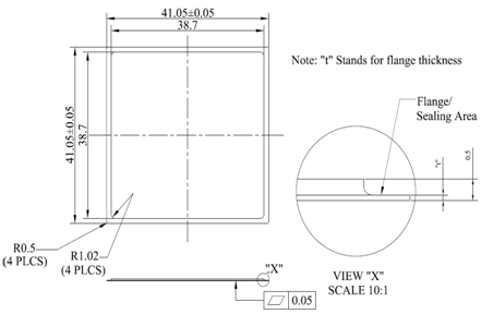 | Figure 1. Typical lid |
2. Background
To design the lid by considering requirements mentioned as above, for higher vibration “g” loads it is necessary to understand the failure mechanism at the sealing area. In order to understand the failures, a thorough study has been conducted using existing sealed package which was qualified to 20g vibration load and same has been briefed in the following section.
2.1. Existing Package Testing for Higher “g” Load
One of the existing HMC package which was designed for 20g vibration load has been selected for testing at higher vibration loads. The package has been subjected for vibration testing in steps of 30g, 40g and 50g acceleration load with 16 minutes duration in each of the axis and results have been studied in detail. The packages have been subjected for fine and gross leak test to check the hermeticity at the end of each step. After 30g vibration test the package has failed to meet the required seal leak requirements (better then 10-6) and to see the behavior, the same package has been subjected to 40g vibration load with 16 minutes duration in each of the axis and subjected to seal leak test and found huge change at sealed area. The package has been taken for visual inspection and found a hair line cracks all along the package sealing periphery i.e. near the edges of the package and away from all four corners of the package. In order to see the clear picture of these cracks at the sealed edges, the same package again subjected to 50g vibration testing and this time very clear hair line crack observed at sealing periphery and away from the corner of the package. Figure-2a and 2b shows the images of the hair line cracks under 40X magnification.It is understood from the above test that when the package is subjected for the higher vibration acceleration load the sealed area of the lid (to the package) will see the fatigue cracks. To further understand the mechanism of failure at this particular sealed area a cross section analysis of the package has been carried out by cutting one of the similar package and the detailed analysis is explained in the following section. Also it should be noted that the lid has not been secured by any other means during the vibration testing. 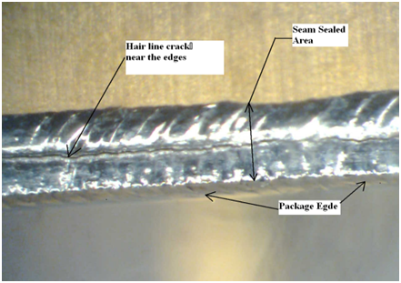 | Figure 2a. Cracks observed after vibration test |
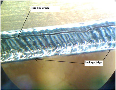 | Figure 2b. Cracks observed after vibration test in perpendicular to edge shown in Figure-2A |
2.2. Cross Section Analysis of Package
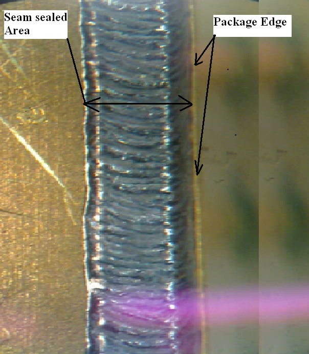
A detailed study has been carried out on the sealed packages to understand the thickness of the sealed area (flange thickness) after seam sealing. This thickness is required to find out the optimum flange thickness using static calculation method. The package has been cut in the center to study the approximate reduction in the thickness of flange at the sealing area. The thickness of the lid flange of this package before sealing was 5 mil. Figure-3 shows the package cross section with measured values of various cross section thicknesses. From this it clearly shows a reduction of 40% in the sealed area after seam sealing. The hair line fatigue cracks observed after vibration testing were in this area. It is also observed that fatigue crack line found during inspection are at the line where sudden change in thickness was taking place from 5 mil to 3 mil (as shown in Figure-3) after seam sealing. With this it was concluded that due to the sudden change in the thickness after sealing and subsequently subjecting for cyclic loading with higher acceleration load the seam sealed area away from the corner has seen the maximum cracks.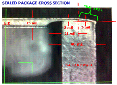 | Figure 3. Sealed package cross section |
With the required information obtained based on the above vibration testing by increasing the acceleration and cross section analysis a detailed design of the lid has been carried out by taking 50% reduction in thickness of the lid (i.e. thickness that will remain after seam sealing). The design is verified using finite element analysis and correlated with the results obtained with static method. The design and verification analysis are carried out for various flange thickness and by increasing the vibration “g” loads to get the optimum lid thickness to survive vibration load. It is also assumed that there is no other lid securing method has been used. Following paragraph explains the details of realization.
3. Realization
This section explains detailed design and analysis that have been carried out for various reduced flange thickness from its original thickness and by varying the vibration “g” loads to find out the optimum lid flange thickness. The thickness in design calculation considered is 50% of its original thickness to find the stresses at those location and Margin of Safety (MOS). same values of thickness have been used for finite element analysis to verify the design. The package parts, housing and lid have been designed using Kovar material and the construction is a typical one piece package body milled out from the Kovar block with four mounting lugs. The leads are isolated from the body using GTMS (glass to metal seals) technology.
3.1. Package and Lid Design
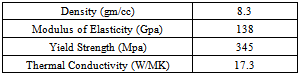
The package body size is decided based on the substrate size and wire bonding requirements. The material selected for the package body and Lid is Kovar (ASTM F-15) and the properties of Kovar material[1] are given in Table-1. Suitable glass material has been selected to match with the CTE of Kovar material for sealing the leads to the body.Table 1. Kovar Material Properties
 |
| |
|
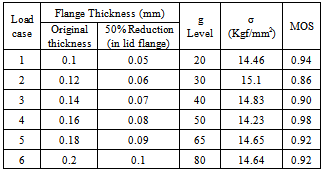
Following equation[2] is used for the calculation of stress under static condition by reducing the flange thickness of the lid. Based on the various iteration it was decided to increase the lid flange thickness and vibration acceleration load to arrive at a constant positive margin of safety. 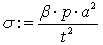 The results of various load cases are shown in Table-2. The MOS is calculated using a factor of safety (FOS) of 1.25 and Yield strength of Kovar material 345 MPa (35.15 Kgf/mm2). It can be seen from the Table-2 that a lid having 0.2mm flange thickness if reduced to 50% of its thickness during seam sealing, can withstand a sine vibration load of up to 80g. Finite Element Analysis approach has been used to verify the theoretically calculated results and understand the expected location of failure before actual manufacturing and testing of the lids and body.
3.2. Analysis
Due to involvement of huge cost and time for the manufacturing, assembly and testing of these lids along with other required parts it is necessary to verify the design. Finite element analysis (FEA) is carried out on the lid alone by assuming fixed boundary condition along all the four edges.Table 2. Calculated stress results with MOS
 |
| |
|
The results obtained from FEA are also helpful to verify maximum stress prone areas in the lid and to correlate to the cracks seen in physically tested lid after sealing the package. Analysis is carried out by taking same boundary conditions that are used for theoretical calculation.Figure-4 shows the finite element model of the lid alone with boundary condition applied and also it is assumed that there is no much contribution of loads from the package body and hence the package body is not considered for the finite element modeling.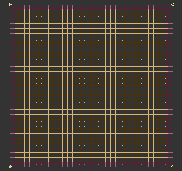 | Figure 4. Meshed model of Lid |
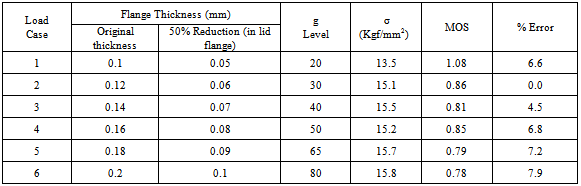
The finite element analysis is carried out by applying the vibration load in the form of gravity (Quasi static load) which can directly be input into the software. Figure-5 to figure-7 shows the analysis results for 20g, 50g and 65g. The results of other load cases are tabulated in Table-3. The results obtained from the FEA are correlated with that of theoretically calculated results and the % error has been calculated. Table-3 shows that the results are within the acceptable limits of 10%. The percent error further can be reduced by finer meshing of the model and due to the limited resources further iteration have not been carried out.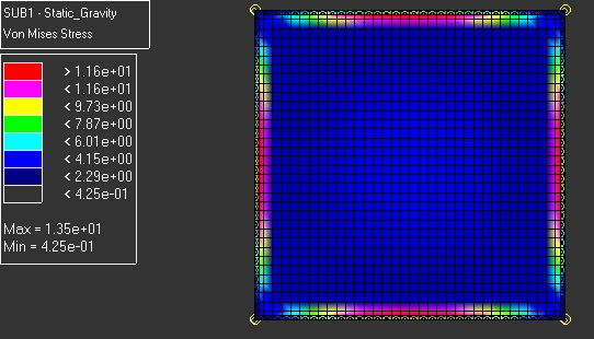 | Figure 5. Stress plot for 0.05 thick flange (reduced) and 20g acceleration |
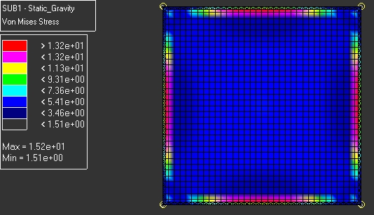 | Figure 6. Stress plot for 0.08mm thick flange (reduced) and 50g acceleration |
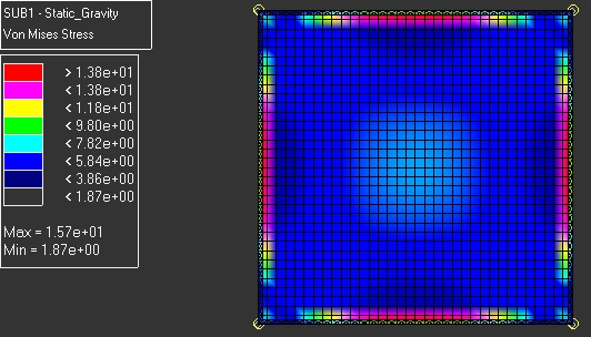 | Figure 7. Stress plot for 0.09mm thick flange (reduced) and 65g acceleration |
It is also found from the analysis results that the crack prone area near the edges on each side of the sealed lid which is similar to the cracks found during the physical testing of the product.Based on the results obtained from above design and analysis 0.2 mm thick, lid flange has been selected as it can withstand up to 80g acceleration load if reduced to 50% of its thickness i.e. 0.1mm and all other design parameter of lid not changed. The new lid and package body have been manufactured and subjected to seam sealing. After visual inspection the sealed package has been subjected to leak test, temperature cycling, and random vibration tests. By confirming the results of leak test the package has been taken to higher level vibration test and the results of same are discussed in the next section. Table 3. FEA Results with % error
 |
| |
|
3.3. Experimental Results
Validation of the product is carried out by subjecting the newly manufactured and seam sealed package to vibration testing and before higher level sine vibration testing the sealed package has been tested for Random vibration (18.1Grms, 2 minute duration) constant acceleration, Thermal shock and temperature cycling. A seal leak test is carried out before the test and at the end of sine vibration test. 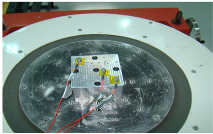 | Figure 8. Vibration fixture mounted on shaker |
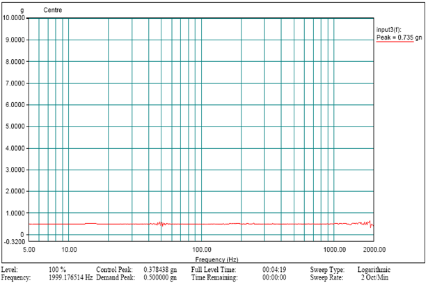
 | Figure 9. Fixture response at the center |
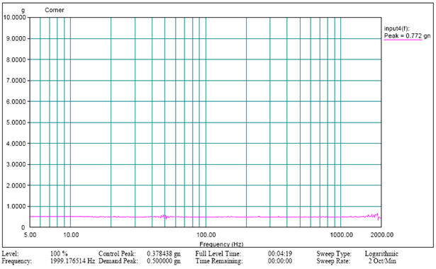
 | Figure 10. Fixture response at the corner |
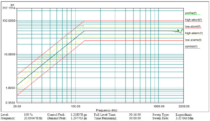
It is also an important factor to design and qualify the test fixtures used for the vibration[3],[4],[5] testing to avoid over testing and under testing of the packages. The fixture used for the testing has been validated (qualified) to avoid the resonances of the fixture in the test frequency range of 5 to 2000Hz before vibration testing of the actual package. The test fixture used for the testing is shown in figure-8, two accelerometers have been used for monitoring the responses, one at the center and one more at the corner of the fixture. The response of the two accelerometers in the graph (Refer Figure-9 and Figure-10) was found flat indicating that no resonance exists in the test range of 5 to 2000Hz. Figure-11 shows the vibration test setup for package with interface plate and qualified test fixture. The package is assembled to the interface plate using M2 stainless steel A2 grade screws and leads are secured as shown to avoid damage during the testing. One mini accelerometer is mounted on the lid using adhesive to characterize the response of the lid during the testing.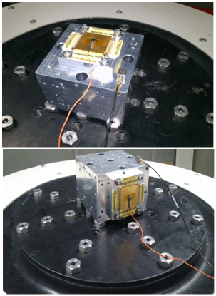 | Figure 11. Vibration test setup for Z axis and X/Y axes |
A low level sine sweep test is carried out from 5 to 2000Hz and first peak found at 1600Hz as shown in the figure-12. This test is carried out in a different lab due to non availability of small accelerometer for measuring the responses on the lid as the response will change if higher mass accelerometers when mounted on thin plate[6],[7], [8],[9]. After low level sine test the package has been subjected to 50g sine vibration test with 16 minutes duration in each of the axis and test plot of the same is given below. Due to similarity in the plots only one plot of Z axis vibration test is shown in Figure-13. After vibration in each of the axis the package has been visually checked to find any damage or cracks in the sealing area. The package also has been visually inspected under a magnification of 40X and no cracks and structural degradation found in any of the four edges of the sealed area. The package also subjected to gross and fine leak tests to check the leak rate and the leak rate obtained is of the order of 5.6x10⁻⁶.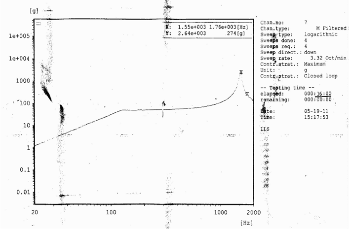 | Figure 12. plot of low level sine sweep test |
 | Figure 13. plot of 50g sine vibration test |
 | Figure 14. No cracks observed after 50g sine vibration test |
4. Conclusions
The above study is carried out by vibration testing in steps of increased acceleration level till 50g and cross sectional analysis of package to understand the percentage thickness reduction after seam sealing, has helped in understanding the overall failure mechanism and based on these test results, static method of design calculation is used to design the new lid for higher vibration load and subsequently the design is verified using the finite element analysis before manufacturing in order to save time and cost. This paper also show that the results helped in understanding that, the lid can be designed to withstand higher vibration loads much before manufacturing and testing using static method and can be verified by using any finite element analysis software before manufacturing of prototype. The results obtained by design and verification, have been proved by seam sealing the newly manufactured package body and lid and subjected the sealed package to higher acceleration vibration testing. Before testing the sealed package it also has go through the various other tests as indicated in section-1 and the lid has not been secured by any other means. The lid flange thickness is selected to suit the seam sealing capability of the machine (can be sealed with flange thickness of up to 0.25mm). The detailed experimental analysis of the cross section of the package contributed for the all the design and analysis of new lid to qualify for higher vibration acceleration load.
ACKNOWLEDGMENTS
The Authors would like to thank design, production and testing team for their contribution and efforts during the development and qualification of the package.
References
| [1] | Carpenter technical datasheet for Kovar Alloy. |
| [2] | Warren C. Young and Richard G. Udynas “Roark’s formulas for Stress and strain” McGraw-Hill Publishers, seventh edition, New Delhi. |
| [3] | Avitable P “Why you can’t ignore those vibration fixture resonances” Sound Vibration. No.3, 20-26. |
| [4] | Poncelet F “optimal design of fixture for vibration testing of structures on electro dynamic shaker” 12th Int. Congress on Sound & Vibration. |
| [5] | Scarton TD, Kimball DV and Tustin W “Vibration and test fixture design”. Tustin Institute of Technology, California. 12.1-12.6 |
| [6] | N. H. Baharin1 and R. A. Rahman “Effect of Accelerometer Mass on Thin Plate Vibration” Journal Mechanical (29). pp. 100-111. ISSN 0127-3396, 2010. |
| [7] | Døssing, O. Structural Testing Part 1 : Mechanical Mobility Measurement. Bruel and Kjaer. |
| [8] | Cakar. 0 and Sanliturk, K.Y. “Elimination of Transducer Mass Loading Effects from Frequency Response Functions” Mechanical System and Signal Processing, 19: 87-104. |
| [9] | Døssing, O. ‘Prediction of Transcducer Mass Loading Effects and Identification of Dynamic Mass’ Proceeding of the 9th IMAC, Schenectady NY, Union College. 306-311. |
 Abstract
 Reference
 Full-Text PDF
 Full-text HTML