J. E. Jam1, Aref A. Fard2
1Composite Materials and Technology Center, MUT, Tehran, Iran
2Mechanical Engineering Department, Ferdowsi University of Mashhad, Mashhad, Iran
Correspondence to: J. E. Jam, Composite Materials and Technology Center, MUT, Tehran, Iran.
| Email: |  |
Copyright © 2012 Scientific & Academic Publishing. All Rights Reserved.
Abstract
In the present study, vibratory behaviour of a robot arm with a single unit impact damper is investigated. To find the contact duration, oscillation of the impact mass and the main mass between and during the contacts is formulated. Using the contact duration and relative vibration of the masses, the restitution coefficient is obtained and employed to model the vibratory behaviour of the impact damper system. As a case study, effect of using the impact damper systems on application of a 3R robot is investigated. In this investigation, the third link of robot is considered laterally flexible with respect to other links. Effectiveness of using the impact dampers to suppress undesired vibration of robot arm is investigated with varying impact mass and gap size. Finally, the output force of the 3R robot tip with and without impact damper is compared. It is shown the impact damper can suppress undesired vibration of the robot arm and helps to improve application of the robot.
Keywords:
Impact Damper, Coefficient of Restitution, 3R Robot
Cite this paper: J. E. Jam, Aref A. Fard, Application of Single Unit Impact Dampers to Reduce Undesired Vibration of the 3R Robot Arms, International Journal of Aerospace Sciences, Vol. 2 No. 2, 2013, pp. 49-54. doi: 10.5923/j.aerospace.20130202.04.
1. Introduction
A single unit impact damper (or simply impact damper) is a lightweight auxiliary device, which consists of a container with a loose mass. The container has two barriers and it is connected to the main vibratory mass. In impact dampers, the loose mass (impact mass) absorbs kinetic energy of the main vibratory system (main mass) and converts it into heat through inelastic collisions between the secondary mass and the enclosure. This damper is effective for discrete and continuous systems in resonant operation and produces maximum displacement reduction during two impacts per cycle of motion[1-2]. Applications of the impact dampers to reduce excessive vibration of industrial machinery have been extensively investigated by researchers[3-7]. The reason for this interest lies in the following features of an impact damper:● Small and simple in construction.● Easy to mount on the main vibratory systems.● Effective application to suppress excess vibration.● No need to adjust parameters of an impact damper to the vibratory characteristics of the main vibratory systems.For suppressing vibrations, unlike viscose dampers, the impact dampers should not connect a non-vibrating mass. Furthermore, the impact dampers can dissipate undesired energy even in vacuum and other harsh environments.Therefore, such systems are useful in aerospace applications. In the past few years, behavior of impact dampers has been investigated experimentally, analytically and numerically [8-13]. Son et al.[14] proposed active momentum exchange impact dampers to suppress the first large peak value of the acceleration response due to a shock load. Bapat and Sankar[1] showed that the coefficient of restitution has a great effect on the performance of impact dampers. They demonstrated that in the case of single unit impact dampers, optimized parameters at resonance are not necessarily optimal at other frequencies. Cheng and Xu[6] obtained a relation between coefficient of restitution and impact damping ratio. They showed that optimal initial displacement is a monotonically increasing function of damping. Although the impact damper has been investigated for a long time, there are still several shortcomings in this area of research that should be noticed. The effect of impact dampers on better working of robot arm is one of the important aspects, which need to be further investigated. The main thrust of this paper lies in this subject. In doing so, in the present study, the governing equation of motion of a vibratory system, which is equipped with an impact damper, is formulated. The contact time (contact duration) is taken into consideration and it is achieved regarding to the formulation of the masses vibration. Using the calculated contact duration, the coefficient of restitution of the barriers is formulated.Finally, quenching undesired vibration of the robot arm tip with impact damper is investigated. For this reason, a 3R robot is modeled in SimMechanics toolbox of MATLAB software and it is equipped with a simple model of a single unit impact damper. The third link of robot is considered laterally flexible with respect to other links. The impact damper, which is constructed with spring, mass and viscous damper are connected to the third link tip. The output forces of robot with and without impact damper are compared and ability of the impact dampers to suppress undesired vibration of the robot arm is discussed.
2. Mathematical Modelling
2.1. Impact Damper
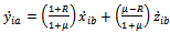
A simple model of a vibratory system, which is consist of an oscillator with linear stiffness K, mass M, viscous damping C and an impact damper with mass m and clearance d is considered. This system is schematically shown in figure (1). The impact mass motion within the main system can be divided to two separate motions:● First motion: motion of the impact mass between barriers (|y-x|<d/2).● Second motion: motion of the impact mass when it collides with the barriers (|y-x|≥d/2)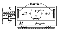 | Figure 1. Schematic of the single unit impact damper |
2.2. Motion of the Impact Mass between Barriers
Note that, in the present study, friction between the impact and the main masses is neglected because the gap size is assumed very small. Therefore, differential equations of the first motion for the main and impact masses are as follows: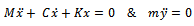 | (1) |
The above equation can be easily solved and motion of the primary mass between impacts i and i+1 can be written as follows: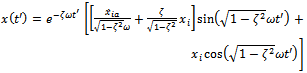 | (2) |
The subscript i represents the value of variables at the ith contact and parameters ω, ζ and t′ are defined as follows: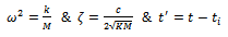 | (3) |
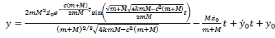
And motion of the impact mass can be formulated as follows  | (4) |
where the subscript ia and ib represent the value of variables at just after and just before of the ith contact, respectively. Velocities after ith contact are determined using the restitution coefficient and conservation of momentum. Therefore, the main mass and impact mass velocities after ith impact are as follows: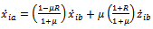 | (5) |
 | (6) |
Where µ is the mass ratio (µ =m/M) and R is the restitution coefficient.
2.3. Motion of the Impact Mass when it Collides with the Barriers
When contact occurs, the vibratory system can be shown using a two degree of freedom system. This system is shown in figure (2), schematically.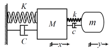 | Figure 2. Schematic while the impact mass colliding the primary mass |
Therefore, the governing equations of motion of the vibratory system should be written by two coupled equations which are shown in the following equations. | (7) |
 | (8) |
The above coupled equations can analytically be solved using and the main and impact mass displacements, when contact occurs, can be shown as follows[7]: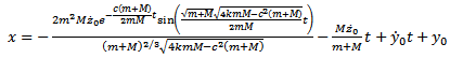 | (9) |
 | (10) |
where z=y‒x is the position of impact mass relative to the main mass. When the impact mass collides with the main mass, it stays in contact with the main mass for half the resonance period, which is usually called contact duration (tc). The contact duration is as follows: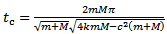 | (11) |
Substituting Eq.(11) into the relative velocity  relation, which is calculated using Eq.(9) and Eq.(10), a relation can be obtained for the restitution coefficient. Therefore, the restitution coefficient can be formulated as follows:
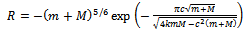 | (12) |
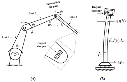 | Figure 3. Schematic of the 3R robot (A); Lateral deformation of the link 3 (B) |
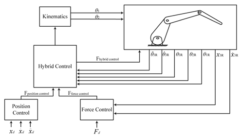 | Figure 4. The schematic block diagram of the 3R robot |
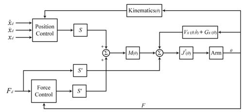 | Figure 5. The hybrid position/force controller block diagram |
3. Case Study
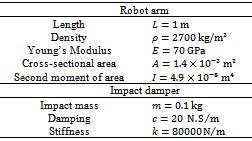
Effects of using the single unit impact dampers to suppress undesired vibration of structures are practical aspects in mechanics, which has not been fully investigated. In the present study, vibratory behavior of a serial robot, with and without impact damper is considered. The robot is equipped with a single unit impact damper, which is constructed using spring, mass and viscous damper. Figure (3-A) shows the presented robot, schematically. In the present study, the link 3 is considered laterally flexible with respect to other links. Lateral deflection of the link 3 is shown in figure (3-B). Dynamic properties of the link 3, which is shown in figure (4), are as K=3.0906EI/L3, M=0.25ρAL and C=2ζ(K.M)1/2. Note that ζ is the damping ratio and in the present study it is equal to 0.0004. properties of link 3 and the impact damper, which is connected to it is shown in Table (1). Table 1. Parameters for the robot arm (link 3) with an impact damper
 |
| |
|
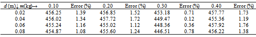
Using the tabulated data (table 1), the dynamic properties of the 3rd link are as follows: Substituting the impact damper properties and M into Eq. (12) results in R=0.715. A computer program was written, in MATLAB, to simulate equations (2) and (9) in real time. Consider the 3rd link of robot is fixed in its base (in other words w3=0 and dθ3/dt=0). The displacement response of link 3 (main mass) when it is subjected to the initial displacement x0=y0=-0.012m is shown in figure (3). In this figure great effect of using impact damper for suppressing undesired vibration is clearly shown.Figure 3 shows significant effect of using the impact damper for suppressing free vibration of the 3rd arm of robot when the other links are immobile. At here this question may be posed that: ″ when the other links are moving, what is the effect of using the impact damper on forced vibration of the 3rd link?″. To answer this question, the serial robot is modeled in SimMechanics toolbox of MATLAB and it is desired this robot apply constant force 450N at its wrist (as shown in figure 7-A). Variation of the output force, with and without impact damper is shown in figure (7-B). The tip force average, between 1 and 1.5 second, with the impact mass and the gap size is shown in Table (2). In this table, the tip foces are compared with 450N and the error is shown. The so-called parameter ′Error′ is defined as follows:
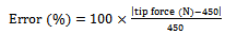 | (13) |
Variation of the Error with variables d and m are shown in figure (8). Note that, without impact damper the tip force average is equal to 466.67N, so the corresponding Error is equal to 3.7%. As shown in this figure, in two points (1) and (2) the parameters Error are respectively maximum and minimum.Force response of the robot tip without impact damper and with two impact dampers in the point 1 (d=0.040m and m=0.18m) and the point 2 (d=0.045m and m=0.30m) are shown in figure (9). As shown in this figure, the impact damper in poin2, works better than point1.Table 2. variation of the tip force average with varying the impact mass and gap size
 |
| |
|
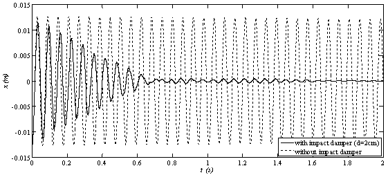 | Figure 6. Displacement response of the main mass without impact damper and with impact damper (d=0.01m) |
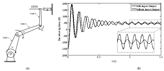 | Figure 7. 3R robot and the desired tip force (A); Force response of the robot tip without impact damper and with impact damper (d=0.04m, m=0.1kg) (B) |
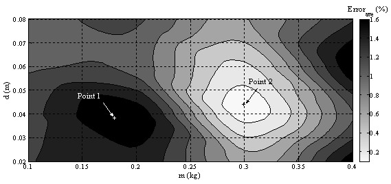 | Figure 8. Variation of the parameter error with d and m |
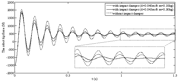 | Figure 9. Force response of the robot tip without impact damper and with two impact dampers |
4. Conclusions
In the present study, a practical and simple model of an impact damper is constructed using spring, mass and viscous damper. Formulation of the impact mass and the main mass vibrations are presented, between and during impacts. The important feature, which is carried out in the present analysis is that the deformation of the barriers is considered during the collision between the impact mass and the main mass. Therefore, the contact duration can be obtained and taken into consideration. This feature, which is really important for a resilient impact damper, helps us to find the coefficient of restitution. As a case study, the impact damper is used to suppress undesired vibration of a 3R robot arm. It is clearly shown that the such systems can effectively reduce undesired free vibrations. Moreover, effect of using the impact dampers for suppressing vibration of a robot tip is investigated. It is shown that improving the impact damper parameters can decrese the so-called Error more than 3.4%.
References
| [1] | Bapat, C.N. and S. Sankar, Single unit impact damper in free and forced vibration. Journal of Sound and Vibration, 1985. 99(1): p. 85-94. |
| [2] | Ibrahim, R.A., Vibro-impact dynamics : modeling, mapping and applications. Lecture notes in applied and computational mechanics,. 2009, Berlin: Springer Verlag. xi, 297 p. |
| [3] | Afsharfard, A. and A. Farshidianfar, Design of nonlinear impact dampers based on acoustic and damping behavior. International Journal of Mechanical Sciences, 2012. 65(1): p. 125-133. |
| [4] | Afsharfard, A. and A. Farshidianfar, An efficient method to solve the strongly coupled nonlinear differential equations of impact dampers. Archive of Applied Mechanics, 2012. 82(7): p. 977-984. |
| [5] | Guglielmino, E., Semi-active suspension control : improved vehicle ride and road friendliness. 2008, London: Springer. xvi, 294 p. |
| [6] | Cheng, J. and H. Xu, Inner mass impact damper for attenuating structure vibration. International Journal of Solids and Structures, 2006. 43(17): p. 5355-5369. |
| [7] | Cheng, C.C., Wang, J.Y., Free vibration analysis of a resilient impact damper. International Journal of Mechanical Sciences, 2003. 45(4): p. 589-604. |
| [8] | J.E.Jam and A. A.Fard, Investigating Vibratory Behavior of Nonlinear Single Unit Impact Dampers Using Perturbation Method and Genetic Algorithm. International Journal of Aerospace Sciences, 2012. 1(2): p. 4. |
| [9] | Zinjade, P.B. and A.K. Mallik, Impact damper for controlling friction-driven oscillations. Journal of Sound and Vibration, 2007. 306(1-2): p. 238-251. |
| [10] | Duncan, M.R., C.R. Wassgren, and C.M. Krousgrill, The damping performance of a single particle impact damper. Journal of Sound and Vibration, 2005. 286(1–2): p. 123-144. |
| [11] | Blazejczyk-Okolewska, B., Analysis of an impact damper of vibrations. Chaos, Solitons & Fractals, 2001. 12(11): p. 1983-1988. |
| [12] | Oledzki, A.A., Siwicki, I., Wisniewski, J., Impact dampers in application for tube, rod and rope structures. Mechanism & Mach. Theory, 1999. 34(2): p. 243-253. |
| [13] | Ema, S., Marui, E., Damping characteristics of an impact damper and its application. Int. J. Mach. Tools & Manuf., 1996. 36(3): p. 293-306. |
| [14] | Son, L., et al., Experiment of Shock Vibration Control Using Active Momentum Exchange Impact Damper. Journal of Vibration and Control, 2010. 16(1): p. 49-64. |
 Abstract
 Reference
 Full-Text PDF
 Full-text HTML