Inder Krishen Panditta
Mechanical Engineering Department, N. I. T. Srinagar, J&K, 190006, India
Correspondence to: Inder Krishen Panditta, Mechanical Engineering Department, N. I. T. Srinagar, J&K, 190006, India.
| Email: |  |
Copyright © 2012 Scientific & Academic Publishing. All Rights Reserved.
Abstract
In the design of aircraft frames buckling of spars, treated as columns, is to be taken into account. A new simplified and easy to use methodology for obtaining Euler critical loads of the columns is presented in this paper. It is based on concept of topological similarity used in the Principle of Quasi Work. This principle connects two topologically similar systems thereby leading to a unique concept of reference column. Critical load of columns with different boundary conditions is obtained by using a priory known equation of deflection of buckled reference column. This methodology is easy to use as critical load of columns are obtained by simple multiplications. It eliminates the use of bending moment expressions as well as solution of differential equations unlike conventional methods. The present methodology is successfully applied to columns with different boundary conditions in this paper.
Keywords:
Continuum Mechanics, Energy Methods, Structural Analysis, Column, Stability, PQW, TSS, TSC, TEC
Cite this paper: Inder Krishen Panditta, Euler Critical Load of Columns by Using Concept of Topological Similarity, International Journal of Aerospace Sciences, Vol. 2 No. 2, 2013, pp. 45-48. doi: 10.5923/j.aerospace.20130202.03.
1. Introduction
Aircraft frame being a honey comb structure is to be designed for buckling loads of columns (spars) and plates (covering the basic honeycomb structure). The spars are treated as columns with different boundary conditions. Here, in this paper a simple and easy to use method is developed for obtaining the buckling load of columns based on topological similarity. Concept of topologically similarity in the realm of structural mechanics was given by[1] while arriving at the Principle of Quasi Work (PQW). PQW is a very powerful pseudo energy principle which establishes a connection between Topologically Similar Systems (TSS). All the presently available structural analysis procedures e.g. finite element methods[2 - 5]; variational principles[6, 7] and energy methods[8, 9] are meant for a single structure and do not provide any connection between two structural systems. PQW thus fills existing void in the domain of structural mechanics. Using PQW, some useful theorems for discrete structural models were derived by[1, 10]. PQW was advantageously used by[11] for obtaining redundant reactions of beams. A quick and simplified method for obtaining nodal deflections of an indeterminate truss using PQW is presented by[12]. An easy methodology for obtaining deflections of structures without resorting to internal forces/ moments was given by[13]. PQW has much wider applicability as all the existing energy principles can be derived as special cases of PQW by restricting TSS to topologically identical systems i.e. when two systems are identical with each other in every respect. PQW utilizes known solution of a TSS to solve other determinate/ indeterminate topologically similar problems.Available methods for obtaining Euler buckling load of columns are based on the solution of differential equation involving internal bending moment distribution. Using PQW by restricting TSS to Topologically Equivalent Systems (TES)[1, 10–13] simplifies the solution process as it eliminates the need of writing bending moment expressions as well as solution of differential equations. For two TES, represented by subscripts ‘m’ and ‘n’, quasi strain energies Umn and Unm are equal. Hence, PQW can be used by equating quasi work expressions (i.e. Wmn = Wnm). Working with quasi work expressions is much easier compared to quasi strain energy expressions. Quasi work (Wmn) is calculated by multiplying applied loads acting on system ‘m’ with corresponding known deflections of TSS ‘n’. PQW involves two TSS out of which one of the systems (TSS1) will be used to represent the given determinate/ indeterminate problem at hand and other system (TSS2) with a priory known equation of its deflected elastic line is chosen by the user. Hence, a judicious choice of TSS2 leads to a unique reference column. Equation of the deflected elastic line of the reference column will be used to obtain critical loads of other given determinate/ indeterminate columns under different support conditions. As the reference column remains same it paves way for development of a general purpose interactive computer program for obtaining critical loads of other columns. In this paper, Euler stability criteria for long columns for different support conditions will be obtained by the application of PQW in the form W12 = W21 for which the given column and the reference column should be Topologically Equivalent Columns (TEC). Condition for two columns to be topologically similar / equivalent will be same as that for bending of beams derived in[11]. The condition for topological similarity for columns thus is that their depth in the plane of bending should be equal.In this paper, an attempt is made to define such a unique reference element whose solution for deflection/ deformation forms the basis for obtaining critical loads of other given problems. Few illustrative examples are also included. In these examples columns are shown horizontal and support reactions are taken positive in the upward direction and are denoted by R* (* denotes support A, B.…) while moment reactions from supports denoted by M* (* denotes support A, B,…) are taken positive in counter clockwise direction.
2. Topological Similarity
The concept of topological similarity germinated from the principle of quasi work. PQW was proved by[1] and subsequently stated by[10 - 13]. In PQW, quasi work (Wmn) done by self equilibrating set of external forces, ‘{P}m’, of one system ‘m’ (TSSm) while going through the corresponding set of compatible displacements, {d}n, of topologically similar system ‘n’ (TSSn) is equated to the quasi strain energy (Umn) due to the internal forces of TSSm, {F}m, while going through corresponding deformations, {δ}n, of TSSn. In mathematical terms it can be stated as: 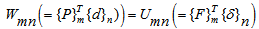 | (1) |
Where, Wmn is the quasi work, {P} is set of self equilibrating applied loads, {d} is set of corresponding deflections, {F} is the set of internal forces, {δ} is the corresponding deformation and ‘m’, ‘n’ represent the two topologically similar systems. Subscript of curly bracket denotes the system to which the expression inside the curly bracket refers to.From Eqn.(1) it is clear that external forces {P}should have their corresponding locations in other system. Hence, number of nodes in the two systems should correspond to each other. Moreover, number of members connected to nodes should be same or in other words nodal interconnectivity should also remain same. This is easily visualized in such structural systems where nodes and members are well defined like in Trusses. The principle even though derived for discrete structural systems can as well be applied to continuum structural systems by properly modifying Eqn.(1) for evaluating quasi strain energy and quasi work expressions. In what follows is an attempt to define reference column followed by few illustrative example.
3. Reference Column for Buckling
Reference Column for Buckling (RCB) is chosen as a column pinned at both ends ‘AB’ as shown in Fig. 1. The buckling load Pn = EI (nπ/L)2 for n=1 gives the critical load Pcr = π2EI/L2 for this column.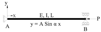 | Figure 1. Pinned Column: (RCB / TEC2) |
Its deflection curve is given by  | (2) |
Where α2 = P/EI, L is length of column, E is Young’s modulus of elasticity and I is second moment of cross sectional area. This solution is used to obtain the buckling loads for different support conditions by choosing this as Topologically Equivalent Column (TEC2) for which EI is taken to be equal to the column of the given problem.
4. Illustrative Examples
In this section, some of the problems related to columns solved in classical texts for Euler’s buckling load are chosen for illustrative purposes. Illustrations of columns with an additional intermediate support are also solved by present methodology. It can be observed that the present methodology neither needs expressions for internal bending moments nor any solution for differential equations, thus rendering the present methodology simple and easy.
4.1. Illustration 1: Fixed -Fixed Column
In this illustration critical load for a column ‘CD’ fixed at both the ends, shown in Fig.2, is obtained by using concept of topological similarity. The column parameters are E, I and L.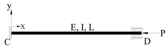 | Figure 2. Both ends fixed column. TEC1 |
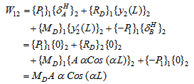
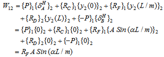
Quasi Work, W21 is calculated by taking the sum the product of set of self equilibrating forces (which includes applied forces as well as reactions from supports) acting on TEC2 (/RCB) with the corresponding deflections in TEC1 (/given problem) and W12 is calculated by taking the sum of the product of set of self equilibrating forces acting on TEC1 (given problem) with the corresponding deflections in TEC2 (RCB). These calculations are given below.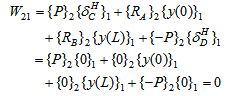 | (3) |
Similarly W12 is given by | (4) |
Where, is horizontal deflection at support ‘*’, R represents support reactions and M is moment reaction at supports.As MC = MD and W12 = W21. Eqn.(4) yields a non trivial solution given by: 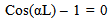 | (5) |
Eqn.(5) is satisfied for αL = 2nπ. This gives buckling load as Pn = 4 n2π2 EI / L2. Hence, critical load (n = 1) Pcr = 4 π2 EI / L2. This critical load is the same as is obtained by conventional methods. It is evident from this illustration that neither bending moment expression is needed nor a differential equation is to be solved for obtaining buckling load.
4.2. Illustration 2: Fixed -Free Column
In this illustration critical load of column ‘CD’ with parameters E, I and L, shown in Fig.3, is obtained by using the present methodology. The column is fixed at ‘D’ while end ‘C’ is unsupported.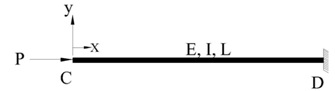 | Figure 3. Fixed – Free Column. TEC1 |
 | (6) |
As in illustration 1, W21 = 0 and by PQW, W12 = W21 (= 0). Eqn.(6), for a non trivial solution yields:  | (7) |
Eqn.(7) is satisfied for the values of αL = (2n +1) π/2. Thus buckling load Pn = (2n + 1)2π2 EI / 4L2. Hence, critical load (n = 1) is Pcr = π2 EI / 4L2. This value of critical load is same as is obtained by conventional methods.
4.3. Illustration 3: Pinned - Pinned Column with in - between Support
In this illustration stability criterion for the reference buckling column with an in-between support is obtained. The column ‘CFD’ as shown in Fig.4 is pinned at ends ‘C’ and ‘D’ and having another support at ‘F’ at a distance of x = L/m from left end.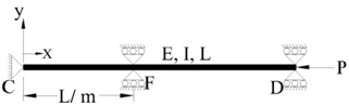 | Figure 4. Both ends Pinned with an intermediate support. TEC1 |
 | (8) |
As W12 = W21 (=0), Eqn.(8) yields a non trivial solution given by: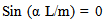 | (9) |
Above equation is satisfied if α L/m = nπ, with ‘n’ taking integer values. The buckling load for this column will then be Pn = EI α2 = n2 m2π2EI/L2. Critical load is obtained by putting n = 1 and is equal to Pcr = m2π2EI/L2 where ‘m’ takes integer values.It is not difficult to visualize that the critical load for different integer values of m (=1, 2, 3, ....) in above equation corresponds to the nth (1st , 2nd , 3rd ....) buckling load of the RBC(i.e. simply supported column) as support ‘F’ induces a node at the location L/m.
4.4. Illustration 4: Fixed -Fixed Column with in between Support
In this illustration critical load of the column of illustration 1 with an intermediate support will be obtained. As shown in Fig.5 another support is added to the column at ‘F’ at a distance of L/m units from the left end ‘C’. The calculations for critical load are shown below: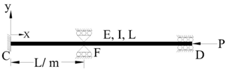 | Figure 5. Column with both ends fixed and an in between support |
Quasi work W12 is given by: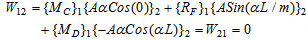 | (10) |
As MC = MD, Eqn.(10) reduces to | (11) |
Eqn.(11) is satisfied for αL/m = 2nπ, for integer values of ‘n’. This givess the following expression for buckling load | (12) |
Critical load for the column is obtained by substituting n = 1 in Eqn.(12) and is given by:  | (13) |
Here also the critical load for different values of m (=1, 2, 3, ....) in above equation yields nth (1st , 2nd , 3rd ....) buckling load of the fixed – fixed column as support ‘F’ induces a node at the location L/m.
5. Conclusions
1. Reference column for buckling (RCB) is successfully defined. 2. Equation of the deflected elastic line of RCB is successfully used to obtain the critical load of other columns with different boundary conditions. 3. Obtaining critical loads becomes simpler compared to the conventional methods if the present methodology is used. It is because one neither needs to have the knowledge of writing internal bending moment expressions for the beams nor needs to know the procedure for solving the differential equations.4. As solution of reference column (for deflection of its elastic line) can be used to solve all other column problems, it is possible to develop an interactive general purpose computer package for obtaining the critical loads of columns.
References
| [1] | Panditta, I.K., “Some Studies on Computer Aided Model Based Design”, Ph. D. Dissertation, IIT Bombay, India, 1996. |
| [2] | Akin, J.E., “Finite Elements for Analysis and Design”, Academic Press, London, 1994. |
| [3] | Cook, R.D., Malkus, D.J. and Plesha, M.E., “Concepts and Applications of Finite Element Analysis”, John Wiley & sons, New York, 1989. |
| [4] | Zienkiewicz, O. C. and Taylor, R. L., “The Finite Elements Method”, McGraw Hill Book Co., 1989. |
| [5] | Rao, S. S., “The Finite Element Method in Engineering”, Pergamon Press, 1989. |
| [6] | Reissner, E., “Formulations of Variational Theorems in Geometrically Non-linear Elasticity” Journal of Engineering Mechanics, Vol. 110, No. 9, 1984, pp 1377 – 1390. |
| [7] | Reissner, E., “On Mixed Variational Formulations in Finite Elasticity”, Acta Mech., Vo. 56, No. 3-4, 1985, pp 117-125. |
| [8] | Argyris, J. H. and Kelsey, S., “Energy Theorems and Structural Analysis”, Butterworth & Co. Ltd., 1960. |
| [9] | Shames, I.A. and Dym, C.L., “Energy and Finite Element methods in Structural Mechanics”, McGraw – Hill Book Co., 1985. |
| [10] | Panditta, I.K., Shimpi, R.P. and Prasad, K.S.R.K., “On the Theory of Discrete Model Analyses and Design”, International Journal of Solids and Structures, Vol. 36, 1999, pp 2443-2462. |
| [11] | Panditta, I.K., Ambardhar, R. and Dembi, N.J., “Redundant Reactions of Indeterminate Beams by Principle of Quasi Work”, AIAA journal, DOI: 10.2514/1.42470. |
| [12] | Inder Krishen Pandita, “Derivative Theorems of the Principle of Quasi Work”, International Journal of Aerospace Sciences, DOI: 10.5923/j.aerospace.20120103.02 |
| [13] | I. K. Pandita, M. Maruf Wani, “Deflection of structures using Principle of Quasi Work” ”, International Journal of Aerospace Sciences, DOI: 10.5923/j.aerospace.20120105.01. |
 Abstract
 Reference
 Full-Text PDF
 Full-text HTML