Marika Belardo, Modesto Pecora, Nicola Paletta
Aero-structural Design and Analysis Group - Aircraft Division, CIRA - Italian Aerospace Research Center, Capua, 81043, Italy
Correspondence to: Marika Belardo, Aero-structural Design and Analysis Group - Aircraft Division, CIRA - Italian Aerospace Research Center, Capua, 81043, Italy.
| Email: |  |
Copyright © 2012 Scientific & Academic Publishing. All Rights Reserved.
Abstract
The present paper is focused on techniques aimed at including a hydraulic servo-actuator model into the aero-elastic equation system. The test case is the elevator actuator of an EASA CS-25 business jet. The first step has been the servo-actuator dynamics modeling. A comparison between linear models (Taylor series and harmonic balance based) and the fully nonlinear model has been done in order to verify the linear approach. Differential equations governing the servo dynamics models are manipulated in order to obtain full 2nd order equation systems, by adding a “fictitious term”. This technique allowing for mass matrix inversion during aero-elastic response calculation has been chosen because it does not alter the servo dynamics behavior. The last step has been the inclusion of linear and nonlinear servo-actuator models in the aero-elastic system. The comparison between the linearized and nonlinear formulations is made in terms of aero-elastic behaviour and flutter speed.
Keywords:
Aero-elasticity, Hydraulic Servo-Actuator, Nonlinearity
Cite this paper: Marika Belardo, Modesto Pecora, Nicola Paletta, Aeroelastic Response with Non Linear Hydraulic Servo-Actuator Model, International Journal of Aerospace Sciences, Vol. 2 No. 2, 2013, pp. 37-44. doi: 10.5923/j.aerospace.20130202.02.
1. Introduction
The aim of this work lies in the need for reliable and quick tools during the aeroelastic certification process of small as well as large aircraft. Routine flutter analyses are carried out with the hypothesis of linearity. Displacements are small, aerodynamic forces are proportional to the response and the control system components respond linearly with the amplitudes. Nevertheless it is known that real systems are affected by nonlinearities, which might influence the aircraft aeroelastic behaviour. The most common sources of nonlinearities can be found both in the structure (e.g. engine supports, control surfaces) and in the aerodynamics (e.g. transonic regime). They can lead to some unwanted phenomena, such as limit cycle oscillations. Aeroelastic studies with structural nonlinearities -begun in the Fifties- can be divided into two methodological trends. The first studies made by Shen and Breitbach[1] -[6],[9], are based on linearization through harmonic balance. This approach later evolved by considering high order harmonics [8]. More recent studies are focused on alternative methods to solve nonlinear flutter[7]. Shen applied a simplified version of Kryloff and Bogoliuboff method, called “harmonic linearization” to solve nonlinear oscillations. The fundamental hypothesis is that the system must have a strong filteringproperty with respect to the higher order harmonics. This hypothesis is valid at flutter condition. In 1977 Breitbach[2] analysed various types of nonlinearities, focusing on lumped nonlinearities which are the most dangerous for flutter. Laterhe solved flutter of a sailplane affected by aileron and rudder nonlinearities by means of harmonic linearization approach[3]. An iterative technique, based on the updating of modal characteristics of the system, was set up in 1986 by Lee[4], but needed great computational effort in case of large systems. Other examples of the application of harmonic linearization were given by Luber[5], who performed nonlinear flutter calculation on Tornado aircraft, and Maričič[6]. Vio and Cooper[7] introduced a brand new approach, alternative to the harmonic linearization, to predict limit cycle oscillations. They simplified the nonlinear equations through a variable transformation and used a curve-fitting technique to approximate the non-linear stiffness behaviour as a polynomial. Other researchers considered higher order harmonics in the approximation[8], with the consequence of much more complication in the models especially when multiple nonlinearities are considered. Recent studies by Boeinghave again used the 1st order harmonic linearization, stressing its straightforward application when the system has strong filtering property (flutter condition)[9]. In 1991 Helmut Zimmermann[10] published the results of his work about inclusion of active hydraulic servo-actuators into flutter equation. One of the problems he faced with was finding a modal basis of the correspondent conservative system (i.e. without active actuators) obtained by means of suitable ground vibration tests. He modelled the system in State Space form, with Roger[11] approximation of the unsteady airloads. Also the present work is focused on techniques aimed at including a hydraulic servo-actuator model into the aero-elastic equation system. The dynamic sub-structuring approach has been used to model the rigid rotation of the control surface and the actuator terms, with considerable computational time saving. The paper is organized as follows. The first step has been the servo-actuator dynamics modelling. A comparison between linear models (Taylor series and harmonic balance based) and the fully nonlinear model has been done in order to verify the linear approach. Then differential equations governing the servo dynamics models have been suitably manipulated in order to allow for mass matrix inversion during aero-elastic response calculation. The last step has been the inclusion of linear and nonlinear servo-actuator models in the aero-elastic system. The comparison between the linearized and nonlinear formulations has been made in terms of aero-elastic behaviour and flutter speed.
2. Test Case
The test case is an EASA CS-25 business jetaircraft. Figure 1 depicts the aircraft plan-view.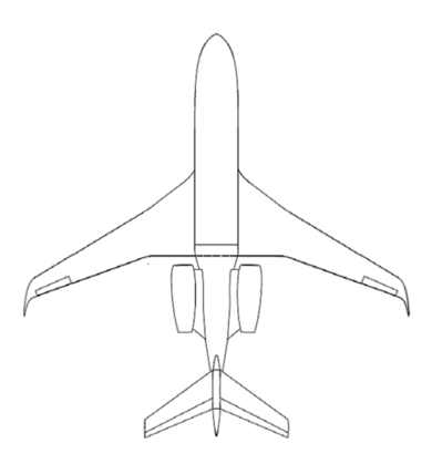 | Figure 1. Test case aircraft, plan-view |
The dynamic model of the aircraft is based on the global finite element model. The aerodynamic model is Doublet Lattice[12] whereas the matching model is made with superficial splines for lifting surfaces[13], mono- dimensional splines for control surfaces and rigid body for fuselage and nacelles.The control surface considered in the present study is the elevator, moved by means of a hydraulic servo-actuator. Without loss of generality the symmetric modal association is used to set up the methodology.
3. Dynamic Model of the Servo-actuator
The equations of the hydraulic servo-actuator are nonlinear in the valve flow term[14], Eqn. (1).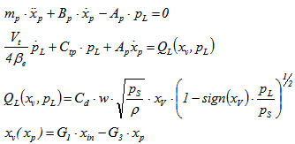 | (1) |
Where, Discharge coefficient
 Area gradient
 Oil density
 Supply pressure
 Pressure drop
  Valve spool displacement
 Piston displacement
 Valve flow
 Valve input
 External forces
 Total volume of cylinder chambers
 Piston mass
 Effective bulk modulus
  Piston area
 Viscous damping coefficient of piston
 Kinematic ratios Traditionally[14] the actuator equations are linearized by means of a 1st order Taylor approximation about the null operating point, Eqn. (2):
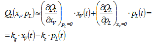 | (2) |
Where  and
and  are the so called “valve coefficients”.In this paper an alternative linearization is proposed. It is based on harmonic balance[15]. The valve coefficients are not calculated about the null operating point, but they depend on the nonlinear dynamic response of the system, hence on the oscillation amplitude. It is assumed a linear formulation for the valve flow and an error function is defined, Eqns. (3).
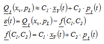 | (3) |
The vectorial notation is used to represent a set of values of the same variable at different time steps t in the time window T. The condition of minimization of the quadratic error gives the following system of equations in the unknowns C1 and C2, where T is the observation period, Eqn. (4). | (4) |
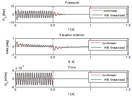
From Eqns. (4) it is clear that for the evaluation of the coefficients C1 and C2 one needs to solve the nonlinear dynamic servo-actuator time marching, and to calculate sets of coefficients with varying amplitudes of the sinusoidal input signal. One can then use these amplitude-varying coefficients to include the linearized servo model into the aero-elastic model of the aircraft. Even if a nonlinear time marching problem has to be solved, it is limited to the sole actuator, which is much smaller than the whole aircraft model, thus saving computational effort.The response of the servo-actuator to a sinusoidal servo-valve input is evaluated both for nonlinear and harmonic balance linearization, Figure 2. It shows that the nonlinear dynamic behavior is well approximated by harmonic balance linearization. | Figure 2. Servo-actuator dynamic response, comparison between nonlinear and harmonic balance linearized models |
It is apparent from Eqns. (1) that the dynamic model of the actuator, both for linear and for nonlinear case, is described by two 1st and 2nd order differential equations. Once these equations are added to the whole aero-elastic model a problem arises when mass matrix has to be inverted to calculate aero-elastic response, since it is singular. In order to overcome this problem a fictitious term in the second derivative of the pressure is added to the second of Eqns. (1). Care must be taken in the right choice of the coefficient of this term, because it has to be small enough not to alter the dynamic behaviour of the actuator but not too small to cause overflow. Since it multiplies a second order term it has been defined “fictitious mass  ”, as follows, Eqn. (5), where parameter k is used for tuning the coefficient, typical order of magnitude of k = 10-4.
 | (5) |
With the addition of the fictitious mass the following equations are obtained in State Space form for the actuator, Eqns. (6): | (6) |
 | Figure 3. Servo-actuator dynamic response, comparison between nonlinear 1st-2nd order and nonlinear 2nd-2nd order approaches (k = 10-4) |
 | Figure 4. Servo-actuator dynamic response, comparison between nonlinear 2nd- 2nd order and harmonic linearization 2nd-2nd order approaches |
To show consistency between the 1st-2nd order and 2nd-2nd order approaches, the actuator response to a sinusoidal servo-valve input is evaluated both for nonlinear case, Figure 3.Finally the nonlinear 2nd-2nd order is compared with the harmonic linearization 2nd-2nd order model, Figure 4. The input signal of the servo-valve is sinusoidal at 40 Hz, then it nullifies at 0.5 s, and has a duration of 4 s. The consistency between the models allows using both Harmonic balance linearization and fictitious mass approaches for the analysis of the whole aero-elastic system.
4. Linear Flutter Analyses
The present Chapter shows the results of flutter analyses carried out in the frequency domain and in the time domain by including 2nd-2nd order model of servo-actuator. Both Taylor and Harmonic balance linearization are compared. Unsteady aerodynamic forces have been modelled with Roger approximation[11]. The whole aero-elastic model uses the dynamic sub-structuring to model elevator control surface and the additional degrees of freedom of the servo-actuator.
4.1. Frequency Domain
The analyses in the frequency are carried out with PK continuation method.Also with flutter analyses both linearization methods are equivalent as regards flutter speeds and flutter modes. The flutter occurs at a speed equal to  , where
  is the design diving speed. Figure 5 and Figure 6 show the v-g plots obtained with Taylor linearization and Harmonic balance linearization respectively. Flutter instability involves the wing.
| Table 1. Flutter speed, results |
| | | VF/VD | fF[Hz] | | Harmonic Balance linearization | 1.631 | 8.253 | | Taylor linearization | 1.630 | 8.254 |
|
|
4.2. Time Domain
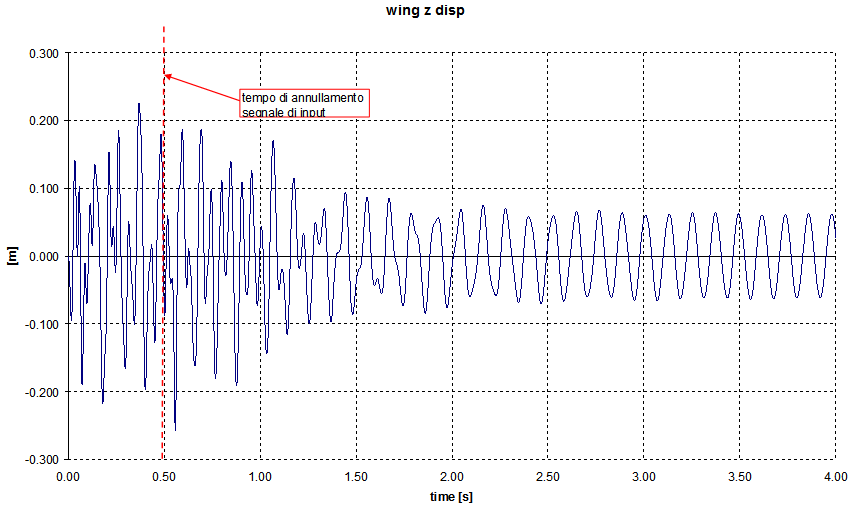
The aero-elastic response has been evaluated at a speed near flutter by exciting the servo-valve with the same input signal used to obtain the results shown in Figure 4. The 2nd-2nd order model of Harmonic balance linearized servo-actuator has been used. Calculation performed below the expected flutter speed showed no instability. The wing tip displacement at flutter condition is shown in Figure 7.Again the persistent oscillation at flutter speed confirms the results obtained in Figure 6. 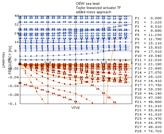 | Figure 5. Flutter analysis results, 2nd-2nd order servo model, Taylor linearization |
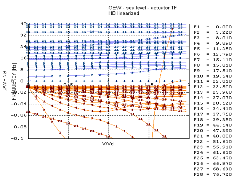 | Figure 6. Flutter analysis results, 2nd-2nd order servo model, Harmonic balance linearization |
 | Figure 7. Wing displacement at flutter condition |
5. Nonlinear Flutter Analysis
The full nonlinear aero-elastic model in State Space form has been formulated and implemented in MATLAB®code. The system has been solved time marching with 4th order Runge-Kutta method. The input signal of the servo-valve is the same used to obtain the results shown in Figure 4 and Figure 7. Unsteady aerodynamic forces have been modelled with Roger approximation[11]. The whole aero-elastic model uses the dynamic sub-structuring to model elevator control surface and the additional degrees of freedom of the servo-actuator. The servo-actuator model is obtained with the “fictitious mass” approach (2nd-2nd order nonlinear differential equations). The aero-elastic system in synthetic form is given by Eqn. (7).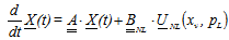 | (7) |
Where: 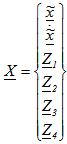 State vector
 Aerodynamic states (Roger)
 Elastic modes, rotation of elevator, actuator pressure
 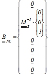 Nonlinear control matrix
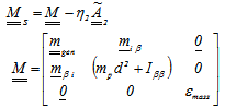 Mass matrix,
  is the corrective term due to Roger rationalization
 Nonlinear forceThe results of nonlinear aero-elastic response analysis, carried out near flutter speed show again that
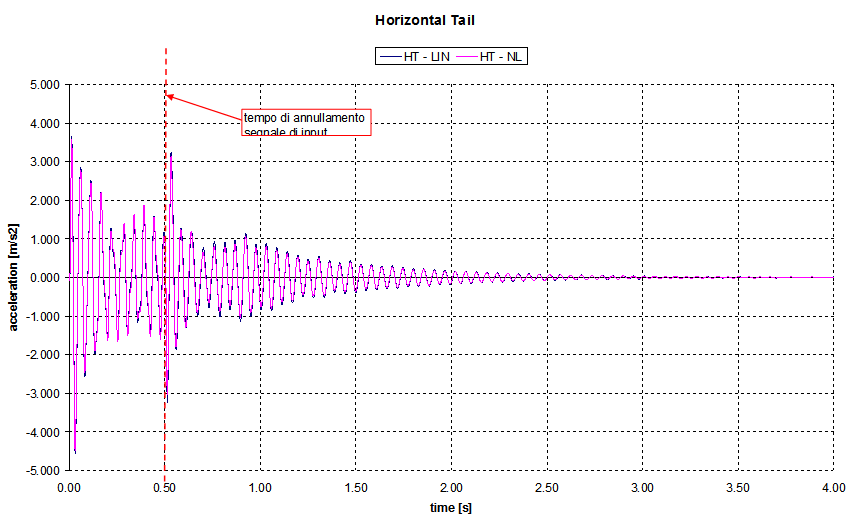
  . This is due to the fact that this type of nonlinearity for this particular test case does not affect flutter. The accelerations picked at wing tip and horizontal tail are compared with linear model, Figure 8 and Figure 9.
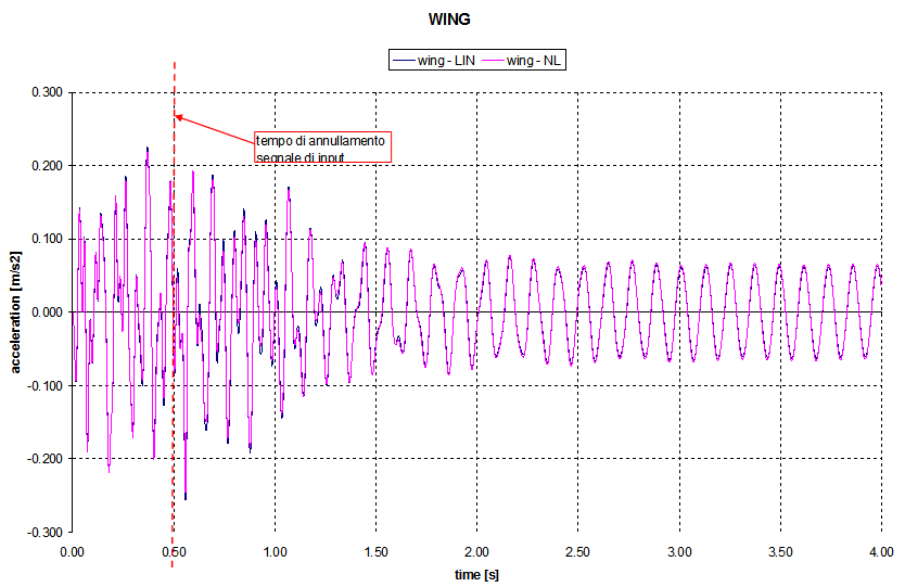 | Figure 8. Wing acceleration: Linear vs Nonlinearaero-elastic model |
 | Figure 9. Horizontal tail acceleration: Linear vs Nonlinearaero-elastic model |
6. Conclusions
In this work techniques aimed at including a hydraulic servo-actuator model into anaircraft aero-elastic system have been developed. Different linear dynamic models of the servo-actuator were tested and compared with respect to full nonlinear model.To allow for the inclusion of the actuator dynamic model into the aero-elastic model a suitable manipulation of the equations was operated by means of a “fictitious mass”. It has been verified that harmonic balance linearization with fictitious mass approach are a good and relatively effortless approximation to insert actuator into aero-elastic model. Finally a full nonlinear aero-elastic model (nonlinearity in the actuator) with the fictitious mass approach was set up. Results show consistency among the different proposedapproaches in terms of aero-elastic behaviour and flutter speed.
ACKNOWLEDGEMENTS
This work was developed within a PhD dissertation. The authors would like to thank Prof. Leonardo Lecce of Università degli Studi di Napoli Federico II for his precious advices and Eng. Antonio Sollo of Piaggio Aero Industries for all the aircraft data.
References
| [1] | S. Shen, “An Approximate Analysis of Nonlinear Flutter Problems”, Journal of the Aerospace Sciences, vol. 26, no. 1, pp. 25-31, 1959. |
| [2] | E. J. Breitbach, “Effect of Structural Nonlinearities on Aircraft Vibration and Flutter”, AGARD, TR 665, 1977. |
| [3] | E. J. Breitbach, “Flutter Analysis of an Airplane with Multiple Structural Nonlinearities in the Control System”, NASA Tech. Pap. 1620, 1980. |
| [4] | C. L. Lee, “An Iterative Procedure for Nonlinear Flutter Analysis”, AIAA Journal, vol. 24, no. 5, pp. 833–840, 1986. |
| [5] | W. G. Luber, “Flutter prediction on a combat aircraft involving backlash and actuator failures on control surfaces”, in Proceedings of Int. Forum on Aeroelasticity and Structural Dynamics, 1995. |
| [6] | N. Maričič, “Influence of Structural Backlash and friction in command system on the aircraft flutter”, Theoret. Appl. Mech., vol. 31, no. 3-4, pp. 317-344, 2004. |
| [7] | G. A. Vio, J. E. Cooper, “Lymit Cycle Oscillation Prediction for Aeroelastic Systems with Bilinear Stiffness”, Int. J. of Appl. Math. and Mech., Vol. 3, pp. 100-119, 2005. |
| [8] | L. Liu, E. H. Dowell, “Harmonic balance approach for an airfoil with a freeplay control surface”, AIAA Journal, vol. 43, no. 4, pp. 802-815, 2005. |
| [9] | J. Gordon, E. Meyer, R. Minogue, “Nonlinear Stability Analysis of Control Surface Flutter with Free-Play Effects”, Journal of Aircraft, vol. 45, no. 6, pp. 1904-1916, 2008. |
| [10] | H. Zimmermann, “Aeroservoelasticity”, Computer Methods in Applied Mechanics and Engineering, vol. 90, pp. 719-735, 1991. |
| [11] | K. L. Roger, “Airplane Math Modeling and Active Aeroelastic Control Design,” AGARD CP-228, pp. 1–11, 1977. |
| [12] | E. Albano, W. P. Rodden, “Doublet-Lattice Method for Calculating Lift Distributions on Oscillating Surfaces in Subsonic Flows,” AIAA Journal, vol. 7, no. 2, pp. 279-285, 1969 |
| [13] | R. L. Harder, R. N. Desmarais, “Interpolation Using Surface Splines”, Journal of Aircraft, vol. 9, pp. 189-191, 1972. |
| [14] | H. E. Merritt, “Hydraulic Control Systems”, John Wiley & Sons Inc., 1967. |
| [15] | P. Hagedorn, “Non-linear Oscillations”, Oxford Science Publications, 1988. |
 Abstract
 Reference
 Full-Text PDF
 Full-text HTML