Alexander Bolonkin
C&R, Consulting and Research Co., 1310 Avenue R, Suit 6-F, Brooklyn, NY, 11229, USA
Correspondence to: Alexander Bolonkin, C&R, Consulting and Research Co., 1310 Avenue R, Suit 6-F, Brooklyn, NY, 11229, USA.
| Email: |  |
Copyright © 2012 Scientific & Academic Publishing. All Rights Reserved.
Abstract
This picks up on the author’s early work of increasing range of the shells and bullets 2 – 5 times by including in its design small wings[1]-[4]. The shell/bullet specially formed wings support the projectile in the air, does not allow it to fall in earth’s surface as the kinetic energy the projectile is not spent fighting the forces of gravity and air resistance. This is an important innovation as it can be used in conventional rifles and gun with rifled barrel and rotary shell/bullet. The second idea is radical change of trajectory. The projectile reaches high altitude and glides from height using wings with subsonic speed and a good ratio lift/drag. Author developed theory of these projectile and computed some projects which show high efficiency of these innovations (by computer simulation). This can be immediately integrated into the arms industry and army because it does not require new weapons (rifles, guns), but is a modification only of the bullets and shells.
Keywords:
Wing Projectile, Wing Shell, Long Distance Shell, Long Distance Bullet
Cite this paper: Alexander Bolonkin, Long Distance Bullets and Shells, International Journal of Aerospace Sciences, Vol. 2 No. 2, 2013, pp. 29-36. doi: 10.5923/j.aerospace.20130202.01.
1. Introduction
History. The idea of a wing artillery shell was first published in 1972[1]–[2] with the full theory published in[3]-[7].General info. Muzzle velocity is the speed a projectile has at the moment it leaves the muzzle of the gun. Muzzle velocities range from approximately 400 ft/s (120 m/s) to 1,200 ft/s (360 m/s) in black powder muskets, to more than 4,000 ft/s (1,200 m/s) in modern rifles with high-performance cartridges such as the .220 Swift and .204 Ruger, all the way to 5,700 ft/s (1,710 m/s) for tank guns firing kinetic energy penetrator ammunition. The velocity of a projectile is highest at the muzzle and drops off steadily because of air resistance.A shell is a payload-carrying projectile which, as opposed to shot, contains an explosive or other filling, though modern usage sometimes includes large solid projectiles properly termed shot (AP, APCR, APCNR, APDS, APFSDS and proof shot). Shells usually have the shape of a cylinder topped by an ogive-shaped nose for good aerodynamic performance, possibly with a tapering base; but some specialized types are quite different.Shells are usually large caliber projectiles fired by artillery and combat vehicles (including tanks), and warships. The largest shells ever fired were those from the German super-railway guns, Gustav and Dora, which were 800 mm (31.5") in calibre[17]. Very large shells have been replaced by rockets, guided missile, and bombs, and today the largest shells in common use are 155 mm (6.1"). The weight of shells increases by and large with caliber. A typical 150 mm(5.9") shell weighs about 50 kg, a common 203 mm (8") shell about 100 kg, a concrete demolition 203 mm (8") shell 146 kg, a 280 mm (11") battleship shell about 300 kg, and a 460 mm (18") battleship shell over 1500 kg. The Schwerer Gustav supergun fires 4.8 and 7.1 tonne shells.US scientists with a full-scale cut-away model of the W48 155-millimeter nuclear artillery shell, a very small tactical nuclear weapon with an explosive yield equivalent to 72 tons of TNT (0.072 kiloton), demonstrated that it could be fired from any standard 155 mm (6.1 inch) howitzer e.g. the M114 or M198.Amour-piercing discarding sabot. Tanks have a strong amour which commonly uses tungsten shell for increasing armor-presiding. However, tungsten is very dense, and tungsten rounds of full-caliber design are too massive to be accelerated to an efficient velocity for maximized kinetic energy. This is overcome by using a reduced-diameter tungsten shot, surrounded by a lightweight outer carrier, the sabot. This combination allows the firing of a smaller diameter (thus lower mass/aerodynamic resistance/ penetration resistance) projectile with a larger area of expanding-propellant "push", thus a greater propelling force/acceleration/resulting kinetic energy.Once outside the barrel, the sabot is stripped off by a combination of centrifugal force and aerodynamic force, giving the shot low drag in flight. For a given caliber the use of APDS ammunition can effectively double the anti-tank performance of a gun.An Armor-Piercing, Fin-Stabilized, Discarding Sabot (APFSDS) projectile uses the sabot principle with fin (drag) stabilization. A long, thin sub-projectile has increased sectional density and thus penetration potential. However, once a projectile has a length-to-diameter ratio greater than 10 (less for higher density projectiles), spin stabilization becomes ineffective. Instead, drag stabilization is used, by means of fins attached to the base of the sub-projectile, making it look like a large metal arrow.HEAT shells are a type of shaped charge used to defeat armored vehicles. They are extremely efficient at defeating plain steel armor but less so against later composite and reactive armor. The effectiveness of the shell is independent of its velocity, and hence the range: it is as effective at 1000 meters as at 100 meters. The speed can even be zero in the case where a soldier simply places a magnetic mine onto a tank's armor plate. A HEAT charge is most effective when detonated at a certain, optimal, distance in front of the target and HEAT shells are usually distinguished by a long, thin nose probe sticking out in front of the rest of the shell and detonating it at the correct distance, e.g., PIAT bomb. HEAT shells are less effective if spun (i.e., fired from a rifled gun).Cluster shells. Cluster shells are a type of carrier shell or cargo munitions. Like cluster bombs, an artillery shell may be used to scatter smaller sub munitions.
1.1. Guided Artillery Shell
Soldiers of the 1st Brigade Combat Team, 1st Cavalry Division fired the round from their M109A6 Paladin howitzer on Camp Taji, Iraq and this was the first operational use of the projectile. | Figure 1a. An M982 Excalibur precision-guided artillery round (center) falls onto a suspected insurgent safe house during combat operations in the northern region of Baghdad May 5, 2007 |
The munitions was developed on 50/50 basis by United States-based Raytheon Missile Systems (guidance system) and the Swedish BAE Systems Bofors (body, base, ballistics and payload)[1] caliber is 155 mm. The "smart" round has a range of approximately 40 kilometers (25 mi) to 57 kilometers (35 mi) depending on configuration, with a circular error probable (CEP) of around 20 meters (66 ft.). The extended range is achieved through the use of folding glide fins, which allow the projectile to glide from the top of a ballistic arc towards the target. The accuracy is achieved through the use of a GPS guidance system. Typical (unguided) 155 mm shells have a CEP of 200 meters (660 ft.) to 300 meters (980 ft.) at moderate ranges.[1]The munitions was developed with $55.1US million in financial assistance from Sweden, which expected to receive service rounds in 2010. As of 2008 unit cost was $85,000US, potentially dropping to $50,000US in full-scale production.[2] The weapon can make first round strikes on targets up to 20 kilometers (12 mi) away.Excalibur is used to minimize collateral damage, for targets beyond the range of standard munitions, for precise firing within 150 meters (490 ft.) of friendly troops, or when firing in a straight line from the launching cannon is limited by terrain. The US Army rates Excalibur as one of the Top 10 Army Greatest Inventions of the Year Award for 2007.[4][5] Initial combat experience with Excalibur in Iraq in the summer of 2007 was so successful, with 92% of rounds falling within 4 meters (13 ft) of the target that the US Army planned to increase production to 150 rounds per month from the previous 18 rounds per month.
1.2. Guided Bullet
 | Figure 1b. (top) M982 Excalibur. A GPS guided artillery shell. (bottom) Sandia’s bullet for special non riffled rifles and gun. Length of bullet is 10.2 cm, caliber about 12 mm |
Sandia National Laboratories engineers offered a dart-like, self-guided bullet for small-caliber, smooth-bore firearms that could hit laser-designated targets at distances of about mile (about 1600 meters) (2012).Sandia’s design needs a special gun. It uses the four-inch-long bullet (10.2 cm; caliber about 12 mm), smoothbore non rifled rifles and guns. One includes an optical sensor in the nose to detect a laser beam on a target. The sensor sends information to guidance and control electronics that use an algorithm in an eight-bit central processing unit to command electromagnetic actuators. These actuators steer tiny fins that guide the bullet to the target. Most bullets are shot from rifles, which have grooves, or rifling, that cause them to spin so they fly straight, like a long football pass; to enable a bullet to turn in flight toward a target and to simplify the design, the spin had to go.The bullet flies straight due to its aerodynamically stable design, which consists of a center of gravity that sits forward in the projectile and tiny fins that enable it to fly without spin.Methods of targeting. There are some methods for navigation and targeting projectiles: GPS, laser beam, TV. Every method has advantages and disadvantages.
2. Description and Innovations
It is well-known that all bodies fall to the Earth. The force of gravity is so great that even a bullet/shell with enormous kinetic energy over a long distance will inevitably fall to the ground. To overcome the force of gravity, the author proposes to change the shape of the bullet/shell so that one has the lift force and remains in flight as long as there remains sufficient kinetic energy. This is not easy problem because all rifles and guns have rifling; bullet/shell rotates in flight (for stability) and no rotated form can produce a good lift force while in rotation. Author proposes a solution. The computations show the new form increases the bullet/shell range by 2 – 5 times! (last number for shell). A critical advantage of the new method is that it does not require new rifles, gun and cannon. The innovation is ONLY the new form of bullet/shell and a possible new long-distance calibrated gun sight. This is by far the simplest and cheapest method for increasing range of the current weapon in 2 – 5 times. This new method needs financing to perfect the theory by computation and testing so that it can be used by the army in approximately 4 – 6 months.The suggested bullet/shell is shown in fig.2. One has some modifications. The simplest variant is shown in fig. 2-(1). That has two small wings (2, 3) (forward and back).The second version has reduced diameter caliber and discarding sabots (Fig.2 –(2)). That has small aerodynamic drag and longer range.The third version (fig. 2-(3)) has the pull-out mobile variable sweep wings.If we need in great accuracy, the projectile must have an optical sensor or/and a navigation system and guidance and control system. They may be TV, GPS or laser. Every system has their advantages and disadvantages. Author offers two new systems for shells. One system is the pattern recognizing of target, the other system shows the result of fire.The most guns and rifles have a rifled barrel which rotates the projectile in flight (for stability projectile). That produces the enormous problems for projectile guidance and control. If we do not need a large measure of accuracy (for example the shooting in small village or town) all long distance simplest versions of fig. 2-(1) (without guidance and control) are sufficient. Author made innovations which allow the rotated projectile to create the lift force and have a big range. | Figure 2. Types of offered wing projectiles. (1) Full-caliber wing projectile for the rifled and non-rifled guns. (2) Reduced diameter wing projectile having discarding sabot for the rifled and non-rifled guns. (3) Full-caliber projectile with the pull-out mobile variable sweep wings for rifled and non-rifled guns. a – side view, b – forward view, c – back view. Notations: 1 – projectile; 2 – wings; 3 – stabilizer; 4 – optical sensor or navigation system (for example: TV, GPS, laser) for guidance and control (option); 5 – gun barrel; 6 – sabot; 7 – wing; 8 – stabilizer; 9 – flaps (control) |
 | Figure 3. Wing Projectile with mobile internal cartridge. a – initial position, b – mobile position inside barrel; c – position in the barrel exit, d – position out of barrel. Notation: 1 – barrel; 2 – projectile patron; 3 – gun powder out of cartridge; 4 – powder inside of cartridge; 5 – projectile; 6 – light free rotated sealing O-ring (for rifled gun); 7 – wing; 8 – navigation system; 9 – gun gas; 10 – cartridge gas; 11 – cartridge separated from projectile in out of barrel |
If we need in more accuracy, the author offers for rifled gun the projectiles having light free rotated ring which closes the rifled canals and does not allows the powder gas free escape through the rifled cannels (fig.3 – (6)).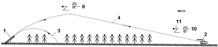 | Figure 4. Shooting at distant targets. Notation: 1 – gun; 2 – long distance target; 3 – conventional short distance trajectory of the non-wing projectile; 4 – long distance trajectory of wing projectile; 9. 10 – TV transmitter; 11 – signal of transmitter (image of result) |
In this case the offered innovation allows using the rifled gun as the smoothbore gun. The projectile is thus not forced to rotate.The other innovation is the special powder cartridge (fig. 3a - (4)). In the conventional patron the gases have a speed limited by the speed of sound: the bullet/projectile cannot reach the speed more 1000 – 2000 m/s in any long barrel. In this proprietary design, the special powder cartridge (4) is placed inside the patron between the bottom of patron and bullet/shell. This cartridge connects to the projectile. In this case the part of powder (into cartridge) will be accelerated together with projectile and pressure (acceleration) will be high pushed by the end of barrel (rocket effect, fig.3b). The projectile speed will be significantly more. In addition the longer the gun barrel, the longer the length of cartridge (fig. 3c) and significantly increases the speed of the projectile. After shooting the cartridge is discarded (fig. 3d).The shooting from offered gun is shown in fig. 4. If distance is very long, the projectile launches in top of trajectory the micro-transmitter 9 having small parachute. In moment of explosion the projectile launches the TV transmitter 10 (fig.4), which is transmitting the TV image (11) (result of shooting).List of some innovations:1. Special forms of bullet/shell and wings which increase the range of projectile in 2 – 5 times.2. The light free rotated sealing O-ring (for rifled gun). 3. Additional special cartridge inside of patron which significantly increases the barrel speed of projectile.4. Guidance and recognizing of a target image.5. TV transmitting of shot results.Advantages:1. Increasing the range in 2 – 5 times.2. No any changes in guns/rifles. The change is ONLY in projectile (bullet/shell or patron).3. Using any rifled or non-rifled guns.4. New type of projectile guidance (recognizing of target).5. Transmitting of shot result.
3. Theory of Flight Bullet/Shell and a General Estimation of Range
(In metric system)1. The maximum range, R, of flight bullet/shell is obtained from the kinetic energy of theoretical mechanics for ratio lift/drag K = const. It is equals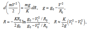 | (1) |
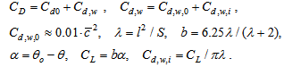
where R is range[m]; R0 = 6,378.106 is the Earth’s radius[m]; K is the average aerodynamic efficiency (K = 6–18 for subsonic bullet/shell and K = 2–5 for supersonic bullet/shell; go = 9.81 m/s2 is gravity; V1 is muzzle speed of projectile[m/s]; V0 < V1 is final (near aim) speed[m/s] (V0 = 40–60 m/s) of projectile; V is variable speed, V0 < V < V1[m/s]. For estimation average V = 0.5(V1+V0); mg/K = D is air drag[N]; m is bullet/shell mass[kg]. For V < 2000 m/s, variable gravity g ≈ go. Last equation in (1) is obtained from the first equation using integration.The ratio K approximately equals: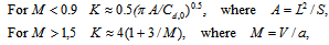 | (2) |
Here M is Mach number; L is wing span, m; S is wing area, m2; a is sound speed, at H = 0, T = 0oC a = 330 m/s; for T = 20oC a = 342 m/s. For H > 11 km a ≈ 295 m/s; Cd,0 is the projectile drag coefficient for attack angle = 0.Results of computations for subsonic (V < 300 m/s, M < 0.9, M is Mach number) and supersonic vehicles are presented in Figs. 5 and 6. The range of a subsonic shell is 30–60 km for V1 = 300 m/s (fig.5); the range of a supersonic shell can reach 400–1000 km for V1 = 2000 m/s (fig.6).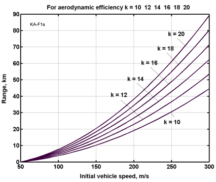 | Figure 5. Range of the subsonic projectile versus initial speed for different aerodynamic efficiency K =4 - 16 |
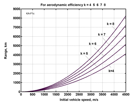 | Figure 6. Range of the supersonic projectile versus initial speed for different aerodynamic efficiency K = 2 3 4 5 |
2. Average speed and flight time are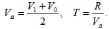 | (3) |
3. Computation of the complex trajectory used the high altitude.Accuracy equations of ballistic trajectory are: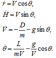 | (4) |
For subsonic speed (M < 0.9) | (5) |
where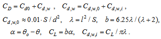 For supersonic and hypersonic speed (M > 1.5)
 | (6) |
 | (6a) |
where r is range of projectile flight, m; V is projectile speed, m/s; H is projectile altitude, m; θ is trajectory angle, radians; D is projectile drag, N; m is projectile mass, kg; g is gravity at altitude H, m/s2; L is projectile lift force, N; t is flight time, sec.; CL is lift force coefficient, for subsonic speed CL = 0 - 3.5 , for supersonic speed CL ≈ 4α , where α is the wing attack angle, rad; CD is air drag coefficient. For supersonic wing CD ≈ α2; a ≈ 295 m/s for H > 11 km is sonic speed in atmosphere; S is wing area, m2; ρ is the air density, for H = 0 ρo = 1.225 kg/m3. For H = 0 - 100 km ρ ≈ ρo exp(-1.4.10-4). We take Cd0 = 0.136 for M < 0.9 and Cd0 = 0.473 for M > 1.2 . is relative thickness of wing ≈ 0/05 – 0.1 .ProjectsResults of computations are presented below for the different shells and bullets and in Table 1. No optimization of range. Guidance: For rotational shells the full path, and for non-rotating - at the rising part of the trajectory the angle of attack is (6)’ and at the gliding part the angle is maximum K. | Table 1. Results of computation |
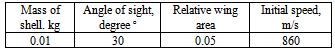
| | Type of Gun | Type of shell, W-is wing | Caliber mm | Mass of shell. kg | Angle of sight,degree o | Relative wing area | Initial speed, m/s | Final speed, m/s | Range, km | Flight time, sec | Ratio Lift/drag for M<0.9 or M >1.2 | Number of Fig. | | Rifle | Non W | 7.62 | 0.01 | 5 | 0 | 860 | 170 | 2.361 | 7.84 | K=0 | Fig.7-1 | | | Wing | 7.62 | 0.01 | 5 | 0.05 | 860 | 49 | 6.852 | 78 | K=4 | Fig.7-2 | | | Wing | 6/7.62 | 0.01 | 5 | 0.05 | 860 | 62 | 9.718 | 88 | K=4 | Fig.7-3 | | Rifle | Non W | 7.62 | 0.01 | 30 | 0 | 860 | 121 | 4.062 | 28 | K=0 | Fig.7-1 | | | Wing | 7.62 | 0.01 | 30 | 0.5 | 860 | 33.5 | 9.890 | 220 | K=4 | Fig.7-2 | | | Wing | 6/7.62 | 0.01 | 30 | 0.5 | 860 | 42.6 | 14.10 | 243 | K=4 | Fig.7-3 | | M109 | Non W | 107 | 15 | 30 | 0.3 | 494 | 253 | 9.432 | 36.8 | K=0 | Fig.8-1 | | | Wing | 107 | 15 | 30 | 0.3 | 494 | 91 | 40 | 354 | K=8 | Fig.8-2 | | M107 | Non W | 155 | 44 | 30 | 0.3 | 600 | 314 | 15.64 | 48.6 | K=0 | Fig.9-1 | | | Wing | 155 | 44 | 30 | 0.3 | 600 | 108 | 66 | 463 | K=8 | Fig.9-2 | | Gun | Non W | 406 | 1000 | 30 | 0.3 | 800 | 445 | 34.9 | 71.2 | K=0 | Fig.10-1 | | | Wing | 406 | 1000 | 30 | 0.3 | 800 | 199 | 140 | 484 | K=8 | Fig.10-2 | | M168 | Non W | 20 | 0.102 | 30 | 0.3 | 1050 | 149 | 5.896 | 33.8 | K=0 | Fig.11-1 | | | Wing | 20 | 0.102 | 30 | 0.3 | 1050 | 40 | 24.9 | 500 | K=8 | Fig.11-2 | | Anti-tank | Non W | 84 | 6.7 | 8 | 0.3 | 290 | 240 | 2.088 | 8 | K=0 | Fig.12-1 | | Antank | Wing | 84 | 6.7 | 8 | 0.3 | 290 | 131 | 8.636 | 47.1 | K=4 | Fig.12-2 |
|
|
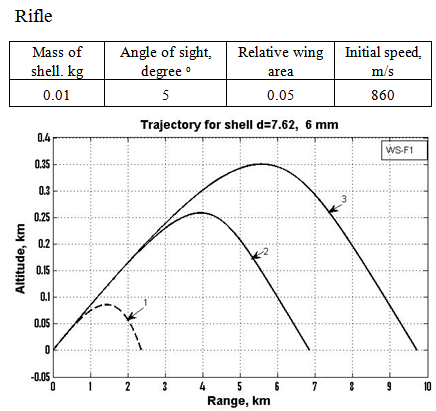 | Figure 7a. Rifle d = 7.62 mm and 6/7.62. 1 – d = 7.62 mm, non Wing; 2 - d = 7.62 mm, Wing; d = 6/7.62 mm , Wing, 6 is sub-caliber |
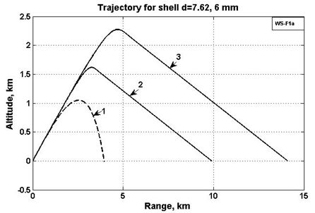 | Figure 7b. Rifle d = 7.62 mm and 6/7.62. 1 – d = 7.62 mm, non Wing; 2 - d = 7.62 mm, Wing; d = 6/7.62 mm , Wing; 6 is sub-caliber |
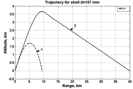 | Figure 8. Howitzer M109, d = 107 mm, M = 15 kg, θ = 30o, Vo = 494 m/s, S = 0.3 , K = 8. 1 – Conventional shell; 2 – Shell has wing |
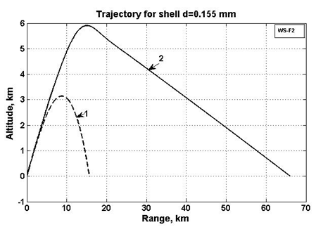 | Figure 9. Howitzer M107 d = 155 mm, M = 44 kg, θ = 30o, Vo = 600 m/s, S = 0.3, K = 8. 1 – Conventional shell; 2 – Shell has wing |
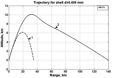 | Figure 10. Big warship gun, d = 406 mm, M = 1000 kg, θ = 30o, Vo = 800 m/s, S = 0.3 , K = 8. 1 – Conventional shell; 2 – Shell has wing |
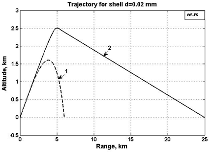 | Figure 11. Anti-aircraft gun M168, d = 20 mm, M = 0.1 kg, θ = 30o, Vo = 1050 m/s, S = 0.3 , K= 8. 1 – Conventional shell; 2 – Shell has wing |
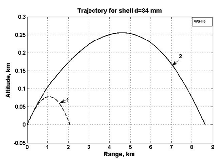 | Figure 12. Anti-tank, d = 84 mmM = 6,7 kg, θ = 8o, Vo = 290 m/s, S = 0.3 , K = 4. 1 – Conventional shell; 2 – Shell has wing |
4. Conclusions
New forms of shells/bullets which increases range of the projectiles 2 – 5 times is described. These forms contain in its design small special wings and stabilizers. The shell/bullet special form wings support the projectile in air, so that unlike conventional bullets or shells at that distance, these do fall to earth’s surface and the projectile maintains significant kinetic energy. The important innovation is its compatibility with the conventional rifles and gun with rifled barrel. The second idea is radical change of trajectory. The projectile reaches a high altitude and glides from height using wings with subsonic speed and a good ratio lift/drag.Author developed the theory of these projectiles and computed some projects which show high efficiency of this innovations. These bullets and shells can be quickly integrated into the arms industry and army because it does not require manufacture of new weapons (rifles, guns), but only change the bullets and shells.Author also suggests for this systems: the light free rotated sealing O-ring (for rifled gun); additional special cartridge inside of patron which significantly increases the barrel speed of projectile; guidance by recognizing of a target image; TV transmitting of shot results.The reader also find an information about this topic in[8]-[17].
ACKNOWLEDGEMENTS
The author wishes to acknowledge Shmuel Neumann (Israel) for correcting the English and offering useful advice and suggestions.
References
| [1] | Bolonkin A.A., New Methods of Optimization and Their Applications, Moscow, MHTU, 1972, 220 ps. (in Russian). |
| [2] | Bolonkin A.A., Methods of Optimization, Work presented to AIAA/NASA/USAF/SSMO Symposium on Multidisciplinary Analysis and Optimization, 7 – 9 September 1994, Panama City, FL, USA. |
| [3] | Bolonkin A.A., Optimal Trajectories of Air and Space Vehicles. Journal “Aircraft Engineering and Space Technology. Vo.76, No.2, 2004, pp.193-214. |
| [4] | Bolonkin A.A., Non-Rocket Space Launch and Flight. Elsevier, 2006, 468 ps. Attn. 4, pp.368-423. http://www.archive.org/details/Non-rocketSpaceLaunchAndFlight , http://www.scribd.com/doc/24056182 . |
| [5] | Bolonkin A.A., “New Concepts, Ideas, Innovations in Aerospace, Technology and the Human Sciences”, NOVA, 2006, 510 pgs.http://www.scribd.com/doc/24057071,http://www.archive.org/details/NewConceptsIfeasAndInnovationsInAerospaceTechnologyAndHumanSciences. |
| [6] | Bolonkin A.A., Cathcart R.B., “Macro-Projects: Environments and Technologies”, NOVA, 2007, 536 pgs. http://www.scribd.com/doc/24057930 . http://www.archive.org/details/Macro-projectsEnvironmentsAndTechnologies |
| [7] | Bolonkin A.A., Femtotechnologies and Revolutionary Projects. Scribd, USA, 2011. 538 p. 16 Mb. http://www.scribd.com/doc/75519828/ http://www.archive.org/details/FemtotechnologiesAndRevolutionaryProjects |
| [8] | Bolonkin A.A., LIFE. SCIENCE. FUTURE (Biography notes, researches and innovations). Scribd, 2010, 208 pgs. 16 Mb. http://www.scribd.com/doc/48229884, http://www.archive.org/details/Life.Science.Future.biographyNotesResearchesAndInnovations or http://www.lulu.com , orhttp://www.publishamerica.net/sc/productsearch.cgi?search_field=Bolonkin&storeid=*1ed736148e14b9de8c3184b7f08fb4a634 , orhttp://www.amazon.com/s/ref=nb_sb_noss?url=search-alias%3Dstripbooks&field-keywords=Bolonkin&x=12&y=19 . |
| [9] | Bolonkin A.A., Femtotechnology: Nuclear AB-Material with Fantastic Properties. http://www.scribd.com/doc/24046679/ , American Journal of Engineering and Applied Science, Vol. 2, #2, 2009, pp.501-514. |
| [10] | Bolonkin A.A., Femtotechnology: Design of the Strongest AB-Matter for Aerospace Journal of Aerospace Engineering, Oct. 2010, Vol. 23, No. 4, pp.281-292. http://www.archive.org/details/FemtotechnologyDesignOfTheStrongestAb-matterForAerospace http://www.scribd.com/doc/57369206/Femtotechnology-Design-of-the-Strongest-AB-Matter-for-Aerospace |
| [11] | Bolonkin A.A., Converting of Any Matter to Nuclear Energy by-AB-Generator American Journal of Engineering and Applied Science, Vol. 2, #4, 2009, pp.683-693. http://www.scribd.com/doc/24048466/ |
| [12] | Bolonkin A.A., Converting of any Matter to Nuclear Energy by AB-Generator and Aerospacehttp://www.archive.org/details/ConvertingOfAnyMatterToNuclearEnergyByAb-generatorAndAerospace http://www.scribd.com/doc/57419950/Converting-of-Matter-to-Nuclear-Energy-by-AB-Generator-and-its-Application |
| [13] | Bolonkin A.A., Femtotechnology: AB-Needles. Fantastic properties and Applications. Scripd, 2010, http://www.scribd.com/doc/55054819/ ,http://vixra.org/abs/1111.0064http://www.archive.org/details/FemtotechnologyAb-needles.FantasticPropertiesAndApplications Published in collection: Propulsion: Types, Technology and Applications. NOVA. 2011.https://www.novapublishers.com/catalog/product_info.php?products_id=24848 |
| [14] | Bolonkin A.A., Review of new ideas, innovations of non-rocket propulsion systems for Space Launch and Flight (Part 1). http://www.scribd.com/doc/54655572/ , http://www.archive.org/details/ReviewOfNewIdeasInnovationOfNon-rocketPropulsionSystemsForSpace |
| [15] | Bolonkin A.A., Air Catapult Transportation. NY, USA, Scribd, 2011.http://www.scribd.com/doc/79396121/Article-Air-Catapult-Transportation-for-Scribd-1-25-12, http://www.archive.org/details/AirCatapultTransport |
| [16] | Bailey, J B A (2004). Field Artillery and Firepower. AUSA Institute of Land Warfare book. Annapolis, MD: Naval Institute Press. ISBN 978-1-59114-029-0. OCLC 51931033. |
| [17] | Wikipedia. Artillery. Shell. http://www.Wikipedia.org |
 Abstract
 Reference
 Full-Text PDF
 Full-text HTML