-
Paper Information
- Next Paper
- Previous Paper
- Paper Submission
-
Journal Information
- About This Journal
- Editorial Board
- Current Issue
- Archive
- Author Guidelines
- Contact Us
International Journal of Aerospace Sciences
2012; 1(4): 68-76
doi: 10.5923/j.aerospace.20120104.03
Embedding an Exoskeleton Hand in the Astronaut’s EVA Glove: Feasibility and Ideas
 Abstract
 Reference
 Full-Text PDF
 Full-Text HTML
Alain Favetto 1, 2, Elisa Paola Ambrosio 1, Silvia Appendino 1, Alessandro Battezzato 1, Fai Chen Chen 1, 3, Diego Manfredi 1, Mehdi Mousavi 1, 3, Francesco Pescarmona 1
1stituto Italiano di Tecnologia, Corso Trento 21, 10129 Torino, Italy
2Dipartimento di Automatica e Informatica, Politecnico di Torino, Corso Duca Degli Abruzzi 24, 10129 Torino, Italy
3Dipartimento di Meccanica, Politecnico di Torino, Corso Duca Degli Abruzzi 24, 10129 Torino, Italy
Correspondence to: Alain Favetto , stituto Italiano di Tecnologia, Corso Trento 21, 10129 Torino, Italy.
| Email: |  |
Copyright © 2012 Scientific & Academic Publishing. All Rights Reserved.
This paper investigates the key factors associated to the realization of a hand exoskeleton to be embedded in an astronaut’s EVA glove, in order to overcome the stiffness of the pressurized space suit. An overview regarding the main constraints related to the realization of a hand exoskeleton for EVA suits is provided, as well as a preliminary concept analysis of possible solutions in terms of mechanical structure, actuators and sensors. Furthermore, analyses of human hand kinematics and of the characteristics of the EVA glove’s stiffness are presented, as a basis for design and dimensioning of the exoskeleton. The future exoskeleton will be a complex mechatronic system detecting the operator’s movement through sensors, processing the acquired data and generating the motion through its actuation system.
Keywords: EVA Glove, Space Suit, Hand Exoskeleton, Human Hand, Effect on Hand Fatigue, Effect on Hand Strength
Cite this paper: Alain Favetto , Elisa Paola Ambrosio , Silvia Appendino , Alessandro Battezzato , Fai Chen Chen , Diego Manfredi , Mehdi Mousavi , Francesco Pescarmona , "Embedding an Exoskeleton Hand in the Astronaut’s EVA Glove: Feasibility and Ideas", International Journal of Aerospace Sciences, Vol. 1 No. 4, 2012, pp. 68-76. doi: 10.5923/j.aerospace.20120104.03.
Article Outline
1. Introduction
- Extra Vehicular Activities (EVAs) are operations performed by astronauts away from Earth and outside spacecrafts. In order to operate in such harsh conditions, astronauts are equipped with spacesuits composed of a complex and highly technological multilayer structure[1]-[3]. The suit must also protect from the vacuum outside, thereby it is internally pressurized. Such factors impose strong limitations to the astronaut’s mobility during a mission, increasing the stiffness of each joint and requiring the astronaut to exert greater-than-normal forces to perform even the simplest movements. Gloves are probably the most critical part of the space suit because almost all operations require the use of hands. One of the main problems limiting the overall duration of a spacewalk is the astronaut`s hand fatigue. A device able to overcome (or prevent) hand fatigue during EVA would be a significant improvement for the astronauts, allowing them to accomplish their tasks more efficiently, more comfortably and for a longer time. In the forthcoming years, NASA plans to significantly increase the number of hours dedicated to EVA operations during space missions[4], as shown very clearly in Figure 1. Therefore, the importance of this kind of device is evident. This study is a preliminary approach towards a possible technological solution able to reduce the fatigue of the astronaut’s hand avoiding interference with its natural movements. The final goal is the realization of a prototype of a lightweight hand exoskeleton to be embedded in the astronaut’s gloved hand, in order to overcome the stiffness of the pressurized suit. Both the high complexity of the human hand, in terms of degrees of freedom and working space, and the extreme environment in which the exoskeleton will have to work create a series of different constraints increasing the complexity of the project.
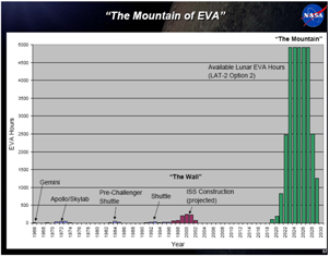 | Figure 1. “The mountain of EVA”[3] |
2. Application Environment: Issues and Constraints
- The embedding of the exoskeleton inside the EVA glove changes the application environment of this project from the space to the glove itself. This means that some problems and constraints related to the space environment, for example radiation and cosmic dust, become less incisive, because they are screened by the protective multilayer system, while other issues related to dimensions and working space arise. The main constraints related to the application scenario are analyzed below.
2.1. Dimension and Weight
- The final dimensions and weight of the exoskeleton are a major constraint on the choice of each component, particularly those related to the actuation system and structural materials. Nowadays exoskeletons found in literature[5]-[8] or commercially available are generally bulky because they are built for tasks, such as rehabilitation or virtual reality, that do not impose strong size limits, especially on the rear side of the hand. Embedding the exoskeleton inside the glove imposes a strong limit on its size. A possible further step of the project, in case the exoskeleton would become a necessary part of the astronaut’s equipment, could be redesigning the glove itself, in order to reduce the overall size limit. Moreover, low mass and inertia are important requirements in order to facilitate manipulation tasks.
2.2. Working Space and Self Interference
- A critical point in the development of an exoskeleton for an EVA glove is avoiding excessive restrictions to the work space, and hence to the operator’s dexterity. The palm should be as free as possible, in order to avoid limiting the ability to grasp and handle objects, so it is strongly preferable to place all the systems within a small space on the back of the hand. Furthermore the lateral thickness at each finger must be minimal in order to allow finger abduction. All these shape factors limit the structure and the technologies that can be used.
2.3. Degrees of Freedom
- The hand is a very complex limb with 24 degrees of freedom in a significantly reduced space. The faithful reproduction of every single possible movement is difficult to obtain with a robotic structure, especially under the constraints related to weight, size and dimensions analyzed above. Another big challenge arises considering the first joint of the thumb that causes the displacement of a great portion of the palm. Therefore, there are two opposite requirements: the desire to ensure high dexterity to the operator creating a structure with many joints, and the need to create a device with limited size and weight. A compromise should be found, since it is hardly possible to actuate and sense 23 DoFs in an appropriate way, and conversely it would be useless to create a basic device with few degrees of freedom that would not help the operator. Studying the different movements that the hands can perform during typical tasks, the number of active DoFs of the exoskeleton can be reduced by appropriate kinematic dependencies and by the use of passive joints.
2.4. Space Environment
- Space is a highly dynamic environment that poses threats[9] related to several aspects. This must be taken into account in the choice of the components and materials of the exoskeleton. The glove and the suit in general guarantee a certain level of protection through a multilayer system. Despite the protective layers, some problems related to the space environment still persist such as cosmic dust, electromagnetic interferences, high temperature variations, micro-meteoroids.Cosmic dust is composed by particles which are molecules up to 0.1 µm in size. Due to their small dimensions, they might penetrate through the seals of space suits causing many problems related to the astronaut’s health or to the mechanical parts. Electromagnetic interference may be due to different factors: solar activity, high energy particles, electromagnetic radiation, or space plasma. All these agents can degrade or damage the devices and also cause background noise possibly leading to permanent damage and component failure. Sensors in particular are very sensitive therefore a high level of background noise can make the data useless.Micro-meteoroids are small particles travelling with high relative velocity trough space: they can be dangerous upon direct impact.Finally, energy consumption is a main issue: space scenario strictly requires that the exoskeleton uses as little energy as possible in order to increase autonomy and to allow using smaller batteries.
2.5. Comfort
- Last but not least is the comfort factor that the glove must guarantee to the operator, since the astronaut will have to withstand a high amount of hours in EVA. Today some astronauts have already experienced some physical damage from gloves such as parastesia, loss of feeling in fingers, abrasions, loss of nails[10]. Therefore it is important that the comfort level guaranteed by the exoskeleton is as high as possible, otherwise fatigue reduction would correspond to an increment in the risk of hand injuries.
3. Preliminary Design Concepts
- The first step to focus on in order to create a hand exoskeleton is a detailed analysis of the static and dynamic characteristics of the hand and the effect that the glove has on hand activities. The main problem related to the hand is due to the large number of degrees of freedom and the relatively high variation in the characteristics in terms of strength, size and dexterity between different individuals.
3.1. Analysis of Finger/Hand Geometry
- Despite variations in size, the hand can be uniquely described by a kinematic chain whose joints are placed in the same position as the various articulations and whose links appear to be the bones[11]-[12]. The kinematic model of the hand can be represented by 19 links and 24 DoFs corresponding to the bones and articulations respectively. Each finger, excluding the thumb, can be modelled as a kinematic chain composed of four links, three of which have joints with almost parallel axes (MCP, PIP, DIP), involved in flexion and extension movements, and one perpendicular to them involved in the movement of abduction. The thumb is much more complex because its movements also strongly involve the metacarpal bone. The scheme of the correspondence between hand anatomy and its kinematic structure is presented in Figure 2.
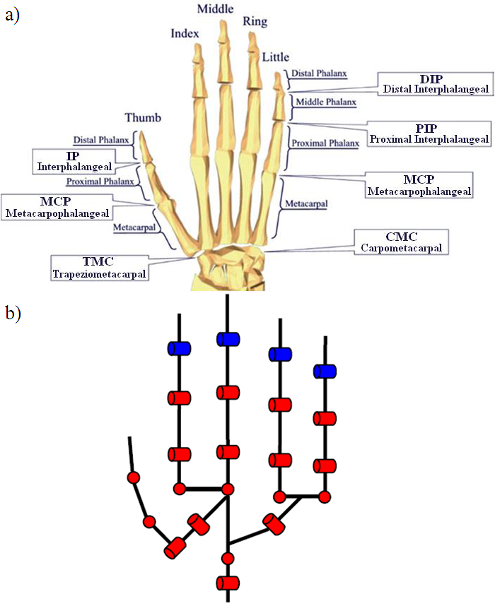 | Figure 2. Human Hand a) Articulation and Phalanges b) Kinematic structure |
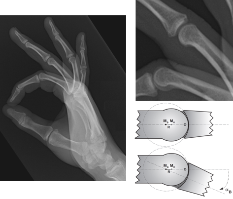 | Figure 3. Human knuckles behaviour[13] |
 | Figure 4. The problem of joint axes[14] |
3.2. Analysis of forces and Velocities
- The analysis of forces and velocities is required in order to properly dimension sensors and actuators. It is necessary to know the respective ranges because over dimensioning the devices directly implies having larger masses and weights, while under dimensioning them means not being able to follow all natural capabilities of the fingers. In literature there are several studies on forces and velocities of the hand. The important ones for dimensioning are presented in the tables hereunder: maximum forces, maximum torques, and maximum velocities for each phalanx [15]-[18].
|
|
|
3.2.1. Effect of EVA Glove on Hand Performances
- A preliminary analysis of the effect of EVA glove on the human hand strength and fatigue has been done[23]. The EVA glove used during the tests is a left hand Russian Orlan-DM. Tests have been performed involving the participation of 13 volunteer test subjects, who had never worn an EVA glove before. Four different hand tasks have been performed barehanded and wearing the EVA glove in pressurized and unpressurized conditions. The tasks have been chosen, among all grips and pinches, in order to cover different grips and to vary the number of involved fingers and muscles:a) Power grip: power grasp performed with all four fingers opposing the thumb;b) Two-Finger pinch: precision pinch that involve the thumb and the index finger;c) Three-finger pinch: precision grip that involve the index and the middle finger opposing the thumb;d) Lateral pinch: intermediate pinch that involve the thumb opposing the side of the fist.
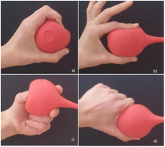 | Figure 5. The four tasks chosen for the tests. a) power grip, b) two finger pinch, c) three finger pinch,d) lateral pinch |
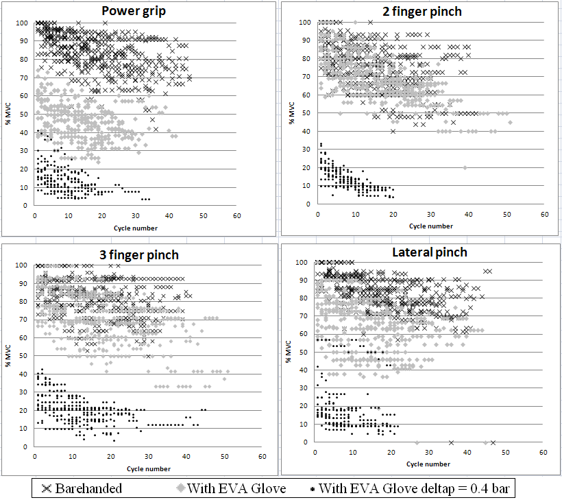 | Figure 6. Effect of wearing the EVA glove. a) Effects of wearing the EVA glove in different conditions on power grip performances. b) Effects of wearing the EVA glove in different conditions on two-finger pinch performances. c) Effects of wearing the EVA glove in different conditions on three-finger pinch performances. d) Effects of wearing the EVA glove in different conditions on lateral pinch performances |
3.2.2. Stiffness of the Glove
- A preliminary analysis of the EVA glove stiffness and of the force applied on the hand by the glove has been carried out[23].. Through an appropriate distributed sensor system, the pressure acting on the hand when simulating the four tasks described above has been recorded barehanded and wearing the EVA glove. The integral of the pressure on the surface of the hand provides a first quantitative idea of the resisting force the EVA glove exerts. Figure 7 shows the Russian Orlan-DM EVA glove on the left and its maximum effect during a power grip test.Distinguishing the forces applied on each phalanx and measuring the position of the centre of forces it is possible to obtain the torque applied by the glove on each joint, and thus to dimension the actuation system.
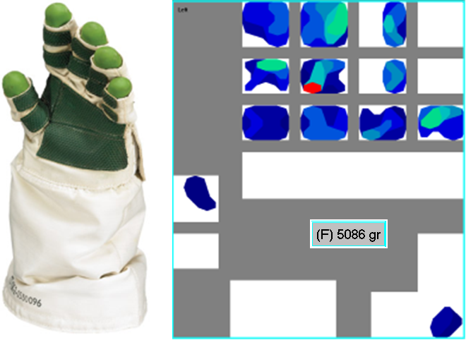 | Figure 7. Pressure distribution in a power grip movement wearing the EVA glove |
4. General Concepts for Exoskeleton Design
- The preliminary analysis allows to depict the specifications of each element of the exoskeleton and to evaluate possible strategies. An exoskeleton is a complex mechatronic system; thereby the following paragraphs will focus on its structure, actuation and sensorization.
4.1. Structure
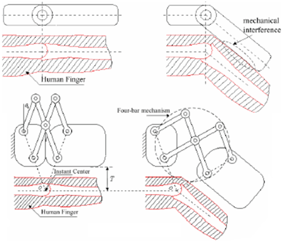
- The structure provides support, aid and guidance to the fingers, ensuring the correct kinematics, so to achieve the correct transmission of the movements from the actuators. Moreover, the choice of an appropriate and well designed structure will allow simple integration between sensors and actuators. The analysis of a possible geometry is fundamental to optimize weight and force transmission. Whereas an extremely lightweight structure seems to be an advantage, the structure has to address correctly forces and torques to avoid stressing the operator’s articulations. Many issues are involved in the determination of the type of structure that it is to be realized: the choice of the right material, the number of active and passive degrees of freedom, the decision on how to overcome the problem of the axes of rotation and the choice of how to transmit the forces from the actuators. Figure 8 depicts two different exoskeleton structures. The structure on the left uses a four bar mechanism to move the joints and the structure on the right use a cable mechanism.
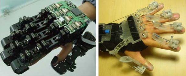 | Figure 8. Two different exoskeleton structures: Four bar mechanism (left)[14] and Cable mechanism (right) |
4.2. Actuators
- The actuators generate the movement of the links around joints according to the command signals given by a control unit. The actuation part is a critical point in the project, since usually the dimensions of an actuator are strictly related to the power and torque that it is able to generate. The specifications of speed, from the study of the hand, and of forces, from the study of the EVA glove, provide a first idea about the actuators to be used. There are numerous types of actuators based on different technologies: using high-pressure fluids such as hydraulic or mesofluidic ones, using compressed air, as pneumatic muscles, relying on magnetic fields and many others. Although the wide variety of available technologies, the solutions that may be considered for this specific application are a very few, mainly due to the following factors: space environment (as described previously), factors related to the safety of the astronauts (e.g. high pressure liquids or gases cannot be used inside a space suit), and finally constraints in terms of energy consumption, robustness against magnetic fields, dimensions and weight.The wire actuation allows occupying as little space as possible around the hand by placing the actuation system in a non critical position. The choice of a specific typology of actuators can be neglected at this stage of the study by assuming to be able to apply a known and controllable action on the structure.
4.2.1. Transmission
- As mentioned above, the proposed transmission is achieved by mono-directional wires, which pull each phalanx to reproduce the flexion movement. The extension movement is obtained by passive elements placed inside the structure and coaxial with the joints. A possible example of passive elements could be represented by elastic components that can be real components, e.g. torsion springs, or factitious elements that act like an elastic components, e.g. the intrinsic stiffness of the EVA glove.
4.3. Sensors
- The sensors allow the perception of quantities of interest based on which the control actions will be generated. The quantities of interest involved in the development of a hand exoskeleton are torques and/or forces and the relative positions of the various joints of the fingers. There are many types of sensors that differ in the technology they use: piezo-resistive, load cells, capacitive. Even in this case, the constraints are related to the problems of energy consumption, electromagnetic robustness, size and weight. The positioning of sensors is an additional issue, related to the kind of sensor used and to the specific application (e.g. pressure sensors outside the EVA glove could be used for tactile feedback on object manipulation, whereas pressure sensors inside the EVA glove could be used for tracking control). An interesting possibility is given by surface electro-miographical (sEMG) sensors, which measure the user’s muscular electrical potentials, which convey the muscular contraction commands. A great advantage of using sEMG sensors is that the signals are proportional to the force that the human being desires to apply trough his muscles. This kind of sensor could be used as a force sensor with the great advantage of being placed not on the hand but on the forearm, where most of the finger-actuating muscles reside.
5. Preliminary Control Concepts
- The latter elements interact with each other by means of the control system. The sensors detect the desired quantities and then their signals are processed by the control system, which decides how to act on the structure by means of the actuators. A simple control strategy could be to use tracking control: the astronaut transmits their will to perform a given movement by acting on the structure. This is detected by pressure sensors between finger and exoskeleton, and the control issues the appropriate commands to the actuators in order to follow and assist the desired astronaut’s movements and bring back the sensor reading to a predefined value. Using a couple of sensors for each degree of freedom (one inside and one outside the exoskeleton) would also allow to distinguish free motion (where only the signal of the internal sensor changes) from a grasp situation (in which both the internal and the external sensor would be loaded).It is interesting to note that two control loops work in parallel at the same time in an exoskeleton system.
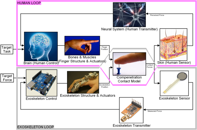 | Figure 9. General control scheme |
6. Conclusions and Future Work
- This paper summarizes the preliminary analyses done in order to study and verify the feasibility of a hand exoskeleton designed to be embedded in an astronaut’s glove to overcome its stiffness. Currently a single finger prototype has been designed and will soon be realized. The structure, the sensors and the actuators used in the design of the finger will then be redesigned on the basis of the results obtained and integrated in a wider project, taking into account the constraints and limitations described in the present paper. Finally the complete exoskeleton hand prototype will be realized.