H. R. Behzadi 1, 2, M. Qaryan 2, A. Samadi 2, H. Davoodi 3
1University of Technology, Isfahan, Iran
2Parto PardazeshEspadanCompany, Isfahan, Iran
3Ragheb Esfahani Institution
Correspondence to: H. R. Behzadi , University of Technology, Isfahan, Iran.
| Email: |  |
Copyright © 2012 Scientific & Academic Publishing. All Rights Reserved.
Abstract
Thispaper introduces new method and apparatus for measuring strength of optical windows and domes that use in flying vehicles such as satellite and missiles. There are different methods for measuring strength such as 3-point and 4-point flexure test, equibiaxial disk flexure test, ring-on-ring and ball-on-ring.This apparatus can test all optical material strengthsthatare used in windows and domes with different aerodynamic shapes. This method can measure windows or domes strength by considering thermal effects at hi-speed application, thermal shock, aerodynamic design, internal pressure and simulating all these conditions. Also, experimental results provided by this apparatus showed same measuring results for equivalent samples and also represented impact of aerodynamic design in material strength.
Keywords:
Flexure, Satellite, Strength, Thermal, Dome, Window
Cite this paper:
H. R. Behzadi , M. Qaryan , A. Samadi , H. Davoodi , "A New Method for Measuring the Strength of Materials Used in Optical Windows and Domes", International Journal of Aerospace Sciences, Vol. 1 No. 4, 2012, pp. 64-67. doi: 10.5923/j.aerospace.20120104.02.
1. Introduction
Windows and domes are optical elements used in outer part of optical systems. They protect inner optical and electrical parts from environment damages such as impact with solid particles or water drops, thermal effects at hi velocities, thermal shocks, atmospheric pressures and erosions. When satellites or missiles fly at high speeds, domes or windows must have enough resistance to atmospheric pressure. Therefore, awareness about strengths of optical material applied for design windows or domes is essential. The strength of a brittle material is defined as the stress at which the material fails. The strength is also called the modulus of rupture, or MOR. For metal, the strength of similar pieces(same fragments of brittle materials) is reproducible. For ceramics, the strength of seemingly identical pieces is highly variable. As the strength of a ceramic is governed by the presence of defects, it is plausible that a given stress operating over a large area be more likely to encounter a strength limiting defect than the same stress operating over a small area. That is, large objects tend to fail at lower stress than small objects[1]. Suppose that we test a series of disks in ring-on-ring flexure with a load area of A1 and find an average strength S1. If we test a second set of the same kind of disks using a load area A2 (>A1), the strength S2 will be lower[2,3]: | (1) |
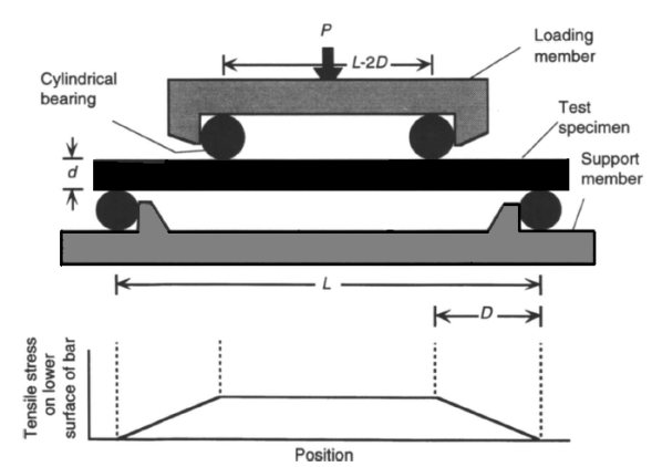
Where m is Weibull modulus. It is dangerous to quote the strength of a material, since it depends on the type and quality of surface finish, material fabrication method, material purity, test method, and specimen size[1]. Strength is not an intrinsic, invariable property of an ideal material[1].In reporting the strength of materials, we can see difficulties. Also, strength depends on the temperature. Many ceramics lose their strength with increase in temperature, and it is a very important factor in strength measuring.There are different flexure test for measuring strength of optical material such as 3-point flexure test, 4-point flexure test, ring-on-ring equibiaxial flexure test, ball-on-ring test and etc.A more successful approach is to bend a ceramic bar until it breaks, and thereby measure the flexure strength. The simplest approach to flexure testing is the 3-point bending test illustrated in figure 1, in which a load is applied at the top center of a test specimen with a rectangular cross section. When the bar flexes, the bottom surface is in tension and the top surface is in compression.Fracture normally originates at the tensile surface.A better measurement of strength is the 4-point flexure test in Figure 2[4, 5]. In this case, the tensile stress on the bottom (tensile) surface of the bar is constant between the two load points.A common problem with both the 3-point and 4-point bend tests is that fracture originates where stress is concentrated on the long edges of the tensile face, instead of on face. Therefore, the long edges should be uniformly chamfered (beveled) at a 45° angle, or rounded. In either case, the edge should be polished to the same quality finish as the face. Even with these precautions, edge failures of optically polished materials are common.The preferred measure of strength of an optical window or dome material is the ring-on-ring equibiaxial flexure test in figure3 because the face of the disk can be polished to similar specifications as an optical window.Several experimental and theoretical studies have investigated the stresses in ring-on-ring equibiaxial flexure test more closely[6-8]. In this paper new apparatus was introduced. We designed new apparatus that can measure strength of optical windows or domes accurately and simulate atmospheric pressure and thermal effects in measuring.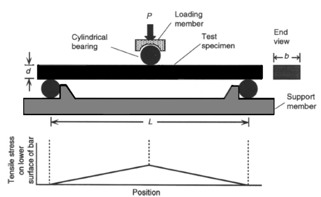 | Figure 1. Flexure strength measurement using 3-point bending |
 | Figure 2. Flexure strength measurement by 4-point bending |
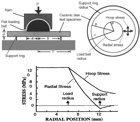 | Figure 3. Ring-on-Ring equibiaxial flexure test. Radial stress is along the radius and hoop stress is tangential |
2. Material and Method
Pressure loading in previous methods was not equal in whole area of testing samples. Also, if we can simulate thermal effects on samples during measuring process, we can measure strength accurately. Also, aerodynamic design has an influence on strength. This apparatus can measure strength of each sample with various shapes at different temperature. Schematic of this apparatus is shown in figure4.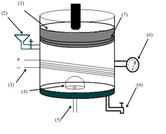 | Figure 4. The simple schematic of new apparatus for measuring strength of optical windows and domes that have been designed in PPScompany |
This apparatus have cylindrical body that is filled with oil from funnel form valve and is shown in figure with number(2) when the sample (4) stick with glue on circle plate in the bottom of cylindertest. This plateis connected with twists to cylinder and hasa pipe (5) that simulates internal pressure by the vacuum or air compressor pump if we want to examine windows strength for satellite or missile. This apparatus has a piston (1)that moves down for load pressure on sample by oil. The piston has several rings (7) to restrain oil in cylinder. Also, apparatus has electrical heater (3) for increasing oil temperature when we need to examine the strength of windows in various temperatures. Pressure monitor (6), displays inner cylinder pressure when the piston descends. When the pressure under piston increased, the pressure monitor displays increase in pressure until the sample is not able to withstand and will break. At breaking time pressure monitor shows decrease in internal pressure and this point shows the strength of samples.
3. Result and Discussion
Figure5 shows that the stress on the bottom window surface (or dome) is constant everywhere;it is one of the major advantages in this method.Also, in this method we can test aerodynamic windows like domes and consider influence of aerodynamic shape in strength. Figure6 show the places that windows or domes stick on it for measuring strength.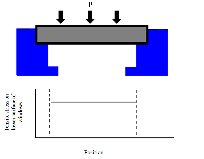 | Figure 5. Tensile stress on lower surface that measured using oil pressure |
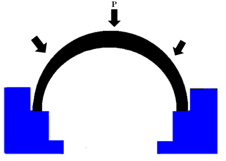 | Figure 6. Measurement of the strength of an aerodynamic window using the new apparatus |
Figure6 shows that the stress is equal for each location under the window surface.Figure7 shows one of the experimental results with plat windows in 27℃ temperature. The pressure was plotted as a function of time.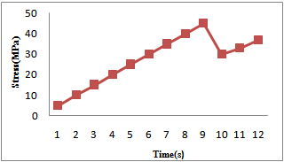 | Figure 7. Variation of pressure at 27℃ after 12 seconds for one optical window |
At beginning seconds,when cylinder fills with oil, piston move down and by decreasing in piston position, stress on window surface increases.After about 9 seconds, at about 43 MPa sample failed and pressure monitor shows decrease in inner apparatus pressure because empty space under sample filled with oil and inner apparatus pressure decreased. We repeated this method for the same samples;results were very similar while in current methods we usually have different results for same samples[1, 9]. For taking real results we have to modify speed of decrease in piston position and increase oil pressure on windows. Also, we can measure strength in hi-temperaturesinstantly and simulate flying condition by electrical heater that enwrap around the apparatus cylinder. Experiment results showed that samples with dome shape failed at upper pressure so the aerodynamic has influence in strength measuring.
4. Conclusions
Proposed method is accurate and can simulate flying condition for measuring strength such as thermal divergence, thermal shock, and internal pressure. In this method, loading pressure in whole area of samples is equal. The results for same samples are similar and optical designer can trust to its results for design optical windows and domes. Also this method can measure aerodynamic samples and it can consider this factor in measuring.
References
| [1] | Daniel C. Harris, “Materials for Infrared Windows and Domes: properties and performance”, SPIE, USA, 1999. |
| [2] | O. M. Jadaan, D. L. Shelleman, J. C. Conway, Jr., J. J. Mecholsky, Jr., and R. E. Tressler, “Prediction of the Strength of Ceramic Tubular Components: Part 1- Analysis,” J. Testing. Eval., 19, 181-191, 1991. |
| [3] | D. G. S. Davies, “The Statistical Approach to Engineering Design in Ceramics,”, Proc. Brit. Ceram. Soc.,m 22, 429-452, 1973. |
| [4] | G. D. Quinn, “Flexure Strength of Advanced Structural Ceramics: A Round Robin”, J. Am. Ceram. Soc., 73, 2374-2384, 1990.Online Available: http://journal.sapub. org/ajb. |
| [5] | MIL-STD-1942, Department of the Army, Washington, D. C., 1983. |
| [6] | D. K. Shetty, A. R. Rosenfield, P. McGuire, G. K. Bansal and W. H. Duckworth, “Biaxial Flexure Tests for Ceramics” , Ceram. Bull., 59, 1193-1197, 1980. |
| [7] | J. E. Ritter, Jr., K. Jakus, A. Batakis, N. Bandyopadhyay, “Appraisal of Biaxial Strength Testing”, J. Non-Crystalline solids, 38 & 39, 419-424, 1980. |
| [8] | W. F. Adler, D. J. Mihora, “Biaxial Flexure Testing: Analysis and Experimental Results”, Plenum Publishing Corp., New York, 1992. |
| [9] | R. W. Sparrow, H. Herzing, W. V. Medenica, M. J. Viens, “Influence of Processing Techniques on the VUV Transmittance and Mechanical Ptoperties of Magnesium Floride Crystal”, Proc. SPIE, 2286, 33-45, 1994. |
 Abstract
 Reference
 Full-Text PDF
 Full-Text HTML