M. Goodarzi , M. Rahimi , R. Fereidouni
Mechanical Engineering Department, Engineering Faculty of Bu-Ali Sina University, Hamadan, Iran
Correspondence to: M. Goodarzi , Mechanical Engineering Department, Engineering Faculty of Bu-Ali Sina University, Hamadan, Iran.
| Email: |  |
Copyright © 2012 Scientific & Academic Publishing. All Rights Reserved.
Abstract
In this study the concept of Active flow control using a blowing jet with a width of 2.5% of chord length which places on NACA0015 airfoil's upper surface under Re=455000 in 6 different angles of attack 12º to 17º is investigated. More than 200 numerical simulations are conducted over a range of parameters of jet locations (10%, 30% and 50% of chord from leading edge), jet velocity ratios (1, 2 and 6 time of free stream velocity) and jet angles (0º, 30º and 45ºrelative to the airfoil surface) are investigated. The viscous model used for modeling the turbulence is Spalart-Allmaras and a commercial CFD code, the FLUENT, is used to solve flow equations. Simulation results show that the blowing will increase the amount of lift and reduce drag. Also at high angles of attack, the blowing delay separation and improve the performance of the airfoil.
Keywords:
Flow Control, Blowing, NACA0015, CFD
Cite this paper:
M. Goodarzi , M. Rahimi , R. Fereidouni , "Investigation of Active Flow Control over NACA0015 Airfoil Via Blowing", International Journal of Aerospace Sciences, Vol. 1 No. 4, 2012, pp. 57-63. doi: 10.5923/j.aerospace.20120104.01.
1. Introduction
Man has never been satisfied with the world that surrounds him, and tried to control or improves it from the very beginning to get more beneficial effects. This applies to almost all science disciplines nowadays, and fluid Mechanics is not an exception. Since early times, fluid was an attractive and at the same time difficult to understand subject that forced investigators to improve their skills and knowledge. Even after understanding some of the complicated fluid behaviour investigators were never satisfied, and put also their efforts on controlling it. That’s where the discipline of Flow Control was born.The benefit of modern flow control techniques common to all of the areas is the ability to achieve large-scale changes in flow behaviour with low levels of energy input. This implies that some amplifying mechanism exists in the flow which the actuator triggers, enhances or suppresses in some way[1].Flow control provides the enabling technology for many of the advanced vehicles. Both passive and active technologies can play an important role. When changing flow conditions are not the critical issue, passive technologies offer the promise of simplicity. Active flow control enables optimization at off design conditions or when it becomes necessary to react to rapidly changing flow conditions[2].The benefits of flow control have become more importantas the nature of aircraft changes. With the advent of stealth the need for a method of control with fixed surfaces has grown. Also, economic interests have demanded more weight savings in the interest of fuel economy. This demand has lead to the demand for increased lift-to-drag ratios. Synthetic jets have made it possible to protect an aircraft from flow separation thus staving off the undesirable effects of stall. Stall leads to loss in lift and a tremendous increase in drag forces[3].During take-off and landing, the wings of airplanes have to generate an enormous amount of lift at low flight velocity. In modern commercial aircraft, this is realized by complex multi-element high-lift devices. As these cause additional weight, increased constructive effort, etc., there exists a significant economical interest in replacing the multi-element devices by single flaps. However, such flaps are only applicable if flow separation at high flap angles can be controlled. One possibility for active separation control is suction and/or blowing. Most applications incorporate excitation at the leading edge in order to affect the boundary layer upstream of the point of separation, with steady or periodic suction and blowing[4].By preventing separation, lift is enhanced and form drag is reduced. Suction and blowing of primary fluid can have significant effects on the flow field, influencing particularly the shape of the velocity profile near the wall and thus the boundary layer susceptibility to transition and separation[5].The first use of a steady air jet for lift enhancement in the United States was reported by Knight and Bamber (1929). Their experiments investigated the effect of the jet slot width, slot location, and air supply pressure inside the airfoil (which dictated the jet flow rate) on the increment in lift. They demonstrated a 151% increase in L/D for a conventional two-dimensionalairfoil[6].The momentum coefficient, first defined by Poisson-Quinton (1948) as  | (1) |
was found to be an effective scaling parameter for the dependence of the lift increment on the amplitude of jet-blowing actuators. In this definition  and
and  are the mass flow rate and velocity of the actuator jet, respectively, while
  is the dynamic pressure and S is the planform area[7].An extensive review of BLC research up to 1960 can be found in the two-volume monograph edited by Lachmann (1961)[8] and more recent by Mohammad Gad-el-Hak up to 2000[9].A large body of fundamental research used open-loop forcing to study optimum forcing frequencies and minimum forcing amplitudes necessary to maintain an attached flow, or to reattach a separated flow over a flap or an airfoil. Some early fundamental work was by Katz et al. (1989)[10], and an extensive review of open-loop separation control has been given by Greenblatt and Wygnanski (2000)[11].Control of flow separation and transition point by means of different mechanisms such as using leading edge devices, blowing, and suction have been quite extensively researched. Wong et al.[12]investigated control effects on a NACA 0012 airfoil with a spanwise blowing located at 0, 25 and 100% from the leading edge at the angle of attack from -20° to 20°. Huang et al.[13]studied numerically control effects on a NACA0012 airfoil with a jet (2.5% width) located at various locations and jet angle and amplitude at the angle of attack of 18°. Schatz and Thiele[14]studied a two element high lift configuration at stall condition by a numerical simulation based on RANS method and flow separation delayed by periodic vertical suction and blowing through a slot close to the leading edge of the flap.All of the above studies find that the synthetic jet and forcing/non-forcing (oscillatory/steady) suction/blowing on the aerofoil leading edge can increase lift and decrease drag. Many other experimental work (Seifert and Wygnanski[15], Tinapp[16], WU[17],[18], Miranda[19]) and numerical investigations (Ekaterinas[20], Liu &Sankar[21]) has treated the effectiveness of active flow control as tool to delay boundary layer separation with particular regards to leading edge separation for the flap in multi component airfoil. Most of the time, principal goal applying this technique is the enhancement of take-off and landing aircraft performance. Our scope also is to verify numerically the effectiveness of such technique to increasing lift and delay or suppressing separation.
2. Case Setup
2.1. Geometry & Grid
The grid used for simulating the NACA0015 airfoil is generated by the GAMBIT program, and is shown in Figure 1. The grid extends from −10 chords upstream to 15 chords downstream. The airfoil geometry, slot positions, and dimensions are as follows. The chord length of the airfoil is 381mm, and a single jet with a width of 2.5% C is placed on the upper surface of airfoil and can be modeled as wall boundary condition (no control applied) or velocity inlet boundary condition (steady blowing) which simulating the blowing control under Re=455000 at the angles of attack 12º to 17º. The jet width is fixed at 2.5% chord length based on a study by Dannenberg and Weiberg[22]who showed that an increase of slot width beyond 2.5% C will not increase lift considerably. Three slot position is chosen, 10%C, 30%C & in 50% of chord length. 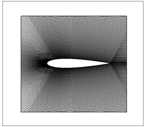 | Figure 1. Structured “C” type grid used for NACA0015 CFD simulation |
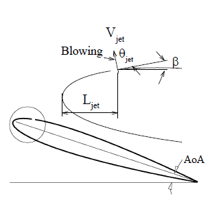 | Figure 2. Blowing control mechanism |
The grid shown is a “C” like structured grid. In order to resolve the boundary layer the mesh is refined on airfoil surface and over the blowing slots. The maximum aspect ratio of cells near the surface has been kept less than 50, and the first cell height has been fixed at 3*10-5 m (Y+≈1). Different size of grids are used to ensure grid independence of the calculated results until a stage is reached where the solution exhibits negligible change with further increase in the number of nodes. Consequently, the total number of cells is adopted as 180,000 cells.
2.2. Blowing Mechanism
As mentioned above blowing mechanism modeled as velocity inlet boundary condition and in this study we want to investigate three different jet angles (0º, 30º, 45º) and three velocity ratios (1, 2, 6), to obtain this, jet velocity defined as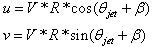 | (2) |
Where  is free stream velocity, R is jet velocity ratio and
  is the angle between the free stream velocity direction and the local jet surface,
  is the angle between the local jet surface and jet entrance velocity direction.
2.3. Governing Equations
In this review, because the Mach number is M ~ 0.05, the flow is incompressible. Also with regard to steady and two-dimensional condition governing equations will be as follows:
2.3.1. Continuity Equation
 | (3) |
Where and
and are velocities in x and y directions respectively.
2.3.2. Momentum Equation
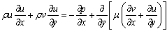 | (4) |
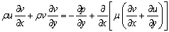 | (5) |
Where  is dynamic viscosity, andis pressure.
2.3.3. Turbulence Model
The viscous model used for modeling the turbulence is Spalart-Allmaras. This model is a one equation model for the turbulent viscosity. It solves a transport equation for the kinematic eddy (turbulent) viscosity . In its original form, the Spalart-Allmaras model is effectively a low-Reynolds number model and was designed specifically for aerospace applications involving wall-bounded flows and has been shown to give good results for boundary layers subjected to adverse pressure gradients.The turbulent viscosity is computed from
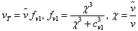 | (6) |
And the transport equation for  is
is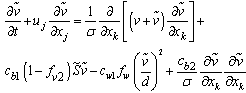 | (7) |
More details about this equation can be found on reference[23].
2.4. Flow Solver
The freely-available prediction code, XFOIL and the commercial code, FLUENT were used detailed calculations. The Spalart-Allmaras fully turbulent model was used for modeling turbulence. The FLUENT code solves the Reynolds averaged Navier–Stokes equations using finite volume discretization. Second order upwind discretization in space is used, and the resulting system of equations is then solved using the SIMPLEC coupled solution procedure until convergence criteria of O (5) reduction in all dependent variable residuals is satisfied. Velocity inlet boundary conditions are used in the upstream and outer boundaries. Pressure outlet boundary condition is used in downstream and No-slip boundary conditions are used at solid surfaces. Low free stream turbulence levels are used to match the wind tunnel characteristics. A free stream turbulence level of  = 0.1% is used.
3. Validating Results
 | Figure 3. Comparison of the NASA experiment data and present work computational data for NACA84-M (L=32.5%C, W=0.333%C) |
Meshandthecomputationalmethoddescribed abovewere usedto simulate NACA report no.385 first. Cause of using this report for validating the method is availability and comprehensiveness of its results.These results obtained over than 1200 different test condition which investigated the effect of parameters of the jet slot width, slot location, and air supply pressure inside the airfoil on aerodynamic properties of NACA84-Mairfoil, and has been published public.To ensurethat we can simulate blowing effects correctly, theexperimentwassimulatedin different conditions, and theresultscan be seeninFigure 3.Asseenin Figure 3, simulations show good agreement with experimental results and method is validated. Now we change the airfoil profile, and using the virtual wind tunnel createdto investigate blowing effects on NACA0015airfoil.
4. Results & Discussion
The purpose of these simulations is to study the effects of jet location, jet angle and blowing ratio on NACA0015 airfoil aerodynamic coefficients and separation. To this end, more than 160 simulations were performed and the effect of these parameters was investigated. Simulation results showed that with increasing angle of the jet relative to airfoil surface lift generated is also increasing. For example, when slot was in 10%C, blowing in angle 45º increasing the coefficient of lift to 3 times, but increasing the angle of jet significantly enhances the airfoil drag, sometimes up to 10 times of normal airfoil drag. Being able to simultaneously determine variations in lift and drag coefficients due to blowing the  ratio is used. The l/d Graph in Figure 4 is plotted for different angles of attack. As seen in the figure, the maximum amount of l/d ratios are for tangential states, so the best blowing angle is zero and next comparisons are done with the default tangential blowing.
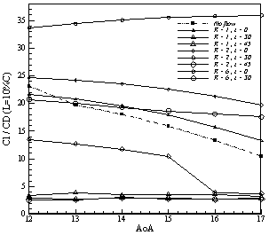 | Figure 4. Comparison between L/D ratios of different blowing angles |
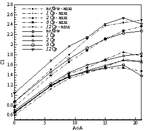
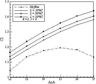
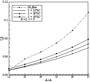
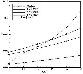
Comparing simulation results to determine the most effective location for blowing was found that whatever the slot location became close to the trailing edge of the airfoil larger amount of lift is produced, this is because the starting vortex is produced, is more powerful. But this trend is reversed for the drag coefficient. Whatever Jet became much closer to the leading edge it became more effective and more reduction in drag can be seen. This is because the blowing has covered more surfaces and changing the velocity profiles in the boundary layer over more length of airfoil. Change of velocity profiles prevent of formation strong transverse velocity gradients in the boundary layer and according to the Newton's law of stress with a uniform velocity distribution shear forces are smaller and thus less friction drag is produced.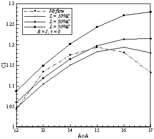 | Figure 5. Effects of jet ratio and location on lift coefficient |
 | Figure 6. Effects of jet ratio and location on drag coefficient |
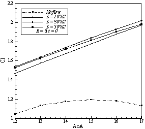
Simulations shows that increasing the jet velocity has an amplifying effect on lift generation mechanism, but increasing jet velocity ratios does not have a uniform effect on drag coefficient and it seems there is a critical value that if jet velocity exceeds, higher ratios make more drag. In Figures 5 to 10 effects of jet location and blowing ratio is shown. The maximum change in lift is obtained by blowing at 50%C and the ratio of 6, which caused 80% increase in the coefficient of lift on the angle of attack 17º. The maximum reduction in the drag also obtained by blowing at 10%C and ratio of 6, which reduces drag coefficient about 45 percent in 17º.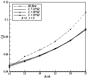 | Figure 7. Effects of jet ratio and location on lift coefficient |
 | Figure 8. Effects of jet ratio and location on drag coefficient |
 | Figure 9. Effects of jet ratio and location on lift coefficient |
 | Figure 10. Effects of jet ratio and location on drag coefficient |
Using blowing as a flow control method is an effective way to postponed separation over the upper side of airfoil. As the figures 5, 7 and 10 illustrate, applying blowing on the airfoil causes the stall angle to improve from 15º in the baseline case to higher angles of attack. Delaying separation upon the suction side of airfoil is an effective way to increase lift and decrease drag, because separation causes a significant loss of energy. Simulations show that by increasing the blowing ratio the separation point moves toward trailing edge. By increasing blowing ration higher amount of momentum injected to the retarded particles of boundary layerthat can't outcome any more against opposite pressure gradients.Figures 11 to 14 shows streamline about NACA0015 airfoil in angle of attack 15º. In figure 11 separation of streamlines in rear side of airfoil can be seen but in figure 12 this area became smaller (R=1) and in figures 13 and 14 we can see that separation area due to higher blowing ratios completely removed.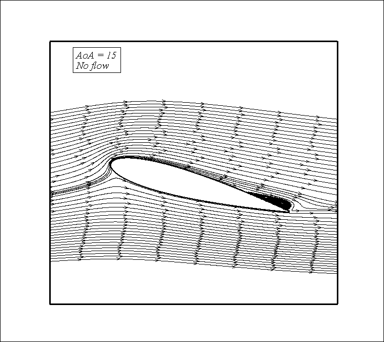 | Figure 11. Streamlines for no blowing case at AoA 15º |
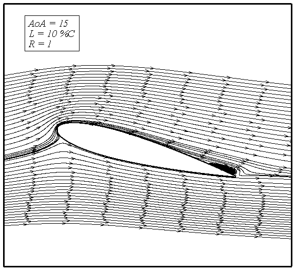 | Figure 12. Streamline for blowing at L=10%C, R=1 |
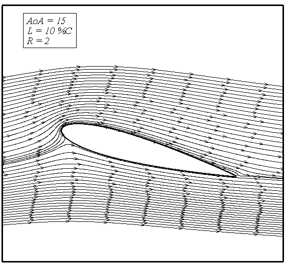 | Figure 13. Streamline for blowing at L=10%C, R=2 |
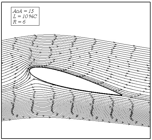 | Figure 14. Streamline for blowing at L=10%C, R=6 |
5. Conclusions
In this study the effect of steady blowing on a NACA0015 airfoil at different ratios and jet locations at AoA of near stall has been investigated. Results of the simulations are in good agreement with experimental results. Through the investigation, the best jet angle is tangential because by increasing jet angle drag increases dramatically. Comparing different cases of applying blowing show that when the jet location is near the trailing edge, the lift coefficient increases more effectively. But this trend is reversed for the drag coefficient. Whatever Jet became much closer to the leading edge itbecame more effective and more reduction in drag occurs.Simulations shows that increasing the jet velocity has an amplifying effect on lift generation mechanism, but increasing jet velocity ratios does not have a uniform effect on drag coefficient and it seems there is a critical value that if jet velocity exceeds, higher ratios make more drag. It was found that blowing has a significant effect on delaying separation on the upper side of the airfoil.
References
| [1] | Joslin, R.D. and D.N. Miller, Fundamentals and applications of modern flow control2009: American Institute of Aeronautics and Astronautics. |
| [2] | Anders, S.G., W.L. Sellers, and A. Washburn, Active flow control activities at NASA Langley. AIAA paper, 2004. 2623(2). |
| [3] | Miller, A.C., Flow control via synthetic jet actuation, 2004, Texas A&M University. |
| [4] | Carnarius, A., et al. Numerical study of the optimization of separation control. 2007. |
| [5] | Schetz, J.A., Foundations of Boundary layer theory for momentum, Heat, and Mass Transfer1984: Wiley Online Library. |
| [6] | Bamber, M.J. and N.L.R. Center, Wind-tunnel Tests on Airfoil Boundary Layer Control Using a Backward-opening Slot1932: National Advisory Committee for Aeronautics. |
| [7] | Poisson-Quinton, P.RecherchesTheoretiquesetExperimentalessur le Controle de la CoucheLimite. 1948. |
| [8] | Lachmann, G.V., Boundary layer and flow control: its principles and application. Vol. 2. 1961: Pergamon. |
| [9] | Gad-el-Hak, M., Flow control: passive, active, and reactive flow management2000: Cambridge Univ Pr. |
| [10] | Katz, Y., B. Nishri, and I. Wygnanski, The delay of turbulent boundary layer separation by oscillatory active control, 1989, DTIC Document. |
| [11] | Greenblatt, D. and I.J. Wygnanski, The control of flow separation by periodic excitation. Progress in Aerospace Sciences, 2000. 36(7): p. 487-545. |
| [12] | Wong, C. and K. Kontis, Flow control by spanwise blowing on a NACA 0012. Journal of aircraft, 2007. 44(1): p. 337-340. |
| [13] | Huang, L., et al., Numerical study of blowing and suction control mechanism on NACA0012 airfoil. Journal of aircraft, 2004. 41(5): p. 1005-1013. |
| [14] | Schatz, M. and F. Thiele, Numerical study of high-lift flow with separation control by periodic excitation. AIAA paper, 2001. 296: p. 2001. |
| [15] | Seifert, A., A. Darabi, and I.J. Wygnanski, Delay of airfoil stall by periodic excitation. Journal of aircraft, 1996. 33(4): p. 691-698. |
| [16] | Tinapp, F. and W. Nitsche. On active control of high-lift flow. 1999. |
| [17] | Wu, J., A. Vakili, and J. Wu, Review of the physics of enhancing vortex lift by unsteady excitation. Progress in Aerospace Sciences, 1991. 28(2): p. 73-131. |
| [18] | Wu, J.Z., et al., Post-stall flow control on an airfoil by local unsteady forcing. Journal of Fluid Mechanics, 1998. 371(1): p. 21-58. |
| [19] | Miranda, S., Active control of separated flow over a circular-arc airfoil, 2000, Citeseer. |
| [20] | Ekaterinaris, J.A., Prediction of active flow control performance on airfoils and wings. Aerospace science and technology, 2004. 8(5): p. 401-410. |
| [21] | Liu, Y., et al., Computational evaluation of the steady and pulsed jet effects on the performance of a circulation control wing section. AIAA paper, 2004. 56: p. 2004. |
| [22] | Dannenberg, R.E. and J.A. Weiberg, Section Characteristics of a 10.5-Percent-Thick Airfoil with Area Suction as Affected by Chordwise Distribution of Permeability, 1952, DTIC Document. |
| [23] | Spalart, P.R. and S.R. Allmaras, A one-equation turbulence model for aerodynamic flows. La rechercheaérospatiale, 1994. 1(1): p. 5-21. |
 Abstract
 Reference
 Full-Text PDF
 Full-Text HTML