-
Paper Information
- Paper Submission
-
Journal Information
- About This Journal
- Editorial Board
- Current Issue
- Archive
- Author Guidelines
- Contact Us
Advances in Computing
p-ISSN: 2163-2944 e-ISSN: 2163-2979
2014; 4(1): 6-9
doi:10.5923/j.ac.20140401.02
Features of Architecture Computer Aided Design Based on Modeling of Component Types
 Abstract
 Reference
 Full-Text PDF
 Full-text HTML
Mohammad Ali Mohammad Bani Youne
Head of the Department of Computer Information Systems, Ajloun National University, 21166, Irbid, Aidun, Jordan
Correspondence to: Mohammad Ali Mohammad Bani Youne, Head of the Department of Computer Information Systems, Ajloun National University, 21166, Irbid, Aidun, Jordan.
| Email: |  |
Copyright © 2012 Scientific & Academic Publishing. All Rights Reserved.
Computer Aided Design (CAD) is a very important field for many domains, especially industry. The complexity of designed objects coming from more than one system, and constraint of time of their introduction into production need to improve design automation and organization of the computer-aided design. A particular importance to the process of automated design issues is aggregation of design automation in one system. The problems of creation and reconfiguration architecture Computer Aided Design CAD and analyze results in order to reach solutions. In this paper, we introducea method of forming architectural CAD based on modeling of component types. The key issue for the solution of the organization of the design is to develop methods and tools to form Architecture CAD. The results indicate that established under the system reconfiguration subsystem CAD may be useful CAD developers in different stages of the life cycle of the system design.
Keywords: Computer Aided Design (CAD), Architecture design process, Resources CAD, CAD in Architecture
Cite this paper: Mohammad Ali Mohammad Bani Youne, Features of Architecture Computer Aided Design Based on Modeling of Component Types, Advances in Computing, Vol. 4 No. 1, 2014, pp. 6-9. doi: 10.5923/j.ac.20140401.02.
Article Outline
1. Introduction
- Computer Aided Design (CAD) can be defined as the use of computer systems to aid the creation, modification, analysis or optimization of design [1]. CAD can be used to produce computer animation and to design curves and figures in two or three dimensional space [2]. The computer systems consist of the hardware and software to perform the specialized design functions required by the particular user.The CAD software consists of computer programs to implement computer graphics on the system plus application programs to facilitate the engineering functions of the user’s company. CAD software is used to increase the productivity of the designer, improve the quality of design, improve communications through documentation, and to create a database for manufacturing [1]. The CAD hardware typically includes a computer, one or more graphic display terminals, a keyboards and other peripheral equipment. CAD output is often in the form of electronic files for print, machining, or other manufacturing operations. CAD can be used in many fields. Its use in electronic design, mechanical design Automation, it is also known as computer-aided design which describes the process of creating a technical drawing with the use of computer software [4]. Examples of these application programs include stress-strain analysis of components, dynamic response of mechanisms, heat transfer calculations and numerical control part programming. The collection of application programs will vary from one user firm to the other because their product lines, manufacturing processes and customer markets are different. These factors contribute to differences in CAD system requirement [4]. There are several different types of CAD, [5] each requiring the operator to think differently about how to use them and design their virtual components in a different manner for each [6]. The rest of this paper is organized as follows. Section 1 gives an introduction about computer aided design. In Section 2, the technical goals of the proposed method of forming architectural CAD based on modeling of component types is presented. Section 3 and 4 present the design phases and the procedure of forming the architecture of CAD. Finally, section 5 concludes the paper.
2. Technical Goals
- To form the architecture of CAD used empirical and formal methods and appropriate means, which are based on the knowledge base, expert opinions, analysis and simulations, logging, and testing technology. These models differ in complexity and cost tools for modelling, programming and experiments to determine the assessment characteristics, as well as the validity and reliability of the results. A common feature of most of these methods is there heuristic nature, due to the unsolved problems of synthesis of the structure of complex systems, and as a result, much of the subjectivity take place in the decisions taken by the system [7]. The main objective of the proposed method is to bring theoretical basis developed by the generalized model of the process and automated design system of formal rules. These rules provide conversion system model in working simulation models, which introduces a greater degree of objectivity in terms of preference for the decision to create architecture of CAD. For the study of complex systems, including CAD, simulation is widely used. The model is based on empirical or suspected data, 30 facts that are neither laws nor the laws and statistics forms of real or imagined events. In some cases, the new model allows us to identify patterns that did not see the analysis of known laws and initial data, due to their complexity, bulk, inconsistency or contradictions. Activities related to the initial stages of the technical proposal and schematic design provide analysis of the computer-aided design, identification of possible structures of CAD at subsystem level (for sub-component- level), the choice of rational options to design the feasibility study for CAD.
3. The Design Phases
- Let the system S has a finite set of system properties:
 ,
,  and having a numerical measure of generality. Let's possible (permissible) m of decomposition of S at
  decomposition method
  ,
,  where Lk - the number of subsystems in Sk - that of decomposition, each subsystem (component, resource) CAD RL characterized by a finite number of properties
  ,
,  , each of which has an individual numerical measure. Many properties of all resources in R at k-that decomposition
  ,
,  Interacting resources generate lots of system processes (project objectives)
  ,
,  . Then for each system property Qi there is a functional Vi of the processes occurring in the system
  . The problem of optimal organization of CAD is the selection, organization and resource allocation
  between project tasks Pk according to the set of the decomposing scheme k so as to provide the extreme values of the system properties extra Qk(S). Required to find the operating characteristics of CAD component download Pkj(t), which provides quality characteristics required for the design of objects in order to reduce design time and cost. Components (resources) CAD and their functional properties, and the relationship between them are controllable variables and is a measure of performance for optimization problem. Production program planning organizations units, features designed with CAD products (mainly their complexity) and the technological requirements of production are limited optimization problem. The specific CAD applications and allow and improve the reliability and validity of the choice of the system architecture. System model of the process is the structural basis of the initial description as long as it explores many functional characteristics of CAD, therefore, the structural components of the CAD model naturally grows out of a more general system model and the process of its production is reduced to the specification of the system operator model. This greatly simplifies the task of specific formation of an optimization problem, and reduces the search space of solutions and corresponding implementations. A problem persists at different organizational forms of CAD, and the solution is divided into a number of interrelated steps and tasks. The first stage of CAD, - preliminary design of the system is the main objective to determine the need of changes in the existing plant design technology and the identification of the purpose of creating and modification of CAD. Here are the tasks:1. Identifying gaps and "narrow", as critical places in the existing design technology.2. The formulation of the objective of the transition to a new technology design; Generate a description of the verbal and symbolic model is a viable option for Architecture.3. Pre-selection options architecture and creation of a set of the most promising options for further detailed analysis of each option. 4. Documenting the findings and recommendations from the results of research and preparation of a feasibility study of the implementation of new computer-aided design.Next, conduct a systematic evaluation and comparison of variants of architecture, formed in the first stage of CAD. Here, the following tasks:1. Building detailed resource-procedural functional models need variants analysis of architecture.2. Construction of empirical run-time design procedures on the complexity of the design and characteristics of the use of resources.3. Execution of the empirical relationships in the form of simulation models of the design processes.4. Build models of design procedures in the process model.5. Conducting simulations on models to obtain estimates of technical and economic parameters and operational characteristics of CAD.6. Techno-economic analysis of the information and the choice of the best option for the implementation architecture.The next stage involves the implementation of hardware and software, information and linguistic environment, which is also accompanied by a simulation model of the process in "Figure.1". These experiments were conducted as refine models to choose a virtual solution in the development of components of CAD alternatives.
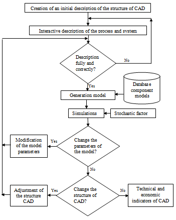 | Figure 1. A method of forming the architecture of CAD |
4. Method and Procedure
- Documents were created on the first two stages of CAD and they were used for testing and operation. During the operation of the system simulation models were used to determine the most effective strategies of its assets and the possible "narrow" places.The method of forming the architecture of CAD is based on procedures that incorporate the following basic steps:1. A description of computer-aided design environment, process, system and class design objects.2. Automatic conversion (translation) of this description in the process of macro-model-aided design.3. Statistical analysis of discrete-event model.4. An assessment of the properties of the obtained results and the choice of the preferred option.
5. Conclusions
- Most of the formatting CAD is increasingly being used in the fashion design industry. It has become an especially important technology within the scope of computer-aided technologies, with benefits such as low product development costs and a greatly shortened design cycle.CAD enables designers to layout and develop work on screen, print it out and save it for future editing, saving time on their drawings. A method of forming architectural CAD is proposed based on modeling of component types.This is to form the architecture of CAD system developed modeling CAD. The proposed method indicates that established under the system reconfiguration subsystem CAD may be useful CAD developers in different stages of the life cycle of the system design.