Aswath S1, Chinmaya Krishna Tilak1, Abhay Sengar2, Ganesha Udupa2
1Department of Electronics and Communication Engineering, Amrita Vishwa Vidyapeetham, Kollam-690525, Kerala, India
2Department of Mechanical Engineering, Amrita Vishwa Vidyapeetham, Kollam-690525, Kerala, India
Correspondence to: Ganesha Udupa, Department of Mechanical Engineering, Amrita Vishwa Vidyapeetham, Kollam-690525, Kerala, India.
| Email: |  |
Copyright © 2012 Scientific & Academic Publishing. All Rights Reserved.
Abstract
In this paper a control system is designed to operate a Humanoid Robot “Bioloid Premium” using DTMF (Dual-Tone-Multiple-Frequency) technology of mobile phones for long range operations. The mobile phone with the operator acts as a transmitter and the one attached to the Robot acts as a receiver and hence no additional communication devices are required. The operator calls the mobile installed in the humanoid Robot which gets activated through auto answering mode. In the course of a call, if any button is pressed, a DTMF tone corresponding to the button pressed is heard at the other end of the call. The Humanoid Robot perceives this DTMF tone with the help of the phone placed on it. The received tone is processed by the Arduino microcontroller with the help of DTMF decoder. The decoder decodes the DTMF tone into its equivalent binary digit and the same is sent to the microcontroller. The microcontroller is programmed to take a decision for any given input and outputs its decision to the CM-530 controller through a Zigbee wireless interface. The output decision of the CM-530 processor is sent to motor driver in order to control the servo motors in required direction for human like moves. Auto answering video calling is done in order to control the humanoid very easily and precisely. Experiment based on the DTMF has been carried out which can be implemented in the humanoid robot for various applications like security or safety, defence, assistance in medical and environmental hazards and other humanitarian services.
Keywords:
Humanoid Robot, DTMF, Microcontroller
Cite this paper: Aswath S, Chinmaya Krishna Tilak, Abhay Sengar, Ganesha Udupa, Design and Development of Mobile Operated Control System for Humanoid Robot, Advances in Computing, Vol. 3 No. 3, 2013, pp. 50-56. doi: 10.5923/j.ac.20130303.03.
1. Introduction
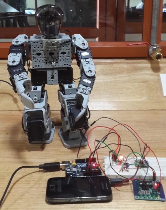
In the age of electronic systems it is important to be able to control and acquire information from everywhere. Although many methods to remotely control systems have been devised, the methods have the problems such as the need for special devices and software to control the system. Since analog devices are rapidly changing with digital devices, digital DTMF decoders become important. The DTMF is the signal generated by pressing an ordinary telephone's touch keys. In the United States and perhaps elsewhere, it's known as "Touchtone" phone (formerly a registered trademark of AT&T). Cable operators used DTMF technology to mark the start and end of commercial insertion points during breakdown of stations for companies benefit. Before the invention of a better technology in 1990, fast, unacknowledged and loud DTMF tone sequences were used for commercial breaks in cable channels in United States and elsewhere[1]. A concept of toy car controlled by DTMF was also developed which gives a solution to limited range control[2]. This paper extends the idea of the technology to control a more powerful device like humanoid robots to perform human like actions from large distances.Fig 1 shows the humanoid robot used in this paper.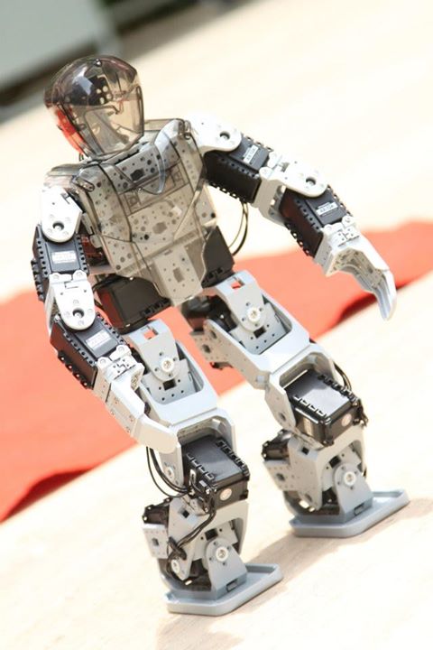 | Figure 1. Humanoid Robot |
Humanoid robots are being developed to perform human tasks like personal assistance, where they should be able to assist the sick and elderly. In essence, since they can use tools and operate equipment and vehicles designed for the human form, humanoids could theoretically perform any task a human being can, so long as they have the proper software. However, the complexity of doing so is deceptively great.
2. DTMF Technology
This paper suggests a method for control using the Dual Tone Multi Frequency (DTMF) tone generated when the user pushes mobile phone keypad buttons or when connected to a remote mobile system. Each key on your telephone's keypad has a unique frequency assigned to it. When any key is pressed on your telephone's keypad the circuit plays the corresponding DTMF tone and sends it to your local exchange for processing. DTMF tones can be imitated by using a White Box or Tone Dialler. It is also possible to record DTMF tones using a tape recorder or computer microphone and then played into the mouthpiece of your telephone to dial numbers. However if there is a significant amount of background sound behind the recorded DTMF tones, the tones may not work properly and cause problems when trying to dial numbers. Figure 2 shows the DTMF map for a 4X4 matrix keypad, the map shows each unique frequency which is assigned to each key on a standard 4X4 telephone keypad. This keypad has 4 more keys than a standard keypad (3X4-matrix). The keys A, B, C and D are not commonly used on standard home phone/fax, office phone or payphone.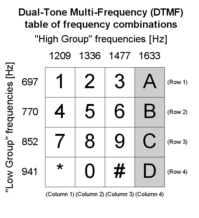 | Figure 2. The DTMF map for a 4X4-Matrix |
The contemporary mobile keypad is laid out in a 3x4 grid. When used to dial a telephone number, pressing a single key will produce a pitch consisting of two simultaneous pure tone sinusoidal frequencies. The row in which the key appears determines the frequency, and the column determines the high frequency. For example, pressing the key will result in a sound composed of both 697 Hz and 1209 Hz tone[2].
3. Circuit Design
The main components of this prototype are Arduino, 3G activated mobile phone, DTMF decoder (MT8870), Zigbee module and CM-530 controller. An MT8870 series DTMF decoder is used in this paper[3]. All types of the MT8870 series use digital counting techniques to detect and decode all the 16 DTMF tone pairs into a 4-bit code output. The built-in dial tone rejection circuit eliminates the need of pre-filtering. When the input signal given at pin 2(IN-) in single-ended input configuration is recognized to be effective, the correct 4-bit decode signal of the DTMF tone is transferred to (pin11) through (pin14) outputs. The pin11 to pin14 of DTMF decoder are connected to the pins of Arduino (Digital Pin 1 to Digital Pin 4)[4]. The pin configuration is shown in Fig.3.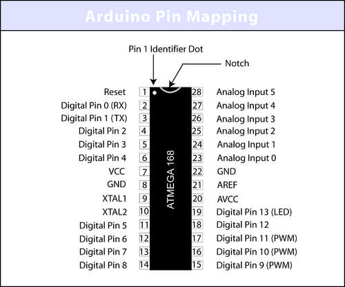 | Figure 3. Atmega168 Pin Mapping |
The Digital pin 5 to Digital pin 8 is set as OUTPUT. The outputs from Digital Pin 5 to Digital Pin 8 are fed to the Arduino Zigbee shield transmitter. The Arduino board is interfaced with the humanoid robot CM-530 controller via Zigbee wireless interface. Another Zigbee which is acting as the receiver is attached with the Humanoid controller. Every binary information sent from the Arduino is received at the humanoid controller through the Zigbee wireless interface. The humanoid robot is made-up of high torque (15 kgcm) 18 dynamixal servo motors, which are interconnected. The servo motors are arranged in such a pattern to resemble human like moves. These servos are controlled by the CM-530 controller. Based on the particular pattern of binary values received at the CM-530 controller the movements of servos is programmed in the required way for human like moves with the help of programming software Roboplus.[5] The Roboplus software has two components RoboPlus task and RoboPlus motion. The RoboPlus motion is GUI supported, which is used to create and modify robot’s motion data. The motion data is used in RoboPlus task to write the required program for the Humanoid Robot.Figure 4 is the circuit diagram of DTMF decoder. The DTMF tone from the mobile phone is fed to the DTMF decoder Pin no 2(-IN) through a headset jacket. The binary equivalent of the DTMF tone is transferred through the output pin 11 to pin 14 of the decoder. The output can be seen based on the LED glow.If the LED glows, that means the output through that pin is High (1) else the LED doesn’t glow, that means the output through that corresponding pin is Low (0). That is if the switch ‘2’ is pressed, the corresponding binary equivalent is ‘0010’, that is the LED on the pin 13 will glow, rest LED’s will be off. Fig.5 shows the experimental setup.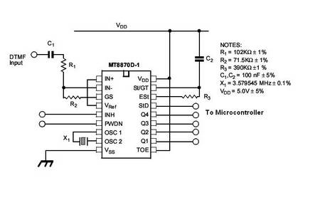 | Figure 4. DTMF Decoder Circuit Diagram |
 | Figure 5. Experimental setup |
4. Implementation of Control System
Figure 6. is the schematic of DTMF circuit interfaced with the controller on the humanoid. In order to activate the humanoid robot, a call need to be made to the mobile phone attached to the humanoid robot, from any mobile phone, which has DTMF and 3G video calling facility. The mobile phone in the humanoid bot is kept in ‘auto answer’ mode. So when a call is made, it automatically answers. Through the transmitter mobile in our hand, we can see whatever the mobile phone attached to the humanoid robot captures. Particular button may be pressed on the mobile phone for pre-defined desired action. If a button is pressed on the transmitter mobile, the corresponding DTMF tones thus produced are received by the mobile phone attached to the humanoid. When we press a key, for example 1, will generate a dual tone consisting of 697 Hz for the low group, and 1209 Hz of the high group.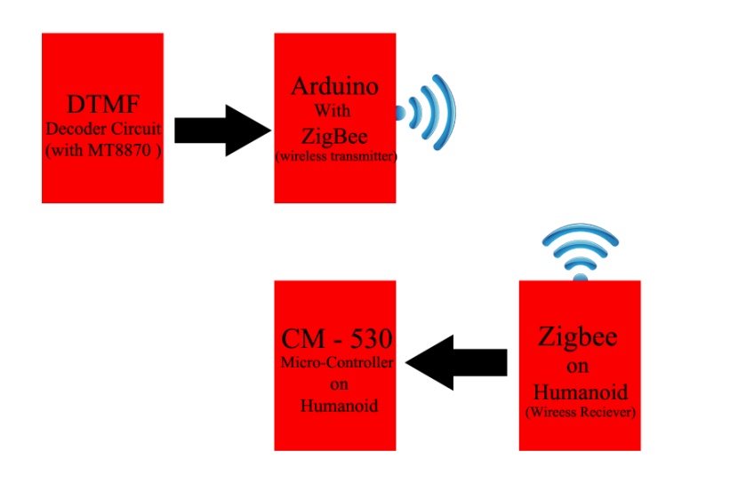 | Figure 6. Block Diagram of the complete control system |
The tone frequencies were selected such that harmonics and intermodulation products will not cause an unreliable signal. The decoder MT8870 have a digital low/high tone decoder with frequency pass band as in Fig. 7.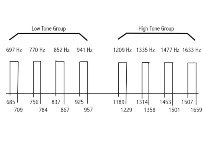 | Figure 7. Histograph of frequency pass band |
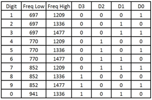
As the above frequency spectrum illustrates, each tone must fall within the proper band pass before a valid decode will take place. If one, or both tones falls outside the spectrum band pass, the decoder will operate erratic becoming unreliable or not operate at all.These tones are fed to MT8870 DTMF Decoder with the help of headset of the mobile phone. Once the DTMF signal has been applied, internal interfacing circuit must first separate the two tones into two discrete tones, one from the low group and other from the high group as shown in Figure 8. The separated signals are applied to two digital filters to decode the exact tone to corresponding binary value as shown in Table 1.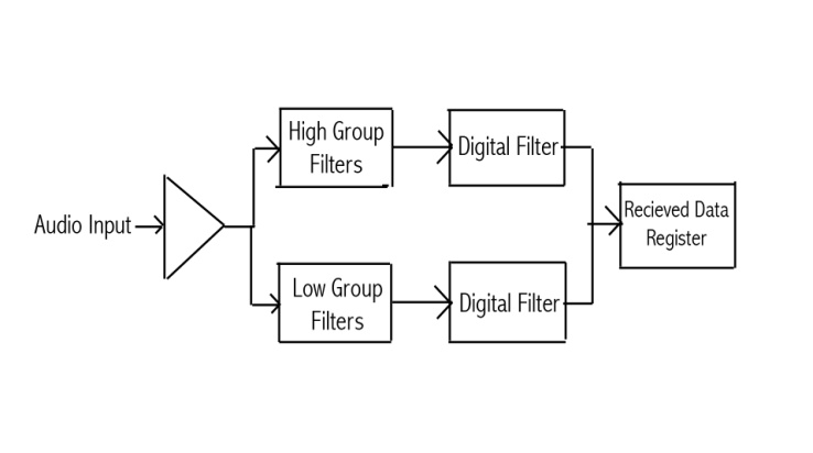 | Figure 8. MT8870 Decoder flow chart |
Table 1. Frequency Outputs of Decoder
 |
| |
|
Then the equivalent binary number is send to the Arduino Input pins. The Arduino output goes to RXD pin-6 on Zigbee (TXD). Zigbee transmitter sends the Arduino output to the Zigbee receiver connected to the CM-530. The Zigbee (receiver) send the received output to CM-530 through TXD pin2. The program preinstalled on the CM-530 processor is executed and the humanoid robot performs the required action. For example the Humanoid start moving forward when the number key ‘2’ is pressed in the mobile phone. Detailed conditions are shown in flow chart diagram Figure 9. 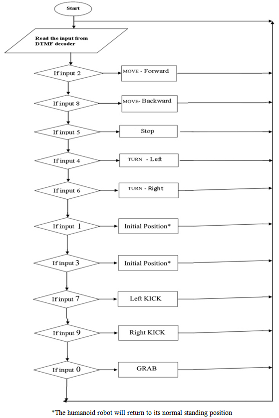 | Figure 9. Flow chart of the commands to Humanoid Robot |
Figure 10 shows the prototype of DTMF controlled humanoid Robot. The humanoid robot is made up of 18 high torque dynamixal servos (15kgcm). The receiver mobile is attached to the front portion and the rest circuitry is attached to the back of the robot. Based on the switches pressed from the caller end mobile and based on program in the CM-530 controller, the humanoid can perform certain task like walking, grabbing, kick etc.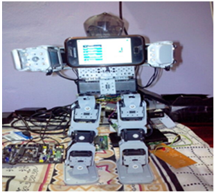 | Figure 10. Prototype of DTMF controlled Humanoid Robot |
The complete implementation of the control system from the caller’s mobile to the humanoid is shown in Figure 11.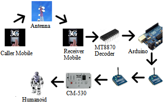 | Figure 11. Pictorial representation of the complete concept |
5. Results and Discussion
The process was implemented by making a call to a mobile connected to a DTMF decoding circuit. The corresponding communication signal between the two mobile phones is plotted on to MATLAB simulation software. The three cases indicating different actions of the Robot is achieved as given below. CASE (1) Pressing key-2 on the calling mobile moved the Humanoid robot forward.CASE (2) Pressing key-0 commanded the robot to pick up an object.CASE (3) Pressing the Key-8 on mobile phone signalled the robot to move back.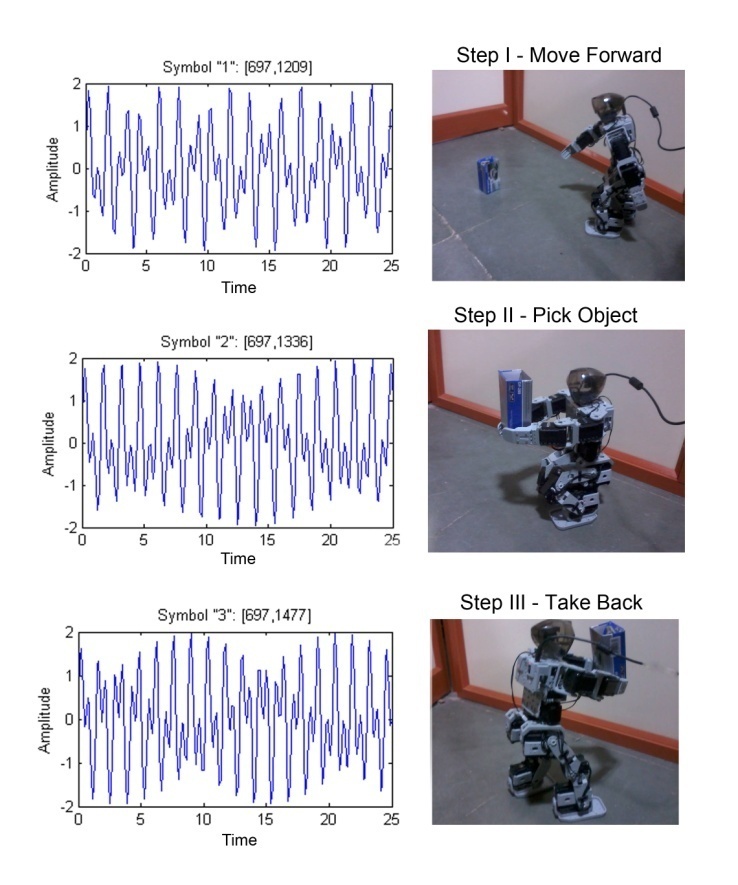 | Figure 12. DTMF tone signals and corresponding Humanoid action |
The graph for each keypad instruction is recorded as shown in Fig.12. It is seen that the frequency of signals are different for each actions. A variety of such commands are instructed to humanoid robot to perform a specific job like feeding a pet and helping the elderly. It is observed that the humanoid robot is capable of doing the pick and place actions without much delay and the performance is satisfactory.
6. Applications
DTMF controlled humanoids can update us with the current status of the security of the house. During a long vacation period, we can use this humanoid robot to feed the pet. We can locate the food and pet in home by the video data of the mobile camera and control the humanoid robot through the video call.Such robots can also be employed for defusing bombs. DTMF controlled humanoid robot can be used for oceanic surveillance wherein such robots can detect availability of certain minerals in deep water. DTMF usage can make it possible to program certain commands to the humanoid robot which can be triggered by the press of a keypad button and a series of actions can be controlled from any part of the world (when both the phones are under network coverage area.) Certain difficult tasks for the humans could be done easily using these humanoids. These Humanoids could be used for surveillance under 3G network.
7. Conclusions and Future Discussions
The mobile operated control system has been developed to communicate with the robot for the performance of various tasks. The robot performs pick and place task and the performance results are found to be satisfactory. The Humanoid Robot is controlled by the technology of transmitting DTMF tones between two mobile phones from any remote location in the world where mobile phone use is made available which rectifies the short range problem. The humanoid Robot can be controlled with much ease as video calling is done. Since the mobile phone at both the end act as transceiver. So, the control system does not require the construction of receiver and transmitter units. This model can be a very significant device in case of the information acquisition from the remote areas where direct interference of human being is quite impossible hence it would be a very useful topic to do further research on it.
ACKNOWLEDGEMENTS
The authors would like to thank Mechatronics and Intelligence Systems Research Lab, Department of Mechanical Engineering, Amrita University, Amritapuri campus for providing support to carry out the research and experiments.
References
| [1] | Siegmund M. Redl, Matthias K. Weber, Malcolm W. Oilphant, GSM and Personal Communications Handbook, Artech House Boston, London, 1998 . |
| [2] | Sabuj Das Gupta, Arman Riaz Ochi, Mohammad Sakib Hossain, Nahid Alam Siddique, Designing and Implementation of Mobile Operated Toy Car by DTMF, International Journal of Scientific and Research Publications, Vol 3, Issue 1, pp 1-7, 2013. |
| [3] | Online Available:www.natalnet.br/~aroca/afron/mt8870.pdf? |
| [4] | Online Available: http://www.arduino.cc/ |
| [5] | Online Available: http://www.robotis.com/xe/ |
 Abstract
 Reference
 Full-Text PDF
 Full-text HTML