-
Paper Information
- Paper Submission
-
Journal Information
- About This Journal
- Editorial Board
- Current Issue
- Archive
- Author Guidelines
- Contact Us
Advances in Computing
p-ISSN: 2163-2944 e-ISSN: 2163-2979
2013; 3(3): 36-49
doi:10.5923/j.ac.20130303.02
Distributed Data Storage on CubeSat Clusters
 Abstract
 Reference
 Full-Text PDF
 Full-text HTML
Obulapathi N Challa, Janise McNair
Electronics and Computer Engineering, University of Florida, Gainesville, Fl, 32608, U.S.A.
Correspondence to: Obulapathi N Challa, Electronics and Computer Engineering, University of Florida, Gainesville, Fl, 32608, U.S.A..
| Email: |  |
Copyright © 2012 Scientific & Academic Publishing. All Rights Reserved.
The CubeSat Distributed File System (CDFS) is built for storing large files on small satellite clusters in a distributed fashion to support distributed processing and communication. While satisfying the goals of scalability, reliability and performance, CDFS is designed for CubeSat clusters which communicate using wireless medium and have severe power and bandwidth constraints. CDFS has successfully met the scalability, performance and reliability goals while adhering to the constraints posed by harsh environment and resource constrained nodes. It is being used as a storage layer for distributed processing and distributed communication on CubeSat clusters. In this paper, we present the system architecture, file system design, several optimizations and report several performance measurements from our simulations.
Keywords: CubeSat Cluster, Distributed File System, Distributed Systems
Cite this paper: Obulapathi N Challa, Janise McNair, Distributed Data Storage on CubeSat Clusters, Advances in Computing, Vol. 3 No. 3, 2013, pp. 36-49. doi: 10.5923/j.ac.20130303.02.
Article Outline
1. Introduction
- There is a shift of paradigm in the space industry from monolithic one-of-a-kind, large instrument spacecraft to small and cheap spacecraft[1, 2, 3]. Space industry is moving towards faster, cheaper, and better small satellites which offer to accomplish more in less time, with less money. CubeSats have been embraced by Universities around the world, as a means of low cost space exploration and educational purposes[4]. CubeSat is a small satellite with dimensions of 10x10x10 cm3, volume of one litre, and weighs a kilogram. Owing to above stringent space and weight limitations, CubeSats have limited storage, processing and communication capabilities. As a result, a single CubeSat cannot accomplish much by itself. We need a group of CubeSats working together to perform non-trivial missions. Thus there is a need for distributed storage, processing and communication for CubeSat clusters. CubeSat MapReduce[5] addresses the problem of distributed processing for CubeSat clusters. It is based on MapReduce[6] from Google. CubeSat Torrent[7] explores torrent like distributed communications for CubeSat clusters. CubeSat Torrent is based on Torrent communication protocol[8]. However, to the best of our knowledge, the problem of distributed storage for CubeSat clusters has not been addressed yet. This paper addresses the distributed storage needs for CubeSat clusters while taking into account the salient, unique features and constraints of CubeSat clusters like wireless communication medium, link failures, stringent power and bandwidth constraints.Existing distributed file systems like Google File System (GFS)[9], Hadoop Distributed File System (HDFS)[10], Coda[11] and Lustre[12] are designed for distributed computer system connected using reliable wired communication medium. They are not well suited for data storage on CubeSat clusters for several reasons. They assume reliable communication medium. They are designed for systems where nodes are organised flat or hierarchically using racks for which, cost of communication is not very high. For CubeSat clusters, they result in high communication overhead, high control message overhead, consume lot of power and cannot work reliably on top of unreliable wireless network. We propose CubeSat Distributed File System (CDFS) to overcome the above mentioned problems.We have designed and implemented the CubeSat Distributed File System (CDFS) to store large files and facilitate large scale data processing and communications on CubeSat clusters. CDFS borrows the concepts of chunks and master-slave operation from Google File System (GFS)[9] and Hadoop Distributed File System (HDFS)[10]. CDFS is a scalable, reliable, power and bandwidth efficient distributed storage solution for CubeSat clusters. It is designed keeping in mind that underlying communication medium is unreliable and sometimes nodes are temporarily disconnected. For reliability, in case of data corruption or node failure, data is replicated on multiple nodes. In order to conserve bandwidth and energy, we propose a novel bandwidth and energy efficient replication mechanism called “copy-on-transmit”. In order to reduce control message overhead, we use tree based routing coupled with message aggregation.The major contributions of this work are a novel CubeSat cluster architecture, power and bandwidth efficient data replication mechanism called “Copy-on-transmit” and control message reduction using tree based routing and aggregation.
2. Related Work
- We surveyed some well known distributed file systems such as The Google File System (GFS)[9], Hadoop Distributed File System (HDFS)[10], Coda[11], Lustre[12] and TinyDB[13]. Design of GFS and HDFS is simple, fault tolerant and they are easy to scale. Hence, architecture of GFS and HDFS suits well for distributed storage of large files on CubeSat clusters. Below we present an overview of GFS and HDFS.
2.1. Overview of the Google File System
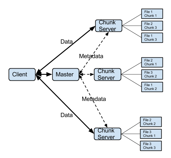 | Figure 2.1. Architectural overview of the Google File System |
2.2. Overview of Hadoop Distributed File System
- Hadoop Distributed File System (HDFS) is an open-source implementation of Google File System. Similar to GFS, HDFS supports write-once-read-many semantics on files. HDFS also uses master/slave architecture. Master node for HDFS is called NameNode. Slave node of HDFS is called DataNode. Role of NameNode is to coordinate the DataNodes. A HDFS cluster consists of NameNode and multiple DataNodes. NameNode manages the file system namespace and takes care of file access control by clients. The DataNodes stores the data. NameNode and DataNode typically run on Linux machine. HDFS is built using the Java language. Although HDFS programs can be written in wide array of programming languages including Java, C++, Python, Ruby, Perl, C#, Smalltalk, OCaml. When a file is written to HDFS, NameNode splits it into data blocks and distributes the data block to the DataNodes. NameNode manages metadata, file names, allocated data blocks for each file and the location of data block on DataNodes. Design and internal workings of HDFS are very similar to GFS. Detailed documents of HDFS can be found at their website[10].
2.3. Limitations of GFS and HDFS for CubeSat Clusters
- 1. GFS and HDFS are designed for computer clusters with flat structure and data centers which have hierarchical structure with nodes organized into racks and data centers. Contrasting to flat static topology, CubeSat clusters have very dynamic tree topology.2. Computers in data centers have unlimited supply of power. But, CubeSats have limited supply of power. Using GFS and HDFS for CubeSat clusters will lead to over power consumption.3. GFS and HDFS are designed for computer clusters which communicate using reliable wired medium. They cannot tolerate disruptions caused by unreliable wireless communication which is the basis of CubeSat clusters.4. Architecture of computers clusters and CubeSat clusters is different. As a result, GFS and HDFS designed and optimized for computers clusters will lead to lot of communication overhead for operations like data distribution, data replication.5. For the same reason, GFS and HDFS will result in high control message overhead for tree structures CubeSat clusters. Because of above limitations, GFS and HDFS are not well suited distributed data storage on CubeSat clusters. We designed CDFS addressing above problems and the design of CDFS is optimizes for CubeSat clusters. CDFS uses tree based routing which is optimized for routing messages on tree based CubeSat clusters. To reduce energy and bandwidth required for data distribution, CDFS uses a novel technique called “copy-on-transmit”. Using tree based routing and message aggregation, CDFS reduces control message overhead. CDFS uses weak consistency model and thus works with less overhead during temporary network failures.
3. System Architecture
3.1. CubeSat
- A CubeSat is a picosatellite with dimensions of 10x10x10 cm3, volume of one litre, and weighs less than one kilogram. CubeSats are built from commercial off-the-shelf components and are launched into low Earth orbits (LEO) using Poly-PicoSatellite Orbital Deployer (P-POD). CubeSats are currently designed for low Earth orbits and are suited well for applications involving distributed sensing (e.g., space weather). Approach of building CubeSats from commercial off the shelf components resulted in shorter development cycles and reduced costs, thus making CubeSats attractive to an audience beyond academia. However, stringent weight, power and geometry constraints severely limit processing, storage and communication capabilities of individual CubeSats. Below is a brief summary of the processing, memory, power and communication capabilities of CubeSats.1. Processing capabilities: Processing power of CubeSats is very limited. For low end CubeSats, processing power is about 25MIPS @ 25MHz[15]. Upcoming CubeSats have about 1000MIPS @ 1000MHz[16]. Considering these computational capabilities, processing large images on individual CubeSats would take about hours[5]. As a result, missions that require complicated image processing will incur hours of latency.2. Memory capabilities: CubeSat uses non-volatile memory like SRAM or DRAM for caching and non-persistent storage. Flash memory is used for persistent storage. For the CubeSats that have been launched till 2011, on chip SRAM is about 5 - 30KB and off chip RAM is about 256MB[5]. Upcoming CubeSats have RAM memory of about 1 GB and flash memory is 16 - 32 GB[16]. This is not a restriction and can be increased easily, by using higher density packaging chips with similar footprint meeting the space and weight constraints of CubeSat.3. Communication capabilities: CubeSat satellites in LEO have a very short communication window which is about 8 minutes on average[7]. This window occurs about 4 times per day per ground station. This gives a typical CubeSat and a ground station the opportunity to communicate for about 25 minutes per day at maximum[7]. Typical communication antenna styles include monopole, dipole and canted turnstile and the typical efficiency is about 25%. With the above constraints in place, and a limited data rate of 9600baud, downloading a single high resolution image of size about 100MB would take days[7]. This could be especially troublesome for imaging missions or missions whose success depends on amount of downlinked data.4. Power generation: A CubeSat typically generates about 2 W of power[7]. In addition, a significant amount of time is spent in eclipse, during which a CubeSat must rely on secondary storage device such as battery or supercapacitor. With communication system operating at about 500mW - 1000mW[7], this leaves an insufficient amount of power for the rest of the subsystems like thrusters which require about 1000mW. Power on CubeSats is very scarce resource and needs to be utilized very efficiently.A typical CubeSat has about 1GHz processing capability, 1GB RAM, few tens of GB flash memory[16], 1 Mbps CubeSat to CubeSat communication[17] and CubeSat to ground station communication data rate of 9.8 kbps[18, 19]. Processing and communication bottlenecks pose threat, especially to interplanetary missions and emerging missions like imaging, image processing, distributed weather and remote sensing, which needs large amounts of data communication and processing power. A single CubeSat will take days to months execute above non-trivial missions. One possible way is to unlock these missions is to use a cluster of CubeSats instead of a single CubeSat. Possibility of Earth observation using distributed system of small satellites has been explored in the paper Earth observation by distributed networks of small satellites[20]. Upon sensing, data can be distributed to the CubeSats in the cluster which can extract useful information using distributed processing and downlink it to ground station using distributed communication. CubeSat MapReduce[5] can help a cluster of CubeSats process data in a distributed fashion. CubeSat Torrent[7] can help a CubeSat cluster downlink data in a torrent fashion. CDFS aims to solve the unsolved problem of distributed storage for CubeSat clusters.
3.2. Network Architecture
- We proposed CubeSat Network architecture as shown in Figure 3.1. Proposed CubeSat Network consists of CubeSat Cluster and Ground Station Network. CubeSat cluster is composed of Master CubeSat and several Slave CubeSats. Ground Station Network is composed of Central Server and several Ground Stations. CubeSat cluster is a distributed system of CubeSats cooperating to achieve a joint goal without fixed absolute or relative positions. A typical CubeSat cluster has a radius of about 25km. Master will be located at the center of the cluster. Surrounding the Master node is the slave CubeSats. Master and slave CubeSats are connected using high speed communication links. CubeSats are connected to each other through reliable, directional, low power consuming and high speed links which are indicated by using solid lines. Connections between CubeSats and ground stations, depicted using dashed lines, are high power consuming, low speed and unreliable links. Each CubeSat is connected to a ground station and all ground stations are connected to a central server that issues commands and plays the role of data repository for the system.
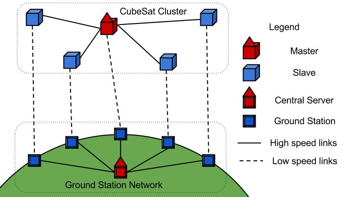 | Figure 3.1. Architecture of a CubeSat Network |
3.3. Roles of Master and Slave CubeSats
- 1. Sensor nodes: Master node is equipped with better processing, storage, communication and sensing hardware. It does sensing (take an image or do a radar scan) and generates huge amounts of data. This data is stored on the cluster using CDFS.2. Command center for CubeSats: Master node is the primary center for receiving commands from ground station and issuing commands to other CubeSats in the cluster.3. Metadata manager: Master node keeps track of all the metadata related to the mission including the list of participating nodes, their resource capabilities, map jobs, resource jobs and their status.4. Resource tracker and job scheduler: Master node keeps track of all the resources available in the cluster, their state and tracks available resources on each node. It is also responsible for taking job scheduling decisions like which job needs to be scheduled on which node and when.5. Role of slave nodes is limited to executing the processing and downlinking jobs assigned to it by the Master.
3.4. Roles of Central Server and Ground Stations
- 1. Command center for CubeSat Network: Central Server is the primary node for sending commands to CubeSat cluster.2. Data manager: Central server acts as the storage node for the downlinked data from CubeSat cluster.3. Ground Stations acts as a relay between CubeSats and Central Server. They downlink the data from CubeSat and send it to Central Server. They upload commands and data from Central Server to Slave CubeSats which forward them to Master CubeSat.
3.5. System Communication
3.5.1. Inter Cluster Communication
- CubeSats are connected to each other through a high speed (10Mbps) and low power consuming backbone network. High gain directed antennas like patch or LASER are used for inter cluster communication. There has been research on using tethers for low distance, high speed communication between satellites[21]. RelNav demonstrated a spacecraft subsystem[22] that will enable a flock of satellites. Space-based local area network[23] is another similar approach for space based local area networks. LASER based local communication networks have been explored as a part of FUNSAT V competition[24]. Communication and navigation subsystem demonstrated by RelNav also provides provide following services:1. 10Mbps inter-satellite communication link for data exchange between CubeSats.2. Relative position and orientation for formation flight.3. Cluster synchronization and timing for coordinated operations and coherent sensing.
3.5.2. Cluster to Ground Station Network Communication
- CubeSat geometry prohibits use of complex antennas[19]. As a result, CubeSats are connected to ground stations through simple antennas like monopole or dipole. Coupled with stringent power constraints and distances of order 600 - 800KM, this resulted in low speed links to connect to ground station. Typical CubeSat to ground station speed is about 1.2kbps - 9.6kbps[18] and AX.25[25] and CubeSat Space Protocol[26] are the major communication protocols used for CubeSat to ground station communication.
3.5.3. Inter Ground Station Network Communication
- Ground stations and Central Server are connected via the Internet. Internet provides a high speed (>10Mbps) and reliable wired communication medium between central server and ground stations. Power is not a constraint for the central server and ground stations, as they are connected to electrical grid.
4. CubeSat Distributed File System
- Data generated by satellite missions like imaging, distributed weather and remote sensing tends to be in the order of hundreds of megabytes. It is difficult to process or communicate all the data using a single CubeSat. One CubeSat takes about 5 hours to process[5] and several days to downlink[7] an image. However above mentioned missions can be speeded up by employing a cluster of CubeSats. Processing large amounts of data on CubeSat cluster can be speeded up by using CubeSat MapReduce[5]. Downlinking large amounts of data can be speeded up by using CubeSat Torrent[7]. However the problem of efficient data distribution on CubeSat clusters is not addressed yet. Existing distributed file systems does not work well with CubeSat clusters owing to their limitations explained in section 2.3 CubeSat Distributed File System (CDFS) aims to address the problem of data distribution on CubeSat clusters in a distributed fashion. This can facilitate wide array of distributed applications like distributed sensing, processing and communication. Here we will explain the design points which dictate the system design.
4.1. Key Design Points
- 1. Simple design: A typical CubeSat has about 1GHz processing capability, few tens of GBs of memory, 1GB RAM, 1Mbps inter cluster communication speed, 9.6Kbps communication capability and 1.5W power generation capability[7]. For CubeSats, processing, bandwidth and battery power are scarce resources. So the system design needs to be really simple.2. Low bandwidth operation: CubeSat network is built using long distance wireless links (10kms for inter cluster and 600kms for CubeSat to ground station). As a result the cost of communication is very high. Transmitting and receiving data over radio consumes about 1000 times more energy than processing the same amount of data on CubeSat. Data and control traffic needs to be reduced as much as possible. 3. Network partition tolerant: The underlying communication medium is wireless and the environment is space. High velocity of satellites in LEO (relative to ground stations) makes the satellite to ground station link failure very common. They keep breaking very frequently. Topology of CubeSat cluster is also very dynamic, causing the inter satellite links to keep breaking very frequently. Sometimes, nodes go into sleep mode to conserve power. All the above factors can cause frequent breaking of communication links. So, if a node is temporarily unreachable, system should not treat it as a node failure. System design should tolerant to temporary network partitions.4. Autonomous: Most of the time, individual CubeSats and the system are inaccessible to human operators. So the software design should take care of all failure scenarios. A reset mechanism, at node and network level, should be provided. In case if all the fault tolerance mechanisms fail, system will undergo reset mechanism and start working again. As a result, distributed file system should be able to operate completely autonomously without human intervention.5. Data Integrity: Memory failures are fatal for satellite missions. Even though memory chips for satellites are radiation hardened, high energy cosmic rays can sometimes cause trouble. For example, the Mars rover Curiosity had suffered a major setback because of damage to the memory of its primary computer caused by a high-energy particle. Hence, data integrity should not be violated.Along with the above design points that CDFS shares additional design points with GFS and HDFS which are highlighted below.1. Component failures are norm: Given large number of CubeSats and communication links, failures are norm rather than exception. Therefore, constant monitoring, error detection, fault tolerance, and automatic recovery must be integral to the system.2. Small number of large files: Files are huge by traditional standards. Images and remote sensing data generated by satellites tend to be in the order of hundreds of megabytes. 3. Immutable files and non-existent random read writes: Random writes within a file are practically non-existent. Once written, the files are only read, and often only sequentially. This kind of access patterns are common for imaging, remote sensing missions and programs like MapReduce that process this data and generate new data.CDFS has similar goals compared to GFS and HDFS namely, availability, performance, scalability and reliability. But, owing to its radically different operating environment, the system design points and constraints are very different for CDFS. GFS and HDFS were designed for non-power constrained cluster of computers connected using high speed wired media. CDFS is meant for distributed data storage on CubeSat clusters which use wireless communication medium for exchanging data and have severe power and bandwidth constraints. Design of CDFS should be simple, operate with very less bandwidth consumption and operate autonomously without requirement for human intervention. It should be tolerant to network partitions, temporary link failures, node failures and preserve the integrity of the data stored.
4.2. CDFS Architecture
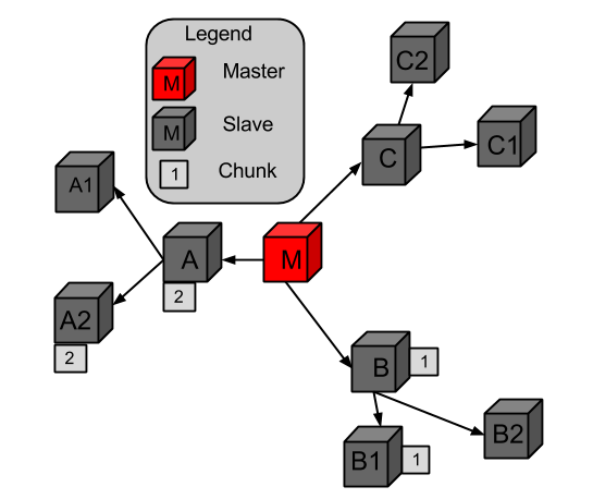 | Figure 4.1. CDFS Architecture |
4.3. File system Namespace
- CDFS supports a traditional hierarchical file organization in which a user or an application can create directories and store files inside them. The file system namespace hierarchy is similar to that of Linux file systems[27]. The root directory is “/” and is empty by default. One can create, rename, relocate, and remove files. CDFS supports hidden files and directories concept in a way similar to that of Linux file systems. Hidden file or directories start with “.” (period) and contain metadata (on Master), error detection and correction information (on Slaves), configuration information and other miscellaneous information required by CDFS. These hidden files are stored as normal files rather than distributed files, since these are very small and are used by the system locally. One can refer to the files stored on a server using notation: //server/filepath, where filepath looks like/directory1/directory2/ … /filename
4.4. Heartbeats
- Several problems can cause loss of data or connectivity between Master and slaves. In order to find out about the problems, Master node sends HeartBeat message to each of the slave nodes every 10 minutes once. Slaves reply with their status and problems, if any. Once the Master receives reply for heartbeat messages from all the slaves, it checks the messages to detect any problems and rectify them if possible. If a slave does not respond to the ping, Master will mark the node as temporary failure and will retry 2 more times with three minute interval between retries. If slave still does not respond, Master marks the slave as permanent failure. When a node is marked temporary failure, data chunks assigned to slave will not be replicated on other nodes, instead the secondary replica will be marked as primary. After permanent failure, Master node marks the node as dead and the chunks stored on that particular node are replicated to bring the replication factor back to two. When a node contacts the Master after recovering from permanent failure, node will be reset and all the data on the node will be erased.
5. File Operations
- CDFS has a simple interface. Its interface is similar to POSIX file system[14], but not POSIX file system compliant. CDFS supports file operations create, write, read and delete. Next section we describe in detail what happens when each of these operations is performed.
5.1. Create a File
- Once Master performs remote sensing operation (take an image or do a radar scan), it generates huge amounts of sensor data. Initially this data will be stored into a local file on the Master node. Typical size of this file is about 100 MB. Master stores this file on CubeSat cluster using CDFS to perform distributed processing or distributed downlinking. More actions will implement in sequence when a CDFS file is created by Master node. First is create (add a) file operation. It requires filename, file size, chunk size as parameters. By default, chunk size is 64kb and is optional. 1. Master calculates the number of chunks based on the file size and chunk size. (Number of chunks = file size / chunk size).2. Master generates chunk identifiers called chunk ids and assigns one to each chunk. Chunk id is an immutable id.3. Master assigns the chunks to slave nodes. Each chunk is assigned to one slave node in a round robin fashion. A copy of the chunk stored at this node which is called primary replica.4. Master stores the above metadata (filename, number of chunks, chunk to chunk id mapping and chunk id to slave node mapping) in its permanent storage and communicates the same to the backup Master.
5.2. Writing to a File
- Write operation is performed by Master node when it wants to copy a local file (on the Master) to CDFS. Files in CDFS are immutable. They can be written only once after that are created using create operation. Inputs for a writing a file are source filename on Master and the destination filename CDFS. Following actions happen in sequence when the Master writes a local file to a CDFS file.1. For each chunk Master performs the actions described in steps 2, 3, 4, and 5.2. Master looks up the metadata of the destination file on CDFS to find out the slave node responsible for storing the chunk. 3. Master determines transmission path (from Master to the slave node) using tree based routing algorithm. 4. From the nodes on the transmission path (excluding the Master and destination slave node), Master randomly picks a node to be the secondary replica of the chunk and notifies it.5. Master transmits the chunk to the primary replica node.6. While the chunk is being transmitted to the primary replica node, secondary replica node copies the chunk and stores in its local storage.7. After storing all the chunks on the cluster, Master commits the metadata to its memory and communicates the same to several other slave nodes.
5.3. Processing a File
- To perform MapReduce (distributed processing of large files) on a file stored on CDFS, the following sequence of operations is performed. More details about processing large files on CubeSat clusters are discussed in CubeSat MapReduce[5].1. Cluster administrator issues “process file command” to the central server.2. Using a relay ground station, server uplinks the command to the Master CubeSat.3. For each chunk of the file, Master sends “process chunk command” to the slave storing the chunk.4. Once the slave nodes process the chunks, results can be either downlinked to the server or it can be transmitted to the Master CubeSat. Then they can be merged to form the final solution and downlinked to the server. 5. If a particular slave is not reachable by the Master due to downtime or link failure, secondary replica of the chunk is contacted by the Master for processing the chunk.6. Once all the partial results or full result are received by the server, it sends an acknowledge message to the Master. 7. Lastly, the final file can be deleted or subjected to further analysis as required.
5.4. Downlinking a File
- These operations are performed when a file is downlinked. Downlinking a file is explained in more details in CubeSat Torrent[7]. 1. First, administrator issues downlink file command to Server.2. Server uplinks the command to the Master CubeSat.3. Then Master downlinks the metadata of the file to the Server.4. Master commands the slave CubeSats, storing the chunks of the file, to downlink the individual chunks.5. Slave CubeSats downlink the individual chunks to the Server.6. If a particular slave is not reachable by Master or ground stations, secondary replica node is contacted for downlinking the chunk.7. Once all the chunks are received by Server, it sends an ACK message to the Master. 8. Lastly, the file will be deleted as explained in the section 5.5.
5.5. Deleting a File
- The following actions are performed in sequence when a file is deleted.1. Administrator issues delete file command to the Server.2. Server uplinks the command to the Master CubeSat through a relay ground station.3. Master node looks up the metadata for the file and sends the delete chunk command to all the primary and secondary replicas nodes.4. Once a slave deletes the chunk, it sends ACK to the Master.5. Once the ACKs are received from all slave CubeSats, Master deletes the metadata for the particular file.6. Master CubeSat will send SUCCESS message to the Server through relay ground station.
6. Enhancements and Optimizations
- CDFS serves well as distributed data storage on CubeSat Clusters. However CubeSats have stringent energy constraints and CubeSat clusters have severe bandwidth constraints. So there is dire need to reduce energy and bandwidth consumption. Below we describe the methods we employ for reducing the energy and bandwidth consumption.
6.1. Bandwidth and Energy Efficient Replication
- To ensure reliability of data stored, CDFS uses redundancy. Each chunk has three replicas stored on three different nodes, called replica nodes. But, creating replicas is both energy and bandwidth consuming. For a CubeSat cluster both energy and bandwidth are precious. In order to reduce energy and bandwidth, Master node (Source node) can be used as the “Super Replica Node” (Super Replica Node: A node which stores the replicas of all chunks). Since the Master node performs sensing and has all the data initially, implicit replicas on Master node are created without any energy and bandwidth consumption. Using Master node as a Super Replica node essentially means that CDFS needs to create only two additional replicas. This also means that Master node should be equipped with sufficiently high storage to store all chunks. But this is a small cost compared energy and bandwidth saved. The data from source node is accessed only if other two replicas are not available, in order to conserve the power of source node.For additional two replicas, any random selection of slave nodes will do a good job for achieving reliability. But, if replica nodes are carefully selected, energy and bandwidth consumption can be significantly reduced. Consider the two scenarios A and B depicted in Figure 6.1: Bandwidth and Energy Efficient Replication. In scenario A, the chunk is replicated on nodes M (the Master node), A and B2. In scenario B, the chunk is replicated on nodes M, B and B1. The cost of communication (bandwidth and energy consumed) in first scenario is 3 times the average link communication cost (M -> A and M -> B -> B2). In second case, energy consumption is only 2 times the average link communication cost (M -> B -> B1). Storing a chunk on nodes that are on the same communication path or on nodes which are located close to each other yields best energy and bandwidth efficiency. Exploiting the above observation, we designed a novel method for providing reliability with low power and bandwidth consumption. This technique is called “Copy-on-transmit”.
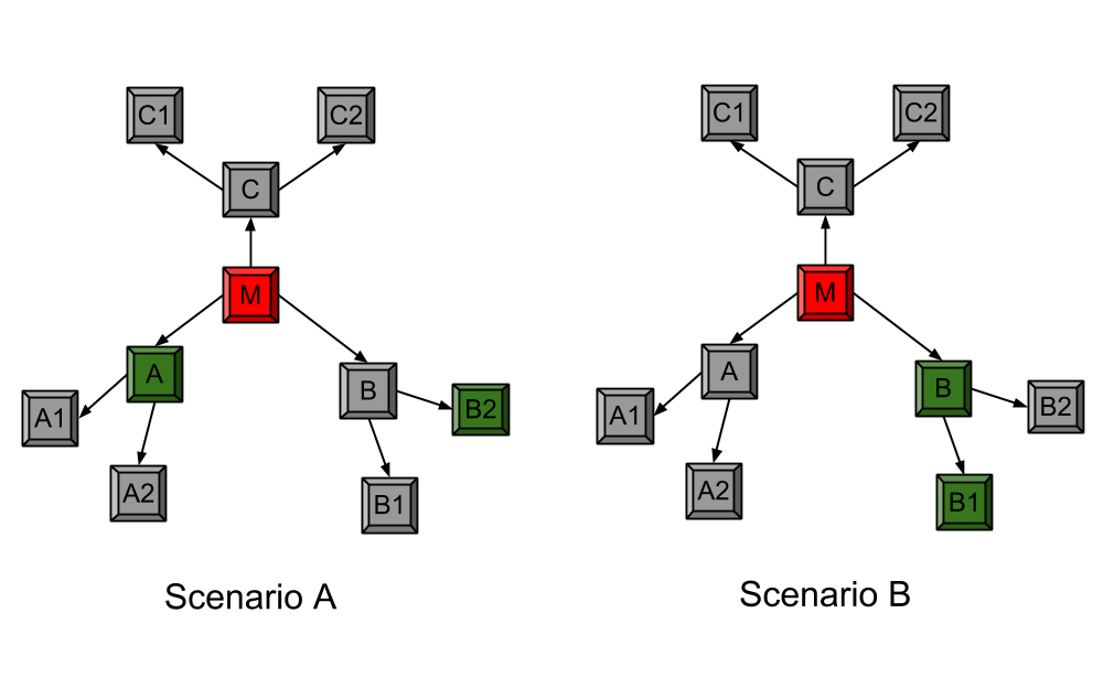 | Figure 6.1. Bandwidth and Energy Efficient Replication |
6.1.1. Case 1: Number of Nodes on Communication Path = Replication Factor (3)
- In this case, we replicate the chunk on all nodes along the path including the source and destination. When the chunk is being transmitted from Node M to Node Z through Node A, Node A makes a copy of the chunk and stores in its memory. Now the chunk has three replicas, one each at M, A and Z.
6.1.2. Case 2: Number of Nodes on Communication Path > Replication Factor
- In this case, we replicate the chunk on Master node M, destination node Z and a random on the path. When the chunk is being transmitted from Node M to Node Z through Nodes A, B, C, D, and E, Node C makes a copy of the chunk and stores it in its memory. Now the chunk has three replicas one each at M, C and Z.
6.1.3. Case 3: Number of Nodes on Communication Path < Replication Factor
- In this case, we replicate the data on all nodes on the communication path (Node M and Node Z) and some additional nodes. This scenario can have two different sub-scenarios (a) when the destination node is not a leaf node (has children) and (b) when the destination is a leaf node (no children). These two sub-scenarios are discussed as Case 3(a) and Case 3(b) below.
6.1.3.1. Case 3(a): Destination Node is not a Leaf Node
- In this case, first we replicate the data on all nodes (Node M and Node Z), along path. In order to meet the replication requirement, the communication path is extended beyond the destination node Z to store data on Node A. This ensures that there are required numbers of replicas.
6.1.3.2. Case 3(b): Destination Node is not a Leaf Node
- In this case, first we replicate the data on all nodes (Node M and Node Z), along path. In order to meet the replication requirement, one more replica of chunk needs to be created. Master randomly selects another node A and stores chunk on it, ensuring that there are required number of replicas.
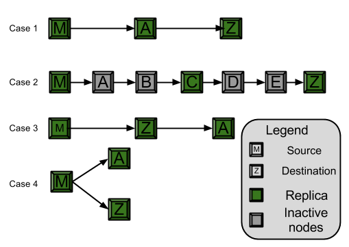 | Figure 6.2. Copy on transmit |
6.2. In Network Control Message Aggregation
- Control messages are used for chunk creation, deletion, downlinking and processing. They form a huge communication overhead. For a file with N chunks with a replication factor of R, a total of N * R network messages needs to be sent (one per chunk replica) for the above mentioned commands. Creating, deleting, downlinking or processing a file results in O(L * N * R) number of control messages at link layer and in proportion energy consumption, where L is the average number of hops between Master node and slave nodes in cluster. In order to reduce the overhead resulting from control messages, CDFS employs in network control message aggregation. As noted in the CDFS architecture, CDFS uses tree based routing [TinyDB] with Master as root. Master forwards the commands along the routing tree encompassing all slave nodes. As the nodes of the tree receive the command, they fork the command into sub-commands and forward sub-commands to its children. Forking of the command happens until it reaches all the leaf nodes. Once the leaf nodes receive command, they perform operations and forward the results to their parents. Parent nodes aggregate the results from its children and the results from itself and forward it to Master via its parent. It is similar to the aggregation mechanism used in TinyDB[13]. As an example, figure 6.3. shows how a delete command is disaggregated as it travels from Master to leaf nodes. Figure 6.4. shows how the results, the ACK messages in reply to delete command, are aggregated as they travel from leaf nodes to Master node. Tree based message routing with message aggregation requires only O(N) link later messages, instead of O(L * N * R) messages. As a result tree based routing with message aggregation results in significant bandwidth and energy savings.
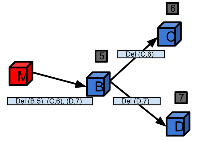 | Figure 6.3. Message disaggregation |
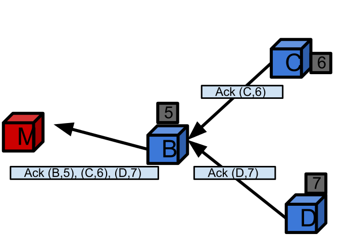 | Figure 6.4. Message aggregation |
6.3. Load Balancing
- The goal of load balancing is to distribute data to the nodes in the cluster in order to balance one or several of the criteria like storage, processing, communication, power consumption. When a file is created, number of chunks assigned to a slave node is proportional to the value of the LBF(node), where LBF is the load balancing function. Below we explain how we determine the load balancing function for uniform storage, proportional storage and several other criteria. Custom load balancing function can be used to perform load balancing according to users wish. However its needs to be noted that distributing data in order to perform uniform storage might result in uneven load balancing for processing or communication and vice versa. N is the total number of slave nodes in the cluster and LBF is the load balancing function. The following are the available load balancing functions available in CDFS:1. Uniform storage / processing / communications per node: LBF(node) = 1 / N2. In proportion to storage capacity of node: LBF(node) = Storage capacity of the node / Total storage capacity of the Cluster3. In proportion to processing capacity of node: LBF(node) = Processing power of node / Total processing power of the Cluster4. In proportion to communication capacity of node: LBF(node) = Communication speed of node / Total communication speed of the cluster.5. In proportion to power generation capacity of node: LBF(node) = Power generation capability of node / Total power generation capability of the cluster6. Hybrid: LBF(node) = a * LBF(node) for storage + b * LBF(node) for processing + c * LBF(node) for communication + d * LBF(node) for power, where a, b, c and d are normalized proportion coefficients and sum of a, b, c and d is 1.For missions that are processing intensive, it is desirable that number of chunks stored on a node is proportional to the nodes processing power. For communication intensive missions, it is desirable that number of chunks stored on a node is proportional to the communication capabilities of the node. For missions that are both processing and communication, hybrid function can be used. Additionally, in order not to overload nodes, a capping on number of chunks stored per node per file is suggested.
6.4. Chunk Size and Granularity
- By splitting files into large number of chunks, granularity will be improved. Small chunks ensure better storage balancing, especially for small files. However, as the number of chunks increases, so the amount of metadata, metadata operations and number of control messages which decreases the system performance. So, we select chunk size such that the ratio of number of chunks to number of slave nodes is about 100, with a 64Kb lower limit on chunk size.
7. Fault Tolerance
- CDFS is designed to be tolerant for temporary and permanent CubeSat failures and its performance degrades gracefully with component, machine or link failures. A CubeSat cluster can contain up to about a hundred CubeSats and are interconnected with roughly same number of high speed wireless links. Because of large number of components and harsh space environment, some CubeSats or wireless links may face intermittent problems and some may face fatal errors from which they cannot recover unless hard reset by ground station. Source of the problem can be in application, operating system, memory, connectors or networking. So failures should be treated as norm rather than an exception. In order to avoid system downtime or corruption of data, system should be designed to handle the failures and its performance should degrade gracefully with failures. Below we discuss how we handle these errors when they come up.
7.1. Master Failure
- Master node stores metadata, which consists of mapping between the files to chunks and chunks to slave nodes. If the Master node fails, the mission will fail. In order to avoid mission failure in case of Master failure, periodically metadata is written to Masters non-volatile memory, like flash, and the same is communicated to the shadow Masters. If the Master reboots because of a temporary failure, a new copy will be started from the last known state stored in Masters non-volatile memory. If the Master cannot recover from error within a certain period of time, a shadow Master presumes the role of Master. In case of failure of Master, slave nodes will ping the Master and shadow Masters periodically until a new Master presumes.
7.2. Slave Failure
- Using heartbeat messages, Master pings slaves periodically (every 10 minutes) to check their state. If a slave reports a fatal error, Master marks the slave node as failed. If a slave does not respond to the Masters ping, Master will retry 2 more times with three minute interval between retries. If slave still does not respond, Master marks the slave as failed. When a slave is marked failure, (in case of fatal error or slave not responding to Masters ping), the chunks stored on the failed node will be replicated. As a result, CDFS is resilient to slave failures.
7.3. Chunk Corruption
- Harsh space environment and the cosmic rays lead to frequent memory corruption. One of the computer systems of the Mars rover Curiosity had a memory problem due to high energy particles and resulted in a major setback for mission. Thus, ensuring the integrity of data stored on CDFS is of paramount important. CDFS uses checksum of data for detecting bad data. Performing data integrity operations on entire chunk is inefficient. If a chunk is found to be corrupt, discarding the whole chunk will lead to lot of wasted IO. It also requires lot of time and memory to read the whole chunk (64Kb), to verify its integrity. Thus, each chunk is split into blocks of 512 bytes. CDFS stores CRC of each block of data and performs checksum validation at block level. When a read operation is performed on a chunk, block by block is read and each block is verified for data integrity by comparing the stored checksum with newly computed checksum. This way if one of the blocks is found to be corrupt, only that block is marked bad and can be read from another healthy replica of the chunk. Employing data integrity check at block level ensures that partial input/output, computation or downlinking that was done before detecting the data corruption will not go waste. Doing data integrity at block levels also increases the availability of data.
7.4. Inter CubeSat Link Failure
- Owing to harsh space environment, communication links fail often. If a CubeSat to CubeSat link fails, the child node in the routing tree will retry connect to its parent. If the link re-establishment is not successful or the link quality is bad, the child node will ping its neighbours and search for a new parent node and joins the routing tree.
7.5. Network Partitioning
- Sometimes a single CubeSat or several CubeSats may get separated from the CubeSat cluster. We call this phenomenon network partitioning. In either case, the data stored on the separated nodes will be retained and will be available for downlinking to the ground stations. Once the Master node downlinks the metadata of the file to the central server, separated CubeSats can be contacted through ground stations for downlinking the data. Once the data is downlinked to the server, it will be deleted on the nodes.
8. Performance Analysis
- We simulated several remote sensing missions on CubeSat cluster. We used CubeNet simulator for performing simulations. CubeNet is a CubeSat network simulator developed at WAMs Laboratory at University of Florida[28]. Please refer to Figure 3.1 CubeSat Network Architecture and Figure 4.1 CDFS system architecture we used for these simulations. Below is the outline of the simulation experiments we performed.Administrator will issue a remote sensing command to central server. Central server will transmits the command to a relay ground station which will uplink it to the Master CubeSat. Upon receiving the command, Master CubeSat will perform remote sensing and obtain about 100MB of sensor data. Using CDFS, Master CubeSat distributes the sensor data to the slave nodes in the cluster. We measured variation in bandwidth and energy consumption, number of messages, and various other metrics. We varied the number of nodes in the cluster from 5 - 25. Each CubeSat has a processing, storage and communication capabilities of 1000MIPS @ 1000MHz, 1GB RAM, 64GB non-volatile memory, 10Mbps inter-cluster communication link and 9.6kbps ground station data rate. Below we present theoretical performance analysis as well as the results from our simulation experiments.
8.1. Number of Replicas
- Data reliability is achieved through replication. Each file is split into chunks and distributed to slave nodes. Each chunk is stored on multiple CubeSats, so that if some CubeSats fail, data is still available on other CubeSats. Number of replicas is primarily governed by required availability of data and node failure rate. Availability of a file (A) is given by,
 | (1) |
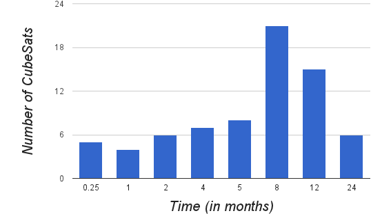 | Figure 8.1. Lifetime of CubeSats |
8.2. Chunk Size
- Chunk is the unit of storage and distribution of files on the slave nodes. By splitting files into small sized chunks, granularity will be improved. Small chunks ensure better storage, processing and communication balancing, especially for small files. But, fine granularity means, large number of small chunks. As the number of chunks increases, so will be the amount of metadata, metadata operations and number of control messages, leading to decrease in the system performance. On other hand, with coarse granularity, splitting files into small number of large chunks will lead to poor distribution of data which inturn leads to larger processing and downlinking times. For a file of size 100MB, Figure 8.2. shows the processing and downlink efficiency (actual processing or downlink speed / theoretical maximum), control traffic overhead percentage (control traffic / total traffic) for varying chunk sizes. Best processing and downlink efficiency is obtained for chunk size of 64Kb (log value of 6).
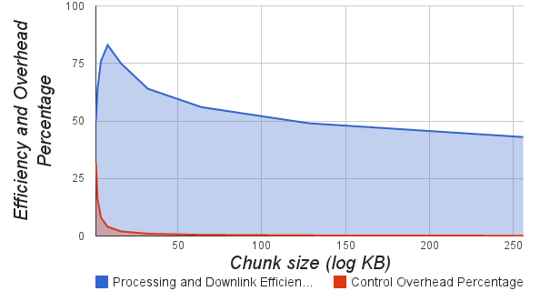 | Figure 8.2. Variation of processing and downlinking efficiency with Chunk Size |
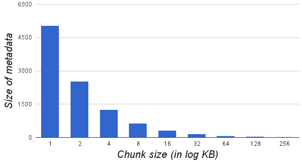 | Figure 8.3. Variation of metadata with Chunk Size |
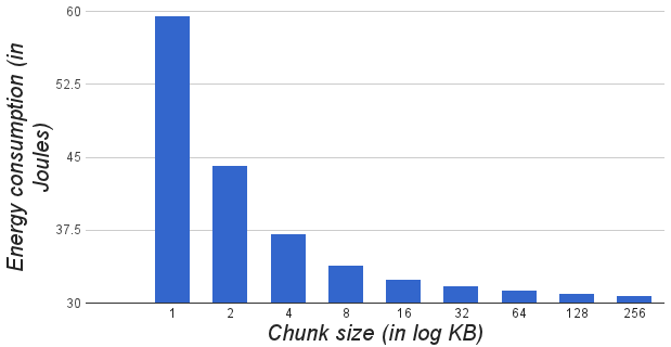 | Figure 8.4. Variation of network energy consumption with chunk size |
8.3. Master Node as the Super Replica Node
- Master node (Source node) does sensing and thus has all the sensor data to begin with. So, Master node can be used to store as a replica node for all the chunks. We can such a node (a node with replicas of all chunks) as “Super Replica Node”. With this mechanism in place, CDFS needs only two additional replicas on Slave nodes. In contrast, GFS[9] and HDFS[10] need three replicas. Super replica node can reduce energy and bandwidth consumption by about 35 - 40%. Figure 8.5. shows the time taken by CDFS and GFS (as well as HDFS) for writing a file of 100MB to the cluster. CDFS writes are about 50% faster than GFS and HDFS because of super replica node and reduced bandwidth requirements. However the memory size of the Master needs to be sufficient to store all the sensor data. But, this is a small price to pay for the energy and bandwidth savings that can be obtained from using Master node as super replica node.
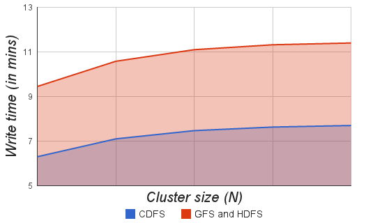 | Figure 8.5. Write times of CDSF and GFS (HDFS) |
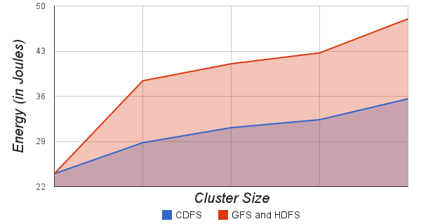 | Figure 8.6. Cluster Size vs. Energy consumption |
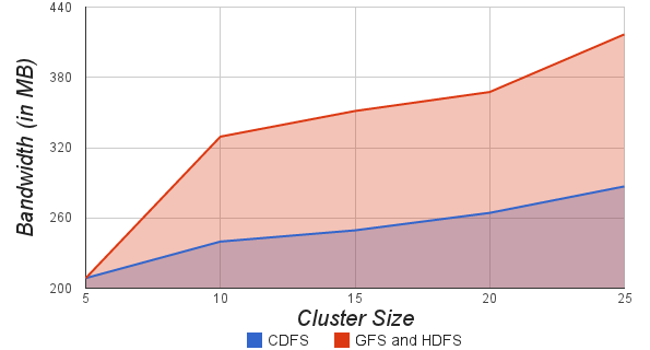 | Figure 8.7. Bandwidth consumption (in MB) vs Cluster size |
8.4. Copy on Transmit
- CDFS uses “Copy on transmit” to create replicas as explained in Section: 6.1 Energy and Bandwidth Efficient Replication. Figure 8.6. shows the energy consumption (in Joules) of a 25 node cluster for distributing a 100MB file. The red line shows the energy consumption for distributing file using GFS and HDFS (without “Copy on transmit”) and the blue line shows the energy consumption of CDFS (with Copy on transmit). Figure 8.7. shows bandwidth consumption for of a 25 node cluster for distributing a 100MB file. CDFS consumes about 10 - 45% less energy and bandwidth compared to GFS and HDFS. As a result, CDFS executes missions faster.
8.5. In Network Control Message Aggregation
- Control messages are aggregated using in network message aggregation as explained in “Section 6.2: In Network Control Message Aggregation”. Message aggregation greatly reduces the number of control messages and thus saves energy and bandwidth. For a file with C chunks with a replication factor of R, a total of C x R messages needs to be sent (one per chunk replica) for the above mentioned commands. And the same number of acknowledgement messages will be sent. Creating, deleting, downlinking or processing a file results in L x C x R number of control messages at link layer and in proportion energy consumption, where L is the average number of hops between Master node and slave nodes in cluster. Using message aggregation, Master needs to send only one aggregated message per node and each node in turn replies with one aggregated acknowledge message. It should be noted that an aggregated packet will be larger in size than non-aggregated packet. Figure 8.8. shows the variation of overhead bandwidth in KB for Create, Process, Downlink and Delete messages with Cluster Size in case of CDFS (with message aggregation) and GFS (without message aggregation). CDFS has about 60% less control traffic bandwidth and energy consumption compared to GFS and HDFS.
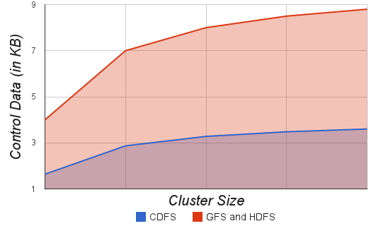 | Figure 8.8. Cluster Size vs. Overhead bandwidth |
8.6. Write Speed
- Master writes a file to the CubeSat cluster as described in Section 5.2: Writing to a file. First each file is split into chunks. Then chunks are transmitted to slave nodes. While the chunks are being transmitted, they are replicated on the fly. Figure 8.9. shows the maximum possible theoretical write speed and actual write speed for cluster sizes of 5 - 25 nodes for a file of 100 MB. Inter-cluster communication and slow writing of tail end chunks limit the efficiency of CDFS to about 80-90% of theoretical limit. Write speed is essentially independent of the cluster size, its mostly determined by the Masters cumulative communication speed.
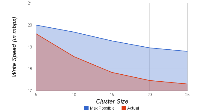 | Figure 8.9. Cluster Size vs. maximum possible write speed and actual write speed |
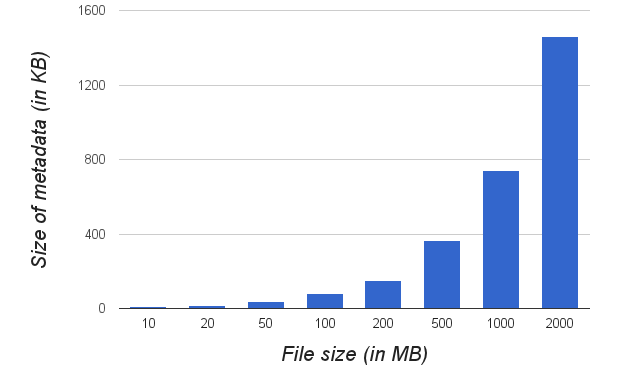
8.7. Metadata
- Metadata includes the mapping from files to chunks, and the location of these chunks on slaves, the namespace, access control information. Metadata overhead is very minimal (< 0.1 %) for large files (10Mb - 5 Gb) and the amount of metadata increases almost linearly with the file size (number of chunks). Size of metadata is independent of the number of nodes in the cluster. Figure 8.10. shows the variation of metadata with filesize. For a file of size 10 MB, the metadata is 8.3KB and for file of size 2GB, metadata in only 1.5MB (about 0.1%).
 | Figure 8.10. Size of metadata vs. Size of file |
8.8. Distributed Processing and Communication
- We ported CubeSat MapReduce and CubeSat Torrent to work on top of CDFS. Our simulation results indicate that CubeSat MapReduce and CubeSat Torrent on top of CDFS, with cluster sizes of 5, 15 and 25 CubeSats, can achieve speedups of 3.8, 12.9 and 22 times faster (compared to a single CubeSat) processing and downlinking of images and videos. These results indicate that CDFS can deliver high aggregate throughput to applications like MapReduce and Torrent and can support variety of distributed applications.
9. Conclusions and Future Work
- We have built CubeSat Distributed File System to store large files in distributed fashion and thus enable distributed applications like CubeSat MapReduce[5] and CubeSat Torrent[7] on CubeSat Clusters. It treats component and system failures as norm rather than exception and is optimized for processing satellite images and remote sensing which are huge by nature. CDFS provides fault tolerance by constant monitoring, replicating crucial data, and fast and automatic recovery. With backup Masters and redundant chunk replicas, CDFS design is fault tolerant.In CubeSat Clusters, network bandwidth and power are scarce resources. A number of optimizations in our system are therefore targeted at reducing the amount of data and control messages sent across the network. Copy-on-transmit enables making replicas without any additional or very little bandwidth or energy consumption. Message aggregation allows in network control message aggregation to reduce the network traffic. Failures are detected using HeartBeat mechanism. CDFS has built in load balancers for several use cases like CubeSat MapReduce and CubeSat Torrent and allows use of user defined custom load balancers. We simulated CDFS using CubeNet, a CubeSat network simulator. Even with individual CubeSat failure rate of 10%, the data is available 99.95% of the time. Optimal chunk size for faster processing and downlinking time is about 64Kb. Using Master node as super replica node saves about 30 - 40% bandwidth and in proportion energy. It also increases write speed by about 50%. Replication using Copy-on-transmit leads to 10 - 40 % savings in bandwidth and in proportion energy. Message aggregation helps CDFS outperform GFS with respect to Control message overhead by about 60%. Metadata overhead is very minimal (< 0.1 %) for large files (100Mb - 5Gb) and the amount of metadata increases almost linearly with the file size. CubeSat MapReduce and CubeSat Torrent on top of CDFS, with cluster sizes in range of 5 - 25 CubeSats, can achieve 3.5 - 22 times faster (compared to a single CubeSat) processing and downlinking of images and videos. These results indicate that CDFS can deliver high aggregate throughput to applications like MapReduce and Torrent and can support variety of distributed applications.Our future work will include emulating CDFS on a Raspberry Pi[30] Wireless Cluster and storing files using network coding to improve reliability and storage efficiency. We are also working on distributed remote sensing using CubeSat clusters.
ACKNOWLEDGEMENTS
- This work was supported by the NSF Division of Electrical, Communications and Cyber Systems (ECCS), Integrative, Hybrid and Complex Systems (IHCS) Program, Grant #0901706 and by the NSF Division of Industrial Innovation and Partnerships, Advanced Space Technologies Research and Engineering Center (ASTREC) I/UCRC Grant #0832517.