-
Paper Information
- Next Paper
- Paper Submission
-
Journal Information
- About This Journal
- Editorial Board
- Current Issue
- Archive
- Author Guidelines
- Contact Us
Advances in Computing
p-ISSN: 2163-2944 e-ISSN: 2163-2979
2012; 2(5): 66-75
doi: 10.5923/j.ac.20120205.01
A New Numerical Model to Analyze Stress Distribution of TMJ Disc from 2-D MRI Scans
 Abstract
 Reference
 Full-Text PDF
 Full-Text HTML
Yaser M. Alkhiary 1, Tamer M. Nassef 2, Inas A. Yassine 3, Seham B.Tayel 1, Abd ElSalam kh.Ezzat 1
1Prosthodontics department, King Abdulaziz University, Faculty of Dentistry. Jeddah, Saudi Arabia.
2Computer and Software Engineering, Misr University for Science and Technology (MUST), Giza, Egypt
3Systems and Biomedical Engineering, Cairo University, Giza, Egypt
Correspondence to: Tamer M. Nassef , Computer and Software Engineering, Misr University for Science and Technology (MUST), Giza, Egypt.
| Email: |  |
Copyright © 2012 Scientific & Academic Publishing. All Rights Reserved.
From the anatomical and biomechanical points of view, temporomandibular joint (TMJ) is sophisticated bicondylar articulatory complex with great demand on neuromuscular control with a frequency of motion indicated up to 2000 periods per day. This makes the TMJ one of the most frequently exerted joints of the human body and in conjunction with individual uniqueness of this joint places high demand on its design and reliability. Experimental studies concerning the distribution of the loads in the TMJ have been performed on animal models. Numerical modeling provides more understanding of joint physiology and pathogenesis of the joint diseases. Magnetic resonance imaging (MRI) has replaced computed tomography (CT) and arthrography as the primary modality in the evaluation of the TMJ. At this study a new numerical method are used to build 3-D model of TMJ from 2-D MRI scans and applied some stress-strain analysis to validate this model for different normal and abnormal patients. These models are based on multi-object reconstruction technique and tetrahedral elements building
Keywords: Finite Element Model, Temporomandibular Joint Stress Analysis, 3-D Reconstruction Modeling
Cite this paper: Yaser M. Alkhiary , Tamer M. Nassef , Inas A. Yassine , Seham B.Tayel , Abd ElSalam kh.Ezzat , "A New Numerical Model to Analyze Stress Distribution of TMJ Disc from 2-D MRI Scans", Advances in Computing, Vol. 2 No. 5, 2012, pp. 66-75. doi: 10.5923/j.ac.20120205.01.
Article Outline
1. Introduction
- Temporomandibular joint (TMJ) is one of the profusely operational joints in the body; its disorders are also quite common. It is an estimate that 20 to 25% of the population suffers from a temporomandibular disorder (TMD), whereas only 3 to 4% of sufferers get suitable treatment.[1] Commonly TMDs are caused by malfunctioning of the following parts of the TMJ: articular disc, articular cartilage, muscles at the joint, ligaments, teeth[18]. These may lead to TMDs like the pain dysfunction, Bruxism, arthritis or internal irregularities[2- 5]. The malfunctioning of the parts of the TMJ can be as follows: • Internal disarrangement of the articular disc causing it to slip out of its normal position in the joint capsule. • Wearing out of the articular disc due to continuous joint overloads, which might be due to clenching of teeth during sleep or teeth grinding, improper chewing pattern or excessive use of chewing gums. • Wearing out of the joint cartilage may be caused due to arthritis, fatigue in the muscles of mastication, ligament tear or irregularities in teeth alignment.[6] The TMJ is anatomically structured to withstand loading during mastication due to its mechanism of stress absorption and energy dissipation. The presence of the TMJ disc and articular cartilage is believed to prevent load concentrations. The cancellous bone of the mandibular condyle can resist compressive and tensile deformations during loading of the TMJ with minimum amount of bone mass due to its plate-like trabecular structure. The loading in the TMJ could stimulate remodeling, involving increased synthesis of the extracellular matrix.[7- 12] Experimental studies concerning the distribution of the loads in the TMJ have been performed on animal models. The number of such studies is limited, because it is difficult to implement experimental devices, such as strain gauges, into the joint and not to cause damage to its tissues without influencing their mechanical behavior. Mathematical models of the human masticatory system including the TMJ were found as a powerful tool to predict the loads acting on this joint. However, many studies have oversimplified the geometry of the TM disc. Therefore, the tissue deformations and the distribution of loads inside the joint could not be analyzed properly.[7] The finite element (FE) method has been largely used in dental biomechanics to understand the stresses and the deformations in the normal mandibles to simulate the motions of the TMJ components to analyze the stress distribution in the two discs and ligaments of each side during nonsymmetrical movements of a healthy joint to analyze the differences in the stress distribution of the TMJ between subjects with and without internal derangement and so on. The FE method has been proven to be a useful tool for evaluating the mechanical quantities of TMJ. The biomechanical environment in the TMJ is a key to understand the origin and progression oftemporomandibular disorders, so the reasonable modeling is also useful for clinical practice.[13-18].Magnetic resonance imaging (MRI) has replaced computed tomography (CT) and arthrography as the primary modality in the evaluation of the TMJ. Direct visualization of the disk afforded by MRI is a distinct advantage over arthrography.[19] Despite the superior resolution of CT and limited visualization of cortical bone by MRI, most osseous pathology is accurately depicted.[20] Intra-articular abnormalities are readily visible on MRI images, providing further information not available with other imaging modalities.[21]A small surface coil is placed over the TMJ; a bilateral examination can be performed with coupled coils. Images are obtained in the open-and closed-mouth positions to assess the position and reducibility (or recapture) of the articular disk. This is facilitated by placing a specialized device in the patient's mouth to keep it open and by instructing the patient to bite down on it for the closed-mouth views. From axial localizing images; sagittal and coronal planes are prescribed. Imaging is most commonly performed in these planes in order to document the position of the disk. Oblique sagittal and coronal images can be oriented to the condyle, but are unnecessary to demonstrate internal derangements.T1-weighted sagittal images are the cornerstone of the TMJ examination; the anatomy is clearly depicted, and the imaging plane is optimal for assessing articular disk position and for visualization of osseous and disc tissues, T2-weighted images are useful for detecting degenerative periarticular changes and the presence of a joint effusion. [22] Fat saturation or inversion recovery renders these findings more conspicuous. Gradient-echo techniques have been implemented to obtain cine-loop motion studies. Three-dimensional volume acquisitions allow a volume of tissue to be imaged rapidly and subsequently viewed in any plane. The use of intra-articular and intravenous gadolinium may provide utility in certain clinical instances for instance, the inflamed synovium or an inflamed arthropathy will avidly enhance after the administration of intravenous gadolinium.[23-25] Hence the aim of this study was conducted to analyze the stress distribution patterns in the disc displacement, of the human TMJ from MRI with and without wearing of anterior repositioning splint and the ability of the splint to reduce disc displacement when the muscle loads are applied. A finite element technique was used to achieve this purpose. The goals of this technique are, first the development of a new finite element model of a human TMJ from 2-D images and the surrounding bone, and second is to analyze the stress/strain patterns developed in the TMJ when the physiological loads are applied and compare to human models of TMJ. The first goal is comprised of two stages: the first stage develops a solid model from a MRI scan and the second stage creates a finite element mesh using this solid model and assigns suitable materials to this mesh. The second goal involves selecting relevant loads and boundary conditions. The final step is to obtain the stress/strain patterns within the TMJ by using a suitable force scenario and then compare those patterns with those obtained from human models. This finite element model of the TMJ will predict the stresses that help clinicians to understand how the TMJ behaves for a particular loading condition. So that in turn, they can develop a better clinical treatment for the TMJ disorders.
2. Materials and Methods
- This study included ten patients with symptoms of TMJ pain, joint noises, limitation of jaw opening, tenderness located in the articular region. Their age ranged between 25-45 years. All the patients, selected, were partially edentulous with bilateral missing of posterior teeth. They underwent a complete history, clinical examination, and diagnostic MRI. The clinical diagnosis was based on the presence of clicking on auscultation, tenderness of the lateral or posterior aspect of the TMJ and local pain associated with mandibular movement directly to the TMJ. Prosthetic construction: For all the patients clear hard acrylic mandibular anterior repositioning splint was constructed. The splint was tried in the patient's mouth while closing in the forward position. All adjustments were performed with simultaneous contact in the stabilized forward position was obtained. The patients were instructed to wear the appliance continuously for two months. They were allowed to discontinue only during brushing their teeth and during meal. The patients were seen at weekly intervals for necessary adjustment of the splint [26].
2.1. Magnetic Resonance Image
- MRI was performed without insertion of disc repositioning appliance. The scanning was done for both right and left joint for confirming the presence of displaced disc .It was made with 1.5 Telsa MRI systems with TMJ surface coil 6.0cm in diameter (MRI, Philips Gyroscan). The scan parameter was adapted for every patient to fulfill the best spatial resolution for the image (TE 20, TR450, and FOV 130/1.7).The degree of disc displacement was classified as follow: Less than half the disc displaced anteriorly to the anterior turbercle of glenoid fossa (grade I), All the disc displaced (grade III), Less than full disc displacement (grade II). The scanning was done for both right and left joint in closed - open mouth position. Then MRI and rescanning was performed after the two months of insertion of mandibular repositioning appliance with jaw in the splinted position and in opened positing for both right and left joint. The success of treatment method was assessed according to the criteria of disc capture, mentioned by Kurita et al[26]. Complete disc capture, partial disc capture, and no disc capture which is analyzed and confirmed by FE model.
2.2. Finite Element Study
- Any finite element study needs five basic inputs to accomplish the analysis.[27] These are the geometry, mesh, material properties, loads and boundary conditions. The model used in this study based on the MR images from displaced disc and after capture by anterior repositioning mandibular splint to study the distribution of stresses in complete capture, partial capture and in no capture.
2.2.1. Geometry Creation
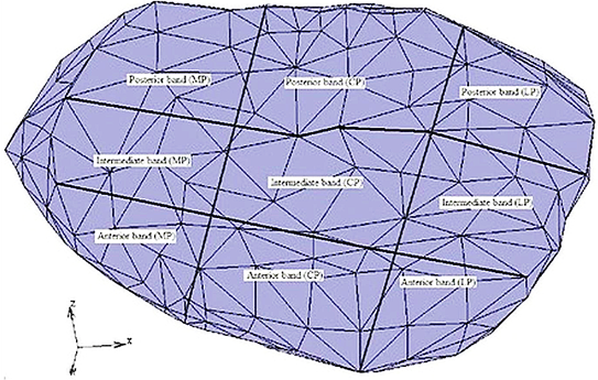
- For the 2-D MRI that used, the image scanned to evaluate the contour of the TMJ disc and their contacts as shown at Figure 1 by segment the image to different zones and eliminate the undesired regions and then the all contours are assembled to calculate the 3-D model.As the TMJ is comprised of the temporal bone, articular cartilage, articular disc, ligaments and the mandible arranged as shown in Figure 1, where: 1-Anterior band of articular disc, 2-Articular disc, 3-Articular tubercle (eminence), 4-Glenoid fossa, 5-Inferior joint space, 6-Intermediate (central) thin zone, 7-Lateral pterygoid muscle raphe, 8-Lower head of lateral pterygoid muscle, 9-Mandibular condyle (head), 10-Mandibular condyle articulating surface, 11-Mandibular condyle marrow, 12-Posterior band of articular disc, 13-Posterior disc attachment, 14-Superior joint space, 15-Upper head of lateral pterygoid muscle. In this study, assuming symmetry between the right and left TMJs only the left TMJ of a human was modeled. The current model includes the mandible, the articular disc, the surrounding part of the temporal bone and the ligaments.[28, 29] The articular cartilage was ignored in the current model. The geometry of the disc was created manually from the surface models of the mandible and part of the temporal bone. The articulating surface of the mandibular condyle was extracted from its surface model as shown in Figure 2 (A), using Dicomesher (1). This surface formed the lower surface of the articulating disc. The articulating surface of the temporal bone shown in Figure 2 (B) was extracted similarly to the mandible. After extracting the surfaces for the lower and upper region, the next step was to combine the two surfaces in a single model as shown in Figure 2(C) and connect them. Both the extracted surfaces were imported into one file. The medial, lateral, anterior and posterior geometry was approximated[9] by manually generating elements to connect the two surfaces and form closed surface defining the disc, as shown in Figure 2 (D).The articular disc is not of uniform thickness, as was the case here. The disc thickness varied as we moved from anterior to posterior and lateral to medial directions. The disc was thinnest in the intermediate zone where its thickness was 0.25 cm. It was thickest in the posterior region where its thickness was 0.63 cm. The thickness in the anterior part was 0.42 cm. To complete the TMJ geometry, the final addition was the ligaments. In this study, the posterior retrodiscal ligaments both superior and inferior[29, 6] and the TMJ ligaments[15, 16] were included, as shown in Figure 3.The ligaments were added to the model after the solid meshes of the bones and the disc were generated and combined. The ligaments were introduced as linear springs. The node to node spring connections were used, as shown in Figure 4. Nodes for the insertion and origin of ligaments were picked according to Almora[31] and visual inspection of human TMJ models.
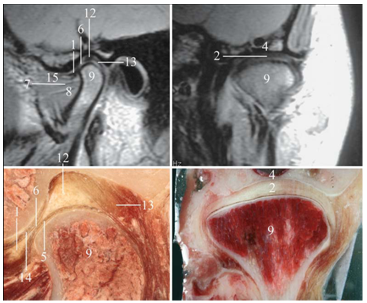 | Figure 1. MRI and autopsy midcondyle anatomy of normal temporomandibular joint: upper left oblique sagittal MRI, upper right oblique coronal MRI, lower left oblique sagittal section, lower right oblique coronal section (Maxillofacial Imaging.2006[28] |
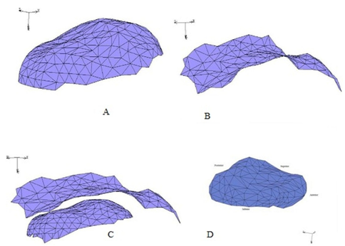 | Figure 2. (A) The mandible surface extracted from the surface model of mandible. (B) The temporal surface extracted from the surface model of the temporal bone. (C) The mandible and the temporal bone surface together create the surfaces of the disc model and (D) The solid model of the articular disc |
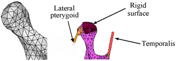 | Figure 3. (A) Retrodiscal Ligaments superior and inferior (B) TMJ Ligaments |
2.2.2. Mesh Process
- As the surface models of the mandible, the temporal bone and articular disc were ready, the next step was to generate 3-D solid meshes of them and combine them into one model. For this purpose surface models of each of the three entities were imported as (STL: surface tessellation of bone components). Meshing divides an entity into a finite number of small elements.[29] In solid meshing the hollow solid is meshed internally to form a solid mesh. Solid meshing was done using the Patran tetrahedral meshing provided. Patran tetrahedral meshing preserved the triangles of the surface mesh while the solid mesh was generated.[32] The solid mesh developed contained 4 nodes tetrahedral elements as shown in Table 1. To generate the mandible solid mesh, the mandible surface model was imported. Then this surface model was checked for presence of any cross elements and inside out elements. The overlapping elements are referred as cross elements and the elements a having surface normal directing inwards to the solid are referred to as inside out elements.[33] Then, using the sweep command the nodes within a distance of 0.001 cm from each other were combined as one node, to form the closed surface so that solid meshing can be done. Sweeping these nodes also helps to remove cross elements. After these checks on the surface model, the Patran tetrahedral meshing was invoked and a solid mesh of the mandible was generated with 4 nodes tetrahedral elements.
2.2.3. Material Properties
- The material properties of the articular disc were considered to be linear elastic. In the enhanced model, a non-linear material model defined the articular disc as Mooney-Rivlin solid. The disc was considered to be homogenous and isotropic for both the early as well as the enhanced model. The mandible and the temporal bone were considered to be linear elastic for both the early and enhanced models.[9, 14, 28, and 34] Linear material model the linear material properties are given in Table 2.The material properties were assigned to the individual solid meshes of the articular disc, the mandible and the temporal bone using material properties option, where E is the elastic modulus specified in MPa, and s for the Poisson’s ratio and k for the spring stiffness. Source column indicated the original source from where these values have been taken.
2.2.4. Loads and Boundary Conditions
- There are two loading conditions used in the literature for TMJ finite element simulations. The first uses condylar displacement and second uses muscle forces. This study uses muscle forces as point loads for loading the joint. The primary muscles of mastication are the masseter, the lateral and medial pterygoid and the temporalis[35-38]. The magnitudes of the muscle forces are obtained from Herring in which she reports the maximum possible muscle tension for each muscle[39]. Herring first calculated the cross sectional area of each muscle. The maximum muscle force was taken as being directly proportional to the cross sectional area of the muscle. Herring used the constant value of 40 N/cm2 to calculate the maximum possible muscle tension for each one and the inclination of these muscle forces. The inclination is the angle between the lines of action of the muscle forces and the occlusal (bite) plane. The line of action for each muscle was obtained by tracing their respective points of insertion and origin. The angles were measured from the right lateral direction, in an anticlockwise sense by a protractor.[39, 40] Herring reports that the accuracy of these measurements is within 5%. The details about the muscle forces are mentioned in Table 3. Position of the muscle forces are given as the x, y, z coordinates of the node referred as node id. The magnitude of force is given in Newtons. Inclinations are the angles made by the muscle force vectors with the occlusal plane. In the last column the x, y, z components of muscles forces is specified.
2.2.5. Contact
- As discussed earlier, there are two contact regions in the TMJ. The first contact region is between the TMJ disc and the surface of the temporal bone and the second region is between the TMJ disc and the mandibular condyle surface.[23] The contact definitions used to define the nature of contact in these regions were touching contact model between the temporal bone and the articular disc[16] and glue contact between mandible and articular disc. These contact definitions were used with each of the material model. Table 4 lists all the TMJ models examined under this study.
|
| |||||||||||||||||||||||||||||||||||||||||||||||||||||||||
| |||||||||||||||||||
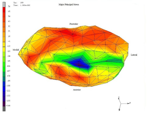
 | Figure 4. Stresses were normally distributed for the normal disc-condyle, forces are 16-62 (MPa) for normal and 94-120 (MPa) for high force at anterior region. |
 | Figure 5. Showed a stress distribution of von mises of disc displacement of grade II that have greatest stress in all the regions with an objectionable random |
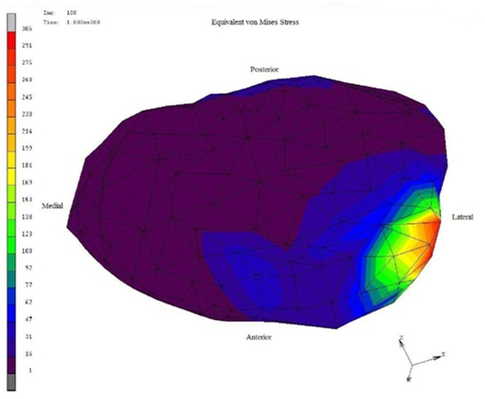 | Figure 6. Von Mises stress distribution, lower stresses 1- 47 (MPa) with blue and green zones for disc and 169-260 (MPa) with red zones for lateral region. |
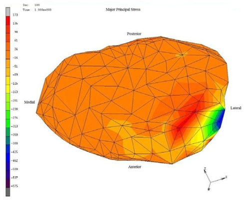 | Figure 7. Von Mises stress distribution of grade III disc displacement, high forces with red and orange zones are for disc with very scant blue and green zones. |
3. Results and Discussion
- Stresses are loaded to the 3-D meshed model as shown at Figure 4 to show the difference between normal and displacement disc.Condylar and temporal cartilage layer along with the TMJ disc play an important role in stress distribution. The presence of TMJ disc and cartilage is believed to prevent load concentration. The cancellous bone of the mandibular condyle can resist compressive and tensile deformation during loading of the TMJ with minimum amount of bone mass due to its plate- like trabecular structure.[8, 11, 12] The loss of posterior teeth with subsequent abnormal loading of the TMJ leads to histomorphological, pathological and pathophysiological changes in the articular cartilage, the articular disc, synovium and bony articular component. The behavior shows the inability of the neuromuscular system to achieve a reduction of the muscular activity in the edentulous side.[41, 42]MRI assessment used in this study because it's very fast, very sensitive, accurate imaging modality, curative single screening method to assess the success of the prosthetic treatment of TMD[ 9, 15, 43]. Although CT can be used but they are applicable only for assessment of density and mineralization degree of the bone and cartilage, so translation of this parameter to a load bearing capacity cannot be performed adequately without biomechanical models and measurement.In this study, the anterior displaced disc were captured by anterior mandibular repositioning splint to show a clinical and MRI successful treatment, then a FEA was used to analyze the stress distribution in the disc because of high incidence of false negative results judged by clinical examination. FEA has been successfully used in this field because it enables us to estimate stresses in the TMJ without invasive approach and also examine not only the pathological status of the joint but also the 3-D relationship among them.[26, 43]In normal TMJ finite element analysis showed a normal distribution of stresses in all the region of the disc .This may be attributed to the disc that well adapting to the histological features and plays an important role in the cushion of intra-articular stress during its conduction .The disc has been shown to exhibite viscoelastic properties through its function as a stress absorber and stress distributor which prevent excessive stress concentration in the cartilage and bone components of the joint and also prevent damage from abnormal prolonged stress .[35,42,43] The distribution of stress in the grade II displaced disc in our study showed non- uniform stress distribution which may be due to an abnormal relationship between the articular disc and condyle. As the disc is forced out of the correct position there is often bone to bone contact which creates surface roughness, additional wear and tear on the joint, and often causes the TMD to worsen. Disc displacement induces change of stress distribution in the disc between articular surfaces, resulting in the secondary tissue damage and change in mechanical properties of the disc(loss of stress absorber function ) The disc displacement in the closed mouth position, usually anteriorly, due to weakness of the discal ligaments .[1,18,28]Von mises stress distribution after using acrylic anterior mandibular repositioning splint in grade II disc displacement showed a uniform distribution of stresses as confirmed by the MRI may be contributed to the forward repositioning of the mandible, keeping a normal disc, condyle, glenoid fossa relationship, and avoiding the click resulting from the jumping of the condyle below the posterior margin of the anteriorly displaced disk, causing the click. Also, acrylic splint has also the advantageous action of assisting the unloading of the joint and enhance adaptation of retrodiscal tissues[44]. Furthermore, the acrylic splint reduced the microtrauma to joint and condylar displacement, thus reducing the inflammation and cytokines release. Grade II displacement had the liability to change to grade I which captured by the splint. The Von mises distribution of grade III disc displacement showed a high stress distributed all over the disc which indicates that it's the worst type of displacement and with the least improvement by this method of treatment. So another treatment modality should be used.
4. Conclusions
- In conclusion, MRI is an objective method for examination of disc displacement before and after treatment with no radiation hazard to the patient, where the anterior mandibular repositioning prosthetic splint was absolutely necessary to improve the variation of abnormal disc –condyle relationship caused by partial loss of teeth as documented by the MRI image processing with finite element analysis, which are used as numerical method to evaluate the stresses for normal and abnormal disc. Understanding of the biomechanical environment of the TMJ is essential for successful treatment and this are provided by mixing between image processing technique with FE methods, finally Grade III disc displacement is a sign of bad omen in the way of anatomical repositioning of the disc affecting different modalities.
References
| [1] | Ingawalé S, Goswami T. Temporomandibular joint: disorders, treatments, and biomechanics. Ann Biomed Eng. 2009; 37(5):976-96. |
| [2] | Detamore MS, Athanasiou KA. Structure and function of the temporomandibular joint disc: implications for tissue engineering. J Oral Maxillofac Surg. 2003; 61(4):494-506. |
| [3] | Gerard, D. A., and J. W. Hudson. The Christensen temporomandibular joint prosthesis system: an overview. TMJ. Journal, 2002. |
| [4] | Wolford LM, Pitta MC, Reiche-Fischel O, Franco PF.TMJ Concepts/Techmedica custom-made TMJ total joint prosthesis: 5-year follow-up study. Int J Oral Maxillofac Surg. 2003; 32(3):268-74. |
| [5] | Detamore MS, Athanasiou KA, Mao J. A call to action for bioengineers and dental professionals: directives for the future of TMJ bioengineering. Ann Biomed Eng. 2007; 35(8):1301-11. |
| [6] | Mayo Clinic, Dental-TMJ Disorders,“http://www.mayoclinic.com/health/tmj-disorders/DS003 55/DSECTION=causes”. |
| [7] | Fricova, M. Horak, Z. Konvickova, S. Jirman, R. Modelling of temporomandibular joint and FEM analysis. Acta of Bioengineering and Biomechanics. 2006; 8(1):37-46 |
| [8] | Mori H, Horiuchi S, Nishimura S, Nikawa H, Murayama T, Ueda K, Ogawa D, Kuroda S, Kawano F, Naito H, Tanaka M, Koolstra JH, Tanaka E. Three-dimensional finite element analysis of cartilaginous tissues in human temporomandibular joint during prolonged clenching. Arch Oral Biol. 2010;55(11):879-86. |
| [9] | Beek M, Koolstra JH, van Ruijven LJ, van Eijden TM.Three-dimensional finite element analysis of the human temporomandibular joint disc. J Biomech. 2000; 33(3):307-16. |
| [10] | Hu K, Qiguo R, Fang J, Mao JJ.Effects of condylar fibrocartilage on the biomechanical loading of the human temporomandibular joint in a three-dimensional, nonlinear finite element model. Med Eng Phys. 2003; 25(2):107-13. |
| [11] | Giesen EB, Ding M, Dalstra M, van Eijden TM.Mechanical properties of cancellous bone in the human mandibular condyle are anisotropic. J Biomech. 2001; 34(6):799-803. |
| [12] | van Ruijven LJ, Giesen EB, van Eijden TM.Mechanical significance of the trabecular microstructure of the human mandibular condyle. J Dent Res. 2002;81(10):706-10. |
| [13] | Liu Z, Fan Y, Qian Y.Comparative evaluation on three-dimensional finite element models of the temporomandibular joint. Clin Biomech. 2008;23 Suppl 1:S53-8. |
| [14] | Chen J, Akyuz U, Xu L, Pidaparti RM.Stress analysis of the human temporomandibular joint. Med Eng Phys. 1998;20(8):565-72. |
| [15] | Pérez Del Palomar A, Doblaré M.Finite element analysis of the temporomandibular joint during lateral excursions of the mandible. J Biomech. 2006; 39(12):2153-63. |
| [16] | Pérez del Palomar A, Doblaré M.An accurate simulation model of anteriorly displaced TMJ discs with and without reduction. Med Eng Phys. 2007; 29(2):216-26. |
| [17] | Hu K, Qiguo R, Fang J, Mao JJ.Effects of condylar fibrocartilage on the biomechanical loading of the human temporomandibular joint in a three-dimensional, nonlinear finite element model. Med Eng Phys. 2003; 25(2):107-13. |
| [18] | Tanaka E, del Pozo R, Tanaka M, Asai D, Hirose M, Iwabe T, Tanne K.Three-dimensional finite element analysis of human temporomandibular joint with and without disc displacement during jaw opening. Med Eng Phys. 2004; 26(6):503-11. |
| [19] | Rao VM, Farole A, Karasick D. Temporomandibular joint dysfunction: Correlation of MR imaging, rthrography and arthroscopy. Radiology. 1990; 174:663-667. |
| [20] | Laskin DM. Diagnosis of pathology of the temporomandibular joint: Clinical and imaging perspectives. Radiol Clin North Am. 1993; 31:135-147. |
| [21] | Berquist T. MRI of the Musculoskeletal System. 4th ed. Baltimore, MD: Lippincott Williams & Wilkins, 2000. |
| [22] | Hayt MW, Abrahams JJ, Blair J. Magnetic resonance imaging of the temporomandibular joint. Top Magn Reson Imaging. 2000; 11:138-146. |
| [23] | Larheim TA, Smith HJ, Aspestrand F. Rheumatic disease of the temporomandibular joint: MR imaging and tomographic manifestations. Radiology. 1990; 175:527-531. |
| [24] | Takebayashi S, Takama T, Okada S, et al. MRI of the TMJ disk with intravenous administration of gadopentetate dimeglumine. J Comput Assist Tomogr. 1997; 21:209-215. |
| [25] | Toyama M, Kurita K, Rivera G. Magnetic resonance arthrography of the temporomandibular joint. J Oral Maxillofac Surg. 2000;58:978-983; discussion 984.11 |
| [26] | Kurita H, Kurashina K, Baba H, Ohtsuka A, Kotani A, Kopp S.Evaluation of disk capture with a splint repositioning appliance: clinical and critical assessment with MR imaging. Oral Surg Oral Med Oral Pathol Oral Radiol Endod. 1998;85(4):377-80. |
| [27] | Bickford W B, 1990, “A First Course in the Finite Element Method”, Richard D Irwin, INC, Boston, pp-7-188. |
| [28] | American Association of Oral and Maxillofacial Surgeons (AAOMS). The temporomandibular joint (TMJ).Retrieved on 10/14/200 7from http://www.aaoms.org/ tmj.php |
| [29] | Chen J, Xu, LF. A finite element analysis of the human temporomandibular joint. J. Biomech. Eng. 1994;116:401–7. |
| [30] | MSC.Marc, 2008, “Theory and User Information”, MARC Analysis Research Corporation, Palo Alto, USA. . |
| [31] | Alomar X, Medrano J, Cabratosa J, Clavero JA, Lorente M, Serra I, Monill JM, Salvador A.Anatomy of the temporomandibular joint. Semin Ultrasound CT MR. 2007 Jun;28(3):170-83 |
| [32] | Koolstra JH, van Eijden TM.Prediction of volumetric strain in the human temporomandibular joint cartilage during jaw movement. J Anat. 2006; 209(3):369-80. |
| [33] | Pérez del Palomar A, Doblaré M.Anterior displacement of the TMJ disk: repositioning of the disk using a Mitek system. A 3D finite element study. J Biomech Eng. 2006;128(5):663-73. |
| [34] | Nagahara K, Murata S, Nakamura S, TsuchiyaT.Displacement and stress distribution in the temporomandibular joint during clenching. Angle Orthod. 1999;69(4):372-9. |
| [35] | Hirose M, Tanaka E, Tanaka M, Fujita R, Kuroda Y, Yamano E, van Eijden TM, Tanne K.Three-dimensional finite-element model of the human temporomandibular joint disc during prolonged clenching. Eur J Oral Sci. 2006; 114(5):441-8. |
| [36] | Langenbach GE, Zhang F, Herring SW, Hannam AG.Modelling the masticatory biomechanics of a pig. J Anat. 2002; 201(5):383-93. |
| [37] | Seligman DA, Pullinger AG.The role of intercuspal occlusal relationships in temporomandibular disorders: a review. J Craniomandib Disord. 1991 spring; 5(2):96-106. |
| [38] | Del Palomar AP, Santana-Penín U, Mora-Bermúdez MJ, Doblaré M.Clenching TMJs-loads increases in partial edentates: a 3D finite element study. Ann Biomed Eng. 2008;36(6):1014-23. |
| [39] | Herring S W.Morphological Correlates of Masticatory Patterns In Peccaries and Pigs. Journal of Mammalogy. 1985;66:603-17. |
| [40] | Koolstra JH, van Eijden TM.Combined finite-element and rigid-body analysis of human jaw joint dynamics. J Biomech. 2005;38(12):2431-9. Epub 2004 Dec 30. |
| [41] | Fei Li ,Min Zhang, Zhong-yi Wang, Hui-ming He: Three –dimensional finite element analysis on the effect of partial anodontia and its restoration to the stress distribution in temporomandibular joint.World journal of modeling and stimulation. Vol.I, No.2, 2005, PP.123-128. |
| [42] | Xi'en Zhang: Anatomy and reconstruction oftemporomandibular joint. Chinese journal of stomatology,16 (198)4,pp.284-251. |
| [43] | Tanaka E, Hirose M, Koolstra JH, van Eijden TM, Iwabuchi Y, Fujita R, Tanaka M, Tanne K.Modeling of the effect of friction in the temporomandibular joint on displacement of its disc during prolonged clenching. J Oral Maxillofac Surg. 2008;66(3):462-8. |
| [44] | Okeson JP: Management of temporomandibular disorders and occlusion.6th edition, Mosby ST Louis,USA,2008. |