-
Paper Information
- Paper Submission
-
Journal Information
- About This Journal
- Editorial Board
- Current Issue
- Archive
- Author Guidelines
- Contact Us
Advances in Computing
p-ISSN: 2163-2944 e-ISSN: 2163-2979
2011; 1(2): 24-28
doi:10.5923/j.ac.20110102.04
Monitoring of Geographically Distributed Moving Objects
 Abstract
 Reference
 Full-Text PDF
 Full-text HTML
Dr. Ghazi H. Shakah1, Vector Krasnoproshin2, Aleksander Valvachev3
1Dean of the Faculty of Computer and Information Technology, Ajloun National University, Jordan
2Dept. Information Management Systems, Belarusian State University, Minsk, Belarus
3Dept. of Information Management Systems, Belarusian State University, Minsk, Belarus
Correspondence to: Dr. Ghazi H. Shakah, Dean of the Faculty of Computer and Information Technology, Ajloun National University, Jordan.
| Email: |  |
Copyright © 2012 Scientific & Academic Publishing. All Rights Reserved.
The paper dwells on how to build monitoring systems for industrial moving objects on the basis of the multi-agent approach and image recognition techniques. The problem of monitoring for diverse business applications is considered. Basic ontological models of the monitoring participants were built, an algorithm to evaluate the object states and generate proper controls was suggested. Five key processes realizing monitoring were distinguished. The architecture for corresponding program agents was suggested together with schematics of their interaction to implement the monitoring processes in the Internet environment.
Keywords: Monitoring, Agent Approach, Image Recognition, Monitoring Systems
Cite this paper: Dr. Ghazi H. Shakah, Vector Krasnoproshin, Aleksander Valvachev, Monitoring of Geographically Distributed Moving Objects, Advances in Computing, Vol. 1 No. 2, 2011, pp. 24-28. doi: 10.5923/j.ac.20110102.04.
Article Outline
1. Introduction
- The quality of human life is determined by the quality of the surrounding environmental conditions. In order to reveal negative changes in the environment and find the ways of their elimination monitoring is used.In its conventional meaning “monitoring is acomprehensive process of observation, evaluation and prediction of changes in the biosphere conditions resulting from natural and anthropogenic factors[1]". Depending on the scope of observations monitoring can be divided into global, regional, and local. As a rule, monitoring involves three basic components: observation of the objects, evaluation of their condition by the given attributes and generation of the adequate control decision.The latest 100 years have seen the development of monitoring technologies in the frame of ecological research. Special importance was attached to monitoring in the period of atomic tests (1945-1963) as it helped to minimize negative impact of the radioactive fall-out on the people. Papers such as E.Odum, M.Budyko, M.Begom, J.Harper, S.Pimm, Y.Israel, and others are devoted to the monitoring techniques and approaches.Conventionally stationary objects have been the targets for monitoring (wildlife sanctuaries, natural-territorial habitats, testing grounds, etc.). In general this kind of monitoring was a part of some current task with a few of diagnosticindicators, changed occasionally[2].In the recent years the term monitoring is referred to social, military, logistic, and other issues. Correspondingly monitoring is understood as a package of measures including observing, measuring, evaluating, and decision-making to support the management of natural and anthropogenic systems. The problems have become more sophisticated, whereas the time available to find solutions is little in the opinion of many scientists.Changing boundaries, market globalization, intensified competition, and labor internationalization together lead to redistribution of energy resources. The number of mobile industrial structures (further – objects), potentially hazardous for the environment, have swollen up respectively. These objects include, first of all, the rolling stock, high-capacity motor transport, and water craft (tankers and dry-cargo freighters) carrying petrochemicals, liquefied gas, wastes of nuclear power plants, and similar products. The traffic of this kind of objects has been intensifying and their number is increasing all over the globe every year. The experience of the recent years proves that despite of all of the precautions taken, accidents and disasters are inevitable. As a result we have plenty negative effects on the human health and life, namely smoke pollution, gas and harmful chemical contamination of densely populated areas and agricultural lands.To prevent such situations from happening and provide immediate response in cases of emergency it is necessary, in the opinion of the authors, to work out the techniques and technologies for permanent monitoring of potentially hazardous mobile technical systems. Rapid development of the global network – the Internet as well as inexpensive highly efficient communication and global positioning equipment provides a favorable opportunity to find a solution.The objective of this paper is to study possible ways of building a computer architecture intended for set up and support of automated monitoring of the geographically scattered mobile technical systems (objects).
2. Setting the Objectives
- When setting the objectives for this study the authors took into consideration the need for representation of multiple realistic cases, therefore the objectives and the solution can be considered in a certain sense typical for monitoring[3].The given conditions: the company W, including the control center H, and n of mobile objects to be managed G = G1,G2,…,Gn. The objects (for instance a diesel unit and n of cistern cars) are participating in a certain mission (for example, transporting petroleum). The success of the mission depends on the state of the objects[4].The state of the objects G is characterized by a finite number of diagnostic variables:X = (X1,X2,…,Xm)The G objects are geographically scattered and change their geographical positions KtG with time:Kt1G ≠ Kt2G In order to evaluate the current state of the objects the W company management should periodically meet the challenge of monitoring M, which implies evaluation of the state (V) of the objects (G) based on the current values of the variables X, as well as synthesis of the proper control decision (U):M à U = f (X, V)The need is to develop the system architecture Sys that would provide automated solution for the problem of monitoring M.The requirement to the solution: invariance of the monitoring time to the number of objects (t à 0 with n à∞).We shall accept the following considerations as the basis for the solution:the feature of the problem set is the geographical distribution of the objects and, correspondingly, scattered nature of the information on their state. In the majority of cases the multi-agent approach[5] is used to solve this kind of problems;as per the process approach[6] the solution of the problem can be reduced to five processes, namely building the company W, acquiring information X from the objects, transmitting X to the center, integrating X into the central DB, processing X to evaluate V of the object and generate a proper control decision U.Comparing the results of the agent and process approaches we can make the following first conclusion: the architecture Sys must include five agents, all of which will contribute to the monitoring solution embracing five processes mentioned above.
3. Key Models
- In order to create a theoretical basis for the solution a set of models is suggested grounded by the ontological approach[3], promoted in the Belarusian State University of Informatics and Radioelectronics and Belarusian State University[5-7].Ontology is a formal specification of the divisible conceptual model[3]. Ontology involves content classes of object regions, properties of these classes, links between the classes, and affirmations, made of these classes, their properties and links between them. In what follows we shall name ontological models simply “models” for convenience.In compliance with the logics of the monitoring problem, first of all it is necessary to build a model of the company, which will perform monitoring.The company model must include at least the attributes of the center and objects:W = (H, G1, G2, …, Gn)The model of the center contains the global identification attributes, list of monitoring objectives, a server, processing software F for indicators X, and the database:H = (AH, idH, task, S, PL, DB)where: AH – is the global address of the center; idH – center’s identifier; task –the monitoring tasks; S – server; PL – programs to synthesize states and controls; DB – is the database to accumulate the data sent by the detectors.The model for the problem of monitoring synthesis is similar to the classical control problem[4]:U = F (X,V)where: F – is the control choice function for the object depending on its state.The object model involves the components, necessary to identify the object in the Internet, acquire object data, and transmit it to the center for processing:G = (AG, idG, KG, d1,d2,…, dm, Ks, Box, Kp)where: AH – is the global address of the object; idG – the object’s identifier; G – current position data; d – detectors; Ks – is the controller to read and analyze the signals from the detectors; d – detectors; Box – a message from the object to the center; Kp – is the controller for data exchange between the objects and the center.The model of the package includes the addresses of the sender and recipient, object identifying attributes, and detector readings:Box = (AH,AG, idG, X)On the whole the models 1-6 are the basis for the solution. The ontological approach used enables to specify them to the level of the program code. The overall monitoring diagram is plotted in Figure 1.This diagram is of an open nature and can be extended indefinitely by increasing the number of the objects to be monitored G. The time t required for the control U synthesis is invariant to the number of objects, since the processes to acquire the vector values for diagnostic variables X have been multi-sequenced. One of the possible alternatives to arrange the agent architecture that implements this scheme is given below.
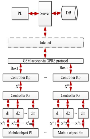 | Figure 1. Scheme of monitoring |
4. System Architecture
- The system architecture consists of the modules performing the processes that contribute to the solution. It has been mentioned above that the solution should be reduced down to five processes that would, as a whole, support monitoring; therefore there must be five agents[6, 7].The processes are synchronized by the company management; thus we shall primarily build the model of the agent that generates the model of the hierarchy including the attributes of all the animate and virtual (programs, devices) participants (Figure 2).
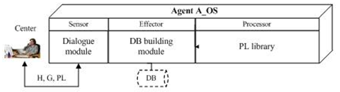 | Figure 2. Architecture of the company model agent |
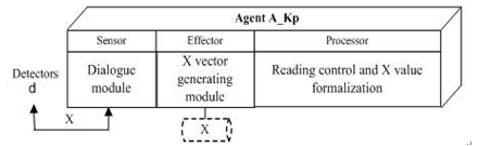 | Figure 3. Architecture of the agent to generate the indicator value vector |
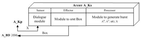 | Figure 4. Burst generating agent architecture |
 | Figure 5. Application agent architecture |
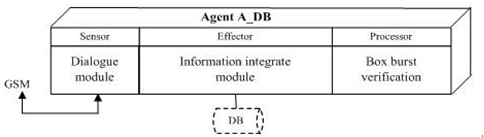
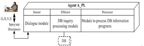 | Figure 6. Architecture of the inquiry processing and application agent |
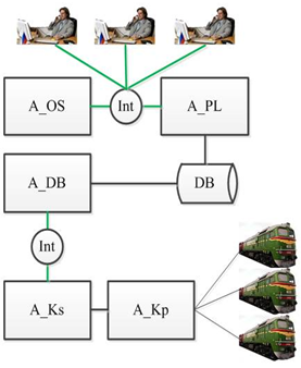 | Figure 7. Monitoring system architecture |
5. Conclusions
- This paper has discussed the issues related to building flexible software-hardware architectures to arrange and support monitoring of geographically scattered mobile objects.A broad concept for monitoring has been suggested on the basis of the synthesizing the process and multi-agent approaches, and digital communication and web-interface technologies.The problem of monitoring for diverse business applications is considered. Basic ontological models of the monitoring participants were built, an algorithm to evaluate the object states and generate proper controls was suggested. Five key processes realizing monitoring were distinguished.The architecture for corresponding program agents was suggested together with schematics of their interaction to implement the monitoring processes in the Internet environment.