-
Paper Information
- Next Paper
- Previous Paper
- Paper Submission
-
Journal Information
- About This Journal
- Editorial Board
- Current Issue
- Archive
- Author Guidelines
- Contact Us
American Journal of Materials Science
p-ISSN: 2162-9382 e-ISSN: 2162-8424
2016; 6(4A): 67-71
doi:10.5923/c.materials.201601.13

Synthesis and Characterization of Alumina Filler Reinforced Polyurethane Foams for Light Weight Applications
 Abstract
 Reference
 Full-Text PDF
 Full-text HTML
Jathin K. J.1, Chinthankumar D. M.1, Manujesh B. J.1, Umashankar K. S.1, Prajna M. R.2
1Department of Mechanical Engineering KVGCE, Sullia, D.K, Karnataka, India
2Department of Computer Science & Engineering, KVGCE, Sullia, D.K, Karnataka, India
Correspondence to: Manujesh B. J., Department of Mechanical Engineering KVGCE, Sullia, D.K, Karnataka, India.
| Email: |  |
Copyright © 2016 Scientific & Academic Publishing. All Rights Reserved.
This work is licensed under the Creative Commons Attribution International License (CC BY).
http://creativecommons.org/licenses/by/4.0/

The need of light materials that exhibit high strength to weight ratio is finding a new area of interest in recent days. The rigid polyurethane foams are one among them which shows good mechanical properties and are used in various structural applications. Present work aims at determining mechanical properties of the alumina filler filled polyurethane foams. The rigid polyurethane foams reinforced with alumina fillers (3%, about 18.23g, 45μm and 99.7% purity) in order to increase mechanical properties and to minimize the bubble formation. The mechanical properties such as flexural and compression strength was examined. The test results showed that higher density PU foams show better performance. The inclusion of the filler has drastically minimized the bubble formation during the foaming process.
Keywords: Alumina filler, Rigid, Polyurethane (PU), Foam, Flexural, Compression
Cite this paper: Jathin K. J., Chinthankumar D. M., Manujesh B. J., Umashankar K. S., Prajna M. R., Synthesis and Characterization of Alumina Filler Reinforced Polyurethane Foams for Light Weight Applications, American Journal of Materials Science, Vol. 6 No. 4A, 2016, pp. 67-71. doi: 10.5923/c.materials.201601.13.
Article Outline
1. Introduction
- In the olden days, manufacturing companies were used to construct the product using spare materials. The materials used as spares include bricks, stones, wood, iron and steel. Use of these materials and methods were implemented during eighteenth to nineteenth century of industrial revolution [1]. But the handling of products which was constructed by using these materials became difficult. Handling of these materials resulted in higher energy consumption and made the system bulk. But the materials such as iron and steel are used even today in the construction of variety of products due to its high strength [1]. During the year 1709 the researcher named Abraham Darby developed techniques to produce cast iron [1]. At the end of eighteenth century, the wrought iron was replaced with cast iron. Later in the year of 1850 mild steel production techniques were developed by the research worker named as Henry Bessemer [1]. As an effect most economical steels were developed. During 19th century revolution has taken part in the field of light weight structures. At the beginning of 20th century industrially developed light weight structures are started to emerge. Polymer foams are first invented in the 1930's and 40's, with foamed polystyrene being the first polymer foam made in 1931 [2, 3]. Polyurethane was found by Dr. Otto Bayer during the beginning of the Second World War. That was first used as a replacement for rubber. Polyurethanes are divided into rigid foams and flexible foams [2]. Flexible PU foams are soft and used for cushioning applications. Polyurethane (PU) rigid foams have good thermal properties than thermoplastics and thus commonly used for insulation purposes. They have low thermal conductivity [2].With the growing concern for energy conservation, there is a need to improve the properties of rigid foams. This can be achieved by making the foams with smaller cell sizes. Another method is by adding fillers which will act as diffusion barriers. Fillers can inhibit the bubble growth by affecting local archeology surrounding the growing bubbles. Fillers have been successfully used in thermoplastic foams to reduce cell size [4]. There were lots of studies carried out by reinforcing different types of fillers in polyurethane foaming process [4-6].Therefore the work aims at the synthesis and characterization studies on mechanical properties of polyurethane foam reinforced with alumina filler with varied foam densities.
2. Materials and Methods
- The raw material used for the production of polyurethane foam was obtained from Polynate Foams Pvt. Ltd, Bangalore, Karnataka State, while the Alumina powder was obtained from S. P Circle Shop, Bangalore.
2.1. Materials
2.1.1. Alumina Filler for Reinforcement.
- The mechanical properties of polymer foams can be improved by adding fillers [4]. In this study the alumina fillers of 45 micron and 99.7% purity is used as reinforcing agents. The use of fillers for reinforcement of polymers foams is a new technology which throws high expectations since they improve the mechanical properties. Improved mechanical properties could allow a reduction in the amount of material needed for an application [6].
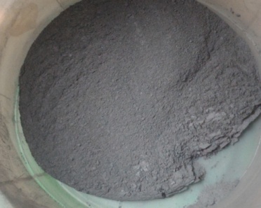 | Figure 1. Alumina Filler |
2.1.2. Polyurethane Foam Components
- There are two main components necessary for the formation of polyurethane foam, namely Polyol and diphenylmethane diisocyanate (MDI). Commercially polyol is represented as part B and diphenylmethane diisocyanate (MDI) is represented as part A. The chemicals being supplied by Polynate Foams Bangalore.
2.1.3. Mold Box
- The mold box is prepared by the use of M.S steel. It is welded to the dimension of 300x300x25mm. During the foaming process there will be a tremendous temperature and pressure setup, to resist this condition the mold box was fabricated with the help of M.S steel. Surface of the mold box is covered by the help of Teflon sheets for the purpose of easy removal of fabricated foam.
2.2. Procedure for the Foam Production
- The PU foams with and without varied content of fillers were prepared by the following method.
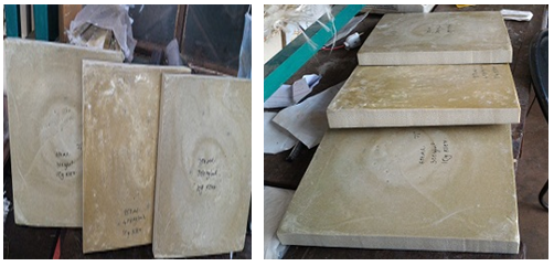 | Figure 2. Produced PU Foam Blocks |
2.3. Preparation of Testing Specimens
- The test samples are prepared as according to the ASTM standards. For the purpose of performing flexural and compression tests, the foams were cut in accordance to the ASTM C 393/C 393M- 06 and C365/C 365M-05 respectively. Below Figures 3 and Figure 4 show the test specimens to perform flexural and compression tests.
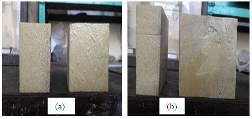 | Figure 3. (a) Specimen for Flat Wise Compression (b) Specimen for Edge Wise Compression Test |
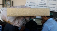 | Figure 4. Specimen for Flexural Test |
4. Results and Discussions
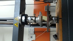
- The prepared specimens were tested using the Universal Testing Machine (ZWICK/ ROELL Z020) in KONSPEC, Pvt. Ltd. Mangalore.
4.1. Flexural Testing
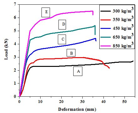
- The test span length of the samples was set to 100mm and the load is applied at the mid span of span length. It was observed that a 6 mm (maximum) deflection due to bending, and load was continuously applied till the fracture of the specimens. The Figure 5 shows the specimen under 3- Point Bend Test.
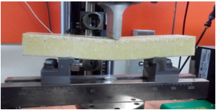 | Figure 5. Specimen under 3- Point Bend Test |
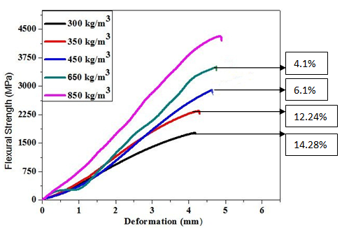 | Figure 6. Flexural Curves under 3P Bend Test |
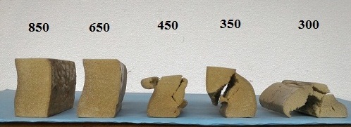
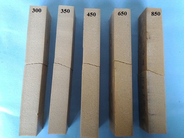 | Figure 7. The post test 3- Point bend specimens |
4.2. Compression Strength
- Under this study flat wise and edge wise compression tests were performed. During this test 2mm/min loading speed was adopted.
4.2.1. Edgewise Compression
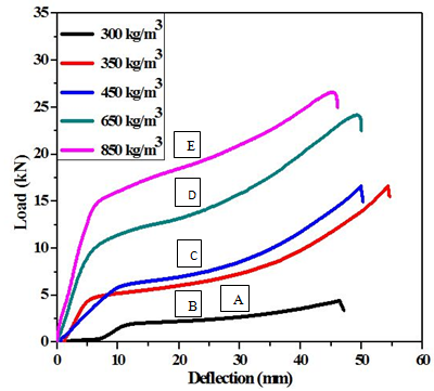
- The Figure 8 shows the Edgewise Compression Test. The edgewise compression tests conducted to explore the foam properties on the transverse direction.
 | Figure 8. Edgewise Compression Test |
 | Figure 9. The Edgewise Compression test curves |
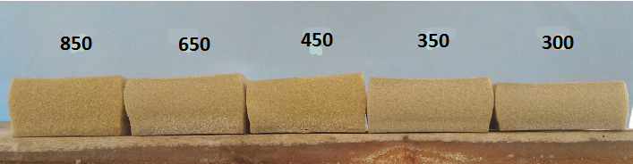
 | Figure 10. Edge wise compressed specimens |
4.2.2. Flatwise Compression
- The Figure 11 shows the flatwise compression test curves. The tests also prevailed with 3 different phases. The curves indicate the clear formation of plateau which enables the compressive loading. For the present studies it was observed that for the foam specimens of densities 300kg/m3, 350kg/m3, 450kg/m3, 650kg/m3, 850kg/m3 the flatwise compressive strength was observed to be 55.8%, 50%, 41%, 36.36% and 25% respectively.
 | Figure 11. Fatwise Compression test curves |
 | Figure 12. Flat wise compressed specimens |
5. Conclusions
- The paper attempts to synthesize the alumina filler reinforced polyurethane foam slabs with five different densities using one step one shot method. The foaming process is observed to be associated with the huge pressure and few typical arrangements were developed to overcome the set-up pressure optimized mold design. The alumina fillers used in the study has modified the foaming process. The good cure kinetics has been observed during the process which showed better mechanical properties. The bubble formation has drastically reduced and thus resulted with minimum flaws in the foaming process. The flexural and compression studies have revealed that the filler reinforced PUF witness better properties than unfilled. It is concluded that the mechanical strength is directly related to foam density.