Ravikantha Prabhu1, Sharun Mendonca1, Darren1, Gladson1, Thirumaleshwara Bhat2
1Department of Mechanical Engineering, St Joseph Engineering College, India
2Department of Mechanical Engineering, Shri Madwa Vadiraja Institute of Technology and Mangement, India
Correspondence to: Ravikantha Prabhu, Department of Mechanical Engineering, St Joseph Engineering College, India.
| Email: |  |
Copyright © 2016 Scientific & Academic Publishing. All Rights Reserved.
This work is licensed under the Creative Commons Attribution International License (CC BY).
http://creativecommons.org/licenses/by/4.0/

Abstract
This study examines physical, mechanical and tribological properties of polypropylene (PP) and low density polyethylene (LDPE) sample prepared by manual lever operated plunger injection moulding equipment. In addition, calcium carbonate (CaCO3, 20%) is added to the polymer material as an additive and the properties of the composite have been tested. The results showed that 20%-CaCO3 addition improved hardness, tensile property and tribological property of the PP and LDPE.
Keywords:
Injection moulding, Polypropylene, Low density polyethylene, Calcium carbonate
Cite this paper: Ravikantha Prabhu, Sharun Mendonca, Darren, Gladson, Thirumaleshwara Bhat, Mechanical and Tribological Properties of Injection Moulded Modified CaCO3/PP, LDPE Composites, American Journal of Materials Science, Vol. 6 No. 4A, 2016, pp. 61-66. doi: 10.5923/c.materials.201601.12.
1. Introduction
Polymer composites in recent years have attracted increasing attentions because of their significant improvement in mechanical properties, thermal stability and electrical properties over the matrix polymers [1]. Addition of nanopowders of different compounds such as Aluminium Oxides (Al2O3) [2], glass fibers [3], carbon nanotubes and carbon black [4], to polymers is believed to produce new polymer composites with improved mechanical, thermal and tribological properties in addition to being relatively cost-effective fillers compared to their original counterparts. This may result in new industrial applications and solutions [5]. These additives are believed to affect the tensile properties, packing characteristics and interfacial bonding of the polymer leading to enhanced properties for industrial and technological applications. Improvement of mechanical properties has been attributed to formation of conjugated biphasic material due to addition of fillers. These fillers will then tolerate some of the applied tension to the polymer matrix leading to enhanced tensile properties of the end product [6]. One of the most common fillers is the calcium carbonate (CaCO3) which has been used as a cheap substitute to the Polyol for the production of flexible polyurethane foam leading (widely used in industry) to enhanced mechanical properties of the end product [7]. Incorporation of CaCO3 in thermoplastic production is a common practice for reduced production cost in plastic industry [8]. It has been reported that the addition of CaCO3 nanoparticles could improve the thermal, mechanical and tribological properties of polypropylene (PP) [9]. This project mainly deals with analysis of CaCO3 reinforced PP and LDPE composite, which are moulded into the shape of the die prepared as per ASTM standard using self fabricated lever operated plunger injection moulding machine on a low budget, which can be operated manually with less effort. The finished products are tested for its various physical, mechanical and tribological properties.
2. Materials and Methods
2.1. Injection Moulding Setup
The injection moulding machine consists of 1. The hopper. 2. Heater setup. 3. Hand operated lever. 4. Plunger. 5. Bench vice. 6. Die cavity The construction of injection moulding setup is as shown in figure 1.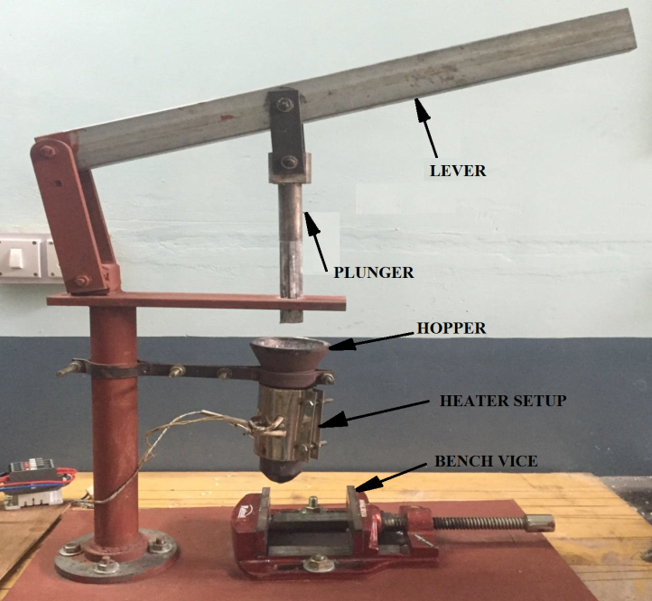 | Figure 1. Injection moulding setup |
2.1.1. Hopper
This device is used to store the polymer and it houses the heater setup. The polymer is melted to its melting point and is injected through the hopper due to the force applied. Thermoplastic material is supplied to moulder in the form of small pellets. The hopper on the injection moulding machine holds these pellets. The pellets are gravity-fed from the hopper through the hopper throat into the barrel provided with heater setup.
2.1.2. Heater Setup
This device is used to limit the temperature, within the required or desired temperature limit stated by the user. Depending on the material to be injected the temperature is set, after which once the required temperature is reached the heating process stops. This setup is connected to the barrel.
2.1.3. Hand Operated Lever
For this machine a second law lever system is used, where one end is hinged. The plunger is attached to the middle of the lever and the other end is free through which the force is applied.
2.1.4. Plunger
It is a cylindrical rod which is attached to the lever and which supplies the pressure onto the polymer material which needs to be injected onto the die cavity. The dimensions of the die are same as that of the inner diameter of the hopper.
2.1.5. Bench Vice
This mechanical device is normally bolted to the base plate of the machine. Vices have two parallel jaws, one fixed and the other movable, threaded in and out by a screw mechanism.
2.1.6. Die
It consists of a hollow impression to which the material is forced. Die cavity is as shown in figure 2.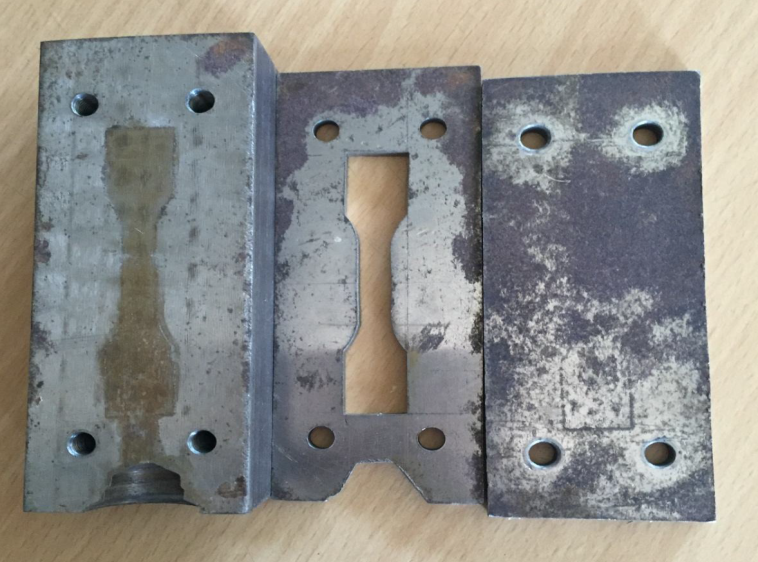 | Figure 2. Die Cavity |
2.2. Fabrication of Composite Specimen
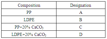
Polymer injection moulding machine consists of a hopper, plunger, lever and mould cavity of desired shape. Column is mounted on base plate. Barrel is attached to the column. Mould cavity is fixed under the barrel using bench vice. The polymer used for analysis is polypropylene and low density polyethylene with CaCO3. Mould cavity is prepared with the negative of desired shape for tensile test. Measured quantity of polymer and CaCo3 is added with the ratio 8:2. In the barrel, the polymer is in liquid state, because it is heated at a temperature 175-210°C by heater which is controlled temperature controller. When the force is applied on the rod which is connected to plunger with lever mechanism, the plunger moves down forcing the polymer out. The polymer moves into cavity forming the shape of the mould cavity. After solidification, operator releases the force on the rod which moves the plunger upward. The mould cavity is removed from the vice. The mould is opened to eject the moulded part and another cycle is repeated.Table 1. Designations and detailed compositions of the composites
 |
| |
|
2.3. Preparation of Test Samples
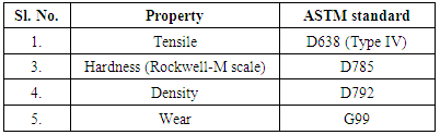
Test specimens are prepared as per ASTM standards. Five samples of each type were cut and prepared for the test. The list of ASTM standards used is mentioned in Table 2.Table 2. Sizes of specimens as per ASTM standards
 |
| |
|
2.4. Physical Characterization of the Composites
Density: The densities of composites were measured by the displacement method based on Archimedes’s principle. In this technique distilled water was taken in the measuring jar having graduations in milliliters and the initial level of water was noted. Then each of the samples was weighed using an electronic balance of AY220 type (Shimadzu Corporation, Japan with 0.1mg accuracy). The weighed samples were then dropped into the water in the measuring jar. This resulted in rise of water level in the jar. The final level of water was noted and the difference in the final and initial readings gave the volume of water displaced. The volume of water displaced was equal to the volume of the sample dropped into it. The ratio of the weight of the sample to its volume as obtained by the above procedure yielded the density of the composites.
2.5. Mechanical Characterization of Composites
2.5.1. Hardness
Hardness of a material is defined as the resistance to deformation, particularly permanent deformation, indentation or scratching. The hardness of the different composite specimens was determined on a Rockwell Hardness testing machine using M-scale. Here the major loads applied were 100N. The loading was done for a short period of 10 seconds.
2.5.2. Tensile Test
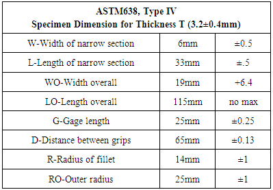
Tensile tests were conducted using universal testing machine with across head speed of 5mm/min. In each case, five samples were tested and average value tabulated. Tensile test samples were cut as per ASTM D638 Type IV test procedure. Tests were carried out at room temperature and each test was performed until tensile failure occurred.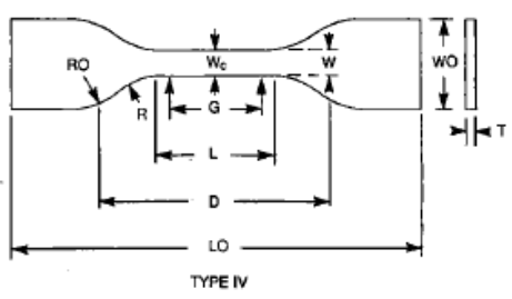 | Figure 3. Tensile test specimen (ASTM638, Type IV) |
Table 3. Tensile specimen dimensions
 |
| |
|
2.6. Wear Testing Details
The wear properties of composite samples were tested on the wear and friction monitor commonly known as Pin-on-Disk machine. The samples were cut according to the ASTM standard G99. The test samples were then glued to the mild steel pins of 10mm square cross-section and 40mm length. The track radius of 30mm was set, the specimen is held stationary and the disk is rotated while a normal load is applied through a lever mechanism. A series of tests were conducted with sliding velocities of 1.5 m/s under normal loading of 50N for a sliding distance of 1500m. Frictional force is noted down and the material loss from the composite surface is measured using a precision electronic balance with accuracy ±0.1mg. The specific ware rate (Ws) was calculated from following Equation 1.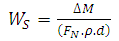 | (1) |
Where, ΔM is the mass loss, ρ is density, FN is applied load and d is sliding distance. Coefficient of Friction (COF) was determined as per Equation 2. | (2) |
3. Results and Discussion
This chapter presents the physical, mechanical and wear characterization of the class of polymer matrix composite developed for the present investigation. They are reinforced with 20% percentage CaCO3. The results of various characterization tests are reported here.
3.1. Density
It is the simplest property which can be measured when the composites are developed. Density of a material is its mass per unit volume. The density of the neat polypropylene and Low density polyethylene is found to be 0.9g/cm3 and 0.93g/cm3 respectively. The addition of the CaCO3 resulted in increase in the density of the composite. Increase in density is an obvious effect due to the high density of CaCO3 (2.73 g/cm3). The variation is as shown in figure 4.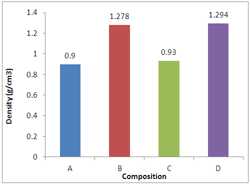 | Figure 4. Densities comparison of different composite specimens |
3.2. Mechanical Properties of Composites
Development of CaCO3 reinforced PP and LDPE composite with improved property requires understanding of mechanical behaviours.
3.2.1. Hardness
Hardness of the PP and LDPE found to be 55 RHN and 15RHN respectively. The addition of the CaCO3 resulted in improvement in the hardness to 68RHN for PP and 20RHN for LDPE. The graph is plotted using the results of hardness test is as shown in figure 5.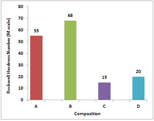 | Figure 5. Comparison between hardness of different composite specimens |
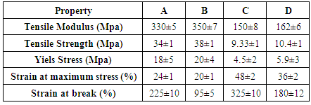
3.2.2. Tensile Strength
The result of the tensile testing conducted as per ASTM standard, are given in Table 4. It is observed from the table that the addition of the CaCO3 has improved tensile property of the PP and LDPE polymers. Tensile modulus is found to be increased by 6.06% for PP and 8% for LDPE. Tensile strength found to be increased by 11.76% for PP and 11.46% LDPE. Whereas, strain at maximum stress and strain at breakage has reduced due to CaCO3 addition.Table 4. Tensile properties
 |
| |
|
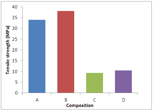
Comparison between the tensile modulus and tensile strength are as shown in figure 6-7.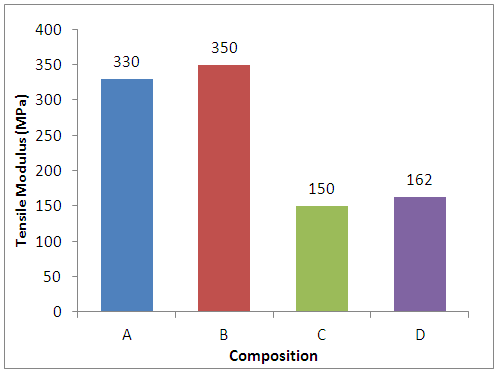 | Figure 6. Tensile strength of different composite specimens |
 | Figure 7. Tensile modulus of different composite specimens |
3.3. Dry Sliding Wear Property
3.3.1. Specific Wear Rate
Dry sliding wear occurs when a hard rough surface slides across a softer surface. ASTM International (formerly American Society for Testing and Materials) defines it as the loss of material due to hard particles that are forced against and move along a solid surface.The wear loss is found to be maximum for plain PP and LDPE the addition of 20%, CaCO3 resulted in decrease in wear loss.
3.3.2. Coefficient of Friction
Variations in COF values for different test samples are presented in Figure. COF shows varying trend and it found to be minimum for LDPE and maximum for PP+CaCO3 composite. It is clear from the graph that the addition of CaCO3 resulted in the increase of Coefficient of friction.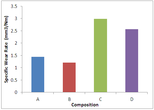 | Figure 8. Specific wear rate of different composite specimens |
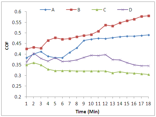 | Figure 9. Coefficient of friction (COF) |
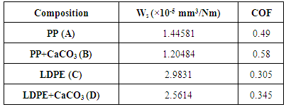
Table 5. Dry sliding wear properties
 |
| |
|
4. Conclusions
PP/CaCO3 and LDPE/CaCO3 composites are developed using lever operated injection molding machine. It is found that the addition of low quality 20%, CaCO3 resulted in improvement in the physical, mechanical and tribological property of the composite. Tensile modulus is found to be increased by 6.06% for PP and 8% for LDPE. Tensile strength found to be increased by 11.76% for PP and 11.46% LDPE. Whereas, strain at maximum stress and strain at breakage has reduced due to CaCO3 addition.
ACKNOWLEDGEMENTS
The authors extend heartfelt thanks and appreciations to Director and Principal of St Joseph Engineering College, Mangaluru for their continuous support and encouragement during research work.
References
| [1] | Y. Lin, H. Chen, C.M. Chan, J. Wu, “Nucleating effect of calcium stearate coated CaCO3 nanoparticles on polypropylene,” J. Colloid Interface Sci., 354 (2), pp. 570–576, 2011. |
| [2] | Pool K.V., Dharan C.K. H., Finnie I. “Erosive wear of composite materials”. Wear, 107, 1-12(1986). |
| [3] | Kaynak C., Arikan A., Tincer T. “Flexibility improvement of short glass fiber reinforced epoxy by using a liquid elastomer”. Polymer, 44, 2433–2439 (2003). |
| [4] | Chen Z.-K., Yang J.-P., Ni Q.-Q., Fu S.-Y., Huang Y.-G. “Reinforcement of epoxy resins with multi-walled carbon nanotubes for enhancing cryogenic mechanical properties”. Polymer, 50, 4753–4759 (2009). |
| [5] | Zhou S.S., Wu L.M., SunJ., Shen W. “The change of the properties of acrylic –based polyurethane via addition of nano-silica. Progress in Organic Coatings”, 45, 33-42(2002). |
| [6] | Callister W. D. “Materials science and engineering: an introduction. John Wiley & Sons, New York” (2000), ISBN: 0471135763. |
| [7] | Usman M. A., Adeosun S. O., Osifeso G. O. “Optimum calcium carbonate filler concentration for flexible polyurethane foam composite”, Journal of Minerals and Materials Characterization and Engineering, 11, 311-320 (2012). |
| [8] | Rai U.S., Singh R.K., “Synthesis and mechanical characterization of polymer-matrix composites containing calcium carbonate/white cement filler”, Materials Letters, 58,235– 240 (2003). |
| [9] | Z. Zhang, C. Wang, Y. Meng, K. Mai, “Synergistic effects of toughening of nano-CaCO3 and toughness of β-polypropylene,” Compos. Part A: Appl. Sci. Manuf., 43 (1), 189–197, 2012. |

 Abstract
 Reference
 Full-Text PDF
 Full-text HTML