-
Paper Information
- Next Paper
- Previous Paper
- Paper Submission
-
Journal Information
- About This Journal
- Editorial Board
- Current Issue
- Archive
- Author Guidelines
- Contact Us
American Journal of Materials Science
p-ISSN: 2162-9382 e-ISSN: 2162-8424
2015; 5(3C): 157-161
doi:10.5923/c.materials.201502.31
Finite Element Investigations of Temperature Distribution in Fins with Circular Perforations
 Abstract
 Reference
 Full-Text PDF
 Full-text HTML
M. Sudheer 1, Ashwin Shetty 1, Shashiraj Somayaji 2
1Department of Mechanical Engineering, St Joseph Engineering College, Mangaluru, Karnataka, India
2Department of Mechanical Engineering, B.M.S College of Engineering, Bengaluru, Karnataka, India
Correspondence to: M. Sudheer , Department of Mechanical Engineering, St Joseph Engineering College, Mangaluru, Karnataka, India.
| Email: |  |
Copyright © 2015 Scientific & Academic Publishing. All Rights Reserved.
This study examines the heat transfer enhancement achieved from a vertical rectangular fin embedded with circular perforations under natural convection as compared to an equivalent solid (non-perforated) fin. The effect of perforation profile, diameter of the perforation and its pitch on the temperature distribution are analysed by using finite element method. Establishing finite element procedure for heat transfer analysis of fins with perforations and comparing performance of perforated fin results verses non-perforated fins; it was observed that perforated fins show considerable reduction in temperature. The increase in perforation diameter resulted in reduced fin temperatures compared to all other variations and is suggested to be the best measure for enhancement of heat transfer. The finite element method results closely match with published experimental thermocouple results of previous investigators within ±10% deviation. The finite element analysis procedure developed can be used for heat transfer analysis of fins with different kinds of perforation.
Keywords: Natural convection, Perforate fin, Finite element analysis
Cite this paper: M. Sudheer , Ashwin Shetty , Shashiraj Somayaji , Finite Element Investigations of Temperature Distribution in Fins with Circular Perforations, American Journal of Materials Science, Vol. 5 No. 3C, 2015, pp. 157-161. doi: 10.5923/c.materials.201502.31.
Article Outline
1. Introduction
- Enhancement of heat transfer is of vital importance in many industrial applications. The thermal systems must be designed and sized to generate, transmit, or dissipate the appropriate amount of unwanted heat with required demand. The removal of excessive heat from system components is essential to avoid the damaging effects of burning or overheating. The enhancement of heat transfer is an important part the subject of thermal engineering [1]. Fins, as heat transfer enhancement devices, have been quite common. A large number of studies have been conducted on optimizing fin shapes. Other studies have introduced shape modifications by cutting some materials from fins to make cavities, holes, slot, grooves or the channels through the fin body to increase heat transfer areas and or the heat transfer coefficient [2].In a recent literature, Huang et al. [3] indicated that optimum heat sink design always have the lowest average base plate temperature and can decrease from 6.3% to 7.3% when compared with the solid pin fin array. Ehteshum et al. [4] have observed that increasing the number of perforations have shown remarkable heat transfer enhancement and also considerable saving in weight in comparison with solid fins.Al-Essa and Al-Widyan have [5] concluded that heat dissipation rate for the perforated fin is a strong function of both the perforation diameter and lateral spacing. They mentioned that this function attains a maximum value at a given perforation diameter and spacing, which are called the optimum perforation dimension. In an earlier study, Al-Essa [6, 7] reported same observation in case of fins with square and rectangular perforations. It was also mentioned that heat transfer enhancement is proportional to fin thickness and its thermal conductivity. While comparing the performances of circular and square perforated fins, Ismail et al. [8] stated that both have almost the same amount of heat removal rate but circular perforated fins have significantly less pressure drop than that of square perforated fins. Kumbhar et al. [9] have evaluated the thermal performances of fins with circular perforations by both experimental and finite element technique. They observed a close match between the results by both the methods. In a performance comparison, Baruah et al. [10] concluded that the overall performance of elliptical pin fin heat exchanger increased by 23% by introducing elliptical perforations when compared to solid elliptical fins. Jassem [11] has evaluated the effect of form of perforation on temperature drop and his results showed that the drop in the temperature of the non-perforated fin was from 72°C to 57°C while the temperature drop in perforated fins, at the same input power supplied (126W) was (72-52°C), (72-51.5°C), (72-50°C) and (72-48°C) for shapes hexagonal, square, circular and triangular respectively. Continuous research is going on to improve the heat transfer performance of fins by optimizing its parameters. As on date, the literatures on finite element analysis of thermal performance of fins with perforations are limited. This paper focuses on enhancement of heat transfer in rectangular fins with circular perforations. A Finite Element Methodology (FEM) using ANSYS finite element software package is developed. For validation purpose, the analysis results are compared with already published experimental results available in literature.
2. Source of Experimental Data
- The literature by Al-Doori [12] is used as reference for present work in which the experiments were carried out in an experimental facility that was specifically designed and constructed for the purpose. Figure 1 shows the experimental apparatus.
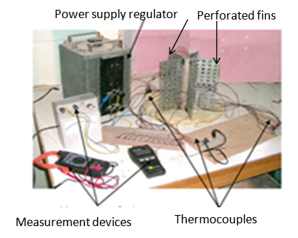 | Figure 1. Experimental setup [12] |
|
3. Finite Element Methodology
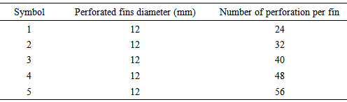
- The step by step procedure used in thermal analysis using ANSYS Finite Element Analysis (FEA) package is presented in Figure 2. Model is created using Solid Works modelling software. Dimensions are same as the experimental setup of source data [12]. In the model five rectangular fins with different number of circular perforations are arranged in rectangular array. The created model in Solid Works is imported to ANSYS. A good quality hexa-mesh is performed. An overall mesh density of 2mm is chosen for better accuracy. Conduction is modelled using SOLID70 element and surface convection is modelled using SURF152 element available from ANSYS element library. The different iterations considered in the analysis are presented in Figure 3.
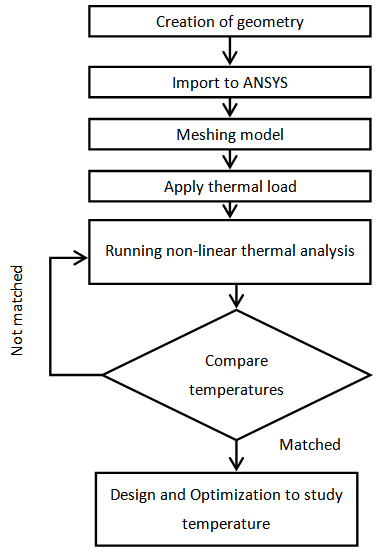 | Figure 2. Steps in thermal analysis |
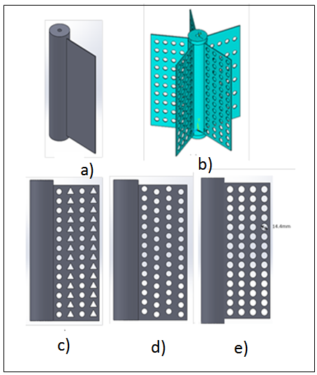 | Figure 3. Configurations considered in FEA study. (a). Solid fin (non-perforated), (b). Number of circular perforations, (c). Mixed perforations (d). Triangular pitch design, (e). Increasing hole diameter |
4. Results and Discussion
4.1. Effect of Number of Perforations
- Thermal contour results for a typical case of a plate with 56 perforations and 90W power input is presented in Figure 4. It is clear from the contour results that temperature drops from the fin base towards the tip. The comparison between experimental results and FEA results in case of the plate with 56 perforations is shown in Figure 5. The secondary Y-axis indicates the difference in the values between experimental and FEA (ANSYS). It can be noted that the results are in close agreement and the maximum percentage deviation is well within -10%. On comparison of results for other cases, it was observed that the maximum deviation was within ±10%.
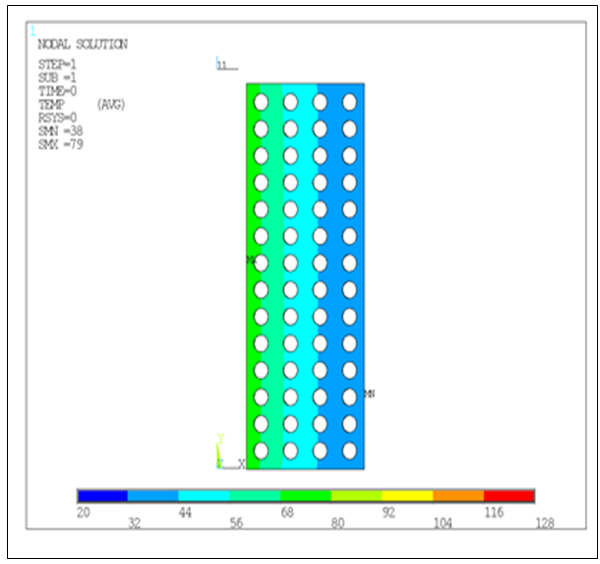 | Figure 4. Thermal contour in a plate of 56 holes for 90W power |
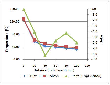 | Figure 5. Comparison between experimental and FEA result |
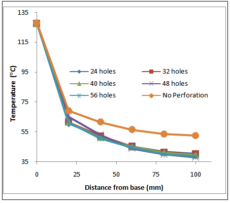 | Figure 6. Temperature distribution in non-perforated and peforrated fins |
4.2. Effect of Change in Pitch Design
- Effect of changing the pitch design on the temperature distribution is indicated in Figure 7. It presents the case of 56 holes plate for 40W power input. As it can be observed from the Figure 7, there is no much change in the variation of the temperature. Thus changing the hole pitch did not show any improvement in the thermal performance of the fins in the present case.
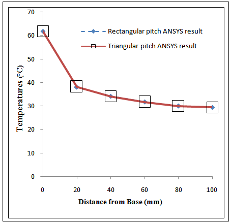 | Figure 7. Effect of change in pitch design on temperature distribution |
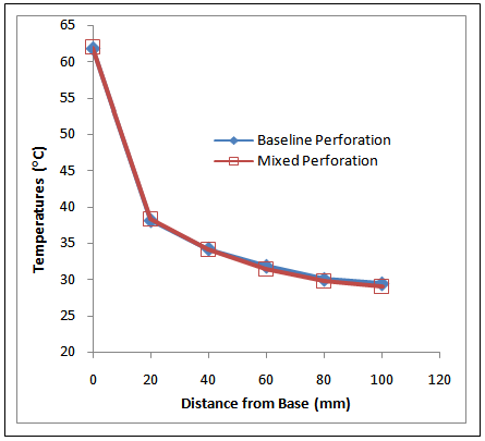
4.3. Effect of Mixed Perforations
- Figure 8 shows comparison of finite element temperatures between base line perforations and mixed perforations. In the present analysis, it is observed that temperatures of mixed perforations are less than the base line perforations by very small amount. As triangular and circular perforation has equal cross-sectional areas, there is no much change in the temperature observed.
 | Figure 8. Effect of mixed perforations on temperature distribution |
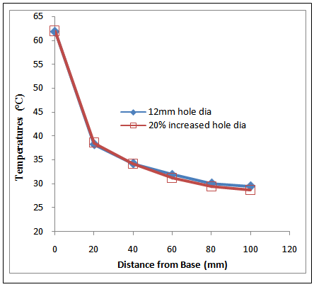
4.4. E3ffect of Increasing Diameter
- As indicated in Figure 9, the increase in the hole diameter has obviously resulted in temperature drop. This is because of increased cross-sectional area which in turn increases the influence of convection. For an input power of 40W, the drop in the temperature is small in magnitude. However, temperature drop will obviously increase for higher input power levels and this iteration gives direction for further work.
 | Figure 9. Effect of increasing hole diameter on temperature distribution |
5. Conclusions
- The modelling and analysis of fins with different perforations was successfully done using finite element technique. Thermal contact phenomenon is modelled in a more realistic manner in-line with experimental setup. Based on the analysis and observations the following conclusions can be drawn.• The temperature distribution results by finite element analysis matched well with experimental observations in the literature and the maximum deviation was within ±10%. • The finite element analysis also indicated that perforated fins show considerable reduction in temperatures compared with non-perforated fins.• Changing the hole pattern from rectangular to triangular pitch did not show any influence on the fin temperatures.• Changing the circular perforations with combination of alternatively arranged circular and triangular perforations with equivalent cross sectional area did not improve the thermal performance. • Increasing the circular perforation diameter is found to reduce the fin temperature. The quantitative difference is found to depend on the base temperature or input heating power. The finite element analysis procedure established in the present study can be used for the thermal analysis of fins with different fin parameters.