-
Paper Information
- Next Paper
- Previous Paper
- Paper Submission
-
Journal Information
- About This Journal
- Editorial Board
- Current Issue
- Archive
- Author Guidelines
- Contact Us
American Journal of Materials Science
p-ISSN: 2162-9382 e-ISSN: 2162-8424
2015; 5(3C): 30-33
doi:10.5923/c.materials.201502.06
Experimental Investigation on Fracture Toughness of Cu-Al-Be Shape Memory Alloy
 Abstract
 Reference
 Full-Text PDF
 Full-text HTML
Prashantha S. 1, Kalinga T. 2, N. Manjunath Gowda 2, Mallik U. S. 1, S. M. Shahshidhara 3
1Department of Mechanical Engineering, Siddaganga Institute of Technology, Tumkur, Karnataka, India
2Department of Mechanical Engineering, UBDTCE, Davanagere, Karnataka, India
3Department of Mechanical Engineering, Sridevi Institute of Engg. & Technology, Tumkur, Karnataka, India
Correspondence to: Prashantha S. , Department of Mechanical Engineering, Siddaganga Institute of Technology, Tumkur, Karnataka, India.
| Email: |  |
Copyright © 2015 Scientific & Academic Publishing. All Rights Reserved.
Fracture toughness of Cu-Al-Be shape memory alloys (SMA’s) is determined by using circumferentially notched round bar (CNRB) alloy specimens. Three different compositions of Beryllium (0.42, 0.45 and 0.47 wt. %) in Cu-Al-Be SMA’s are prepared by ingot metallurgy. Fracture toughness of CNRB specimens is investigated through uniaxial tensile loading (Mode-I type). This paper explains the determination of fracture toughness as a measure of stress intensity factor (SIF) and strain energy release rate (SERR). Four kinds of crack lengths are generated to examine the effect of notch configuration on SIF (KIC) and SERR (GIC) of SMA samples. Addition 0.47 wt. % of beryllium content shows higher fracture toughness value as compared to other two compositions. Stress intensity factor increases and Strain energy release rate decreases with increase in Crack length.
Keywords: Fracture toughness, Shape memory alloy, Cu-Al-Be, CNRB, Crack lengths, KIC, GIC
Cite this paper: Prashantha S. , Kalinga T. , N. Manjunath Gowda , Mallik U. S. , S. M. Shahshidhara , Experimental Investigation on Fracture Toughness of Cu-Al-Be Shape Memory Alloy, American Journal of Materials Science, Vol. 5 No. 3C, 2015, pp. 30-33. doi: 10.5923/c.materials.201502.06.
Article Outline
1. Introduction
- Shape memory alloys are the unique group of metallic materials, which have the ability to recover their pre-defined crystallographic configuration from large deformations when subjected under appropriate thermo-mechanical cyclic loadings without the residual strain. SMA’s exhibits two distinct properties namely shape memory effect (one way memory effect or two way memory effect) and pseudoelasticity. These unique properties of SMA’s have found increasing applications as in medical devices, mechanical actuation systems, industrial automation, MEMS components, aerospace, marine industries and defence [1-3]. Many researchers studied the shape memory effect, pseudoelastic effect, phase transformation temperatures (i.e. Ms, Mf, As, and Af), microstructure, damping effect and corrosion resistance of the Nitinol and Cu-based shape memory alloys like Cu-Zn-Ni, Cu-Al-Ni, Cu-Al-Mn, Cu-Al-Be, etc. During recent years Cu-based SMA’s have been extensively investigated because of their good shape memory effect and pseudoelasticity, low production cost and easy to manufacture [4, 7]. Nevin Balo et al. (2009) [2] and Prashantha et al. (2014) [3] reported that the addition of little amount of the beryllium (Be) in the Cu-Al system shows good shape memory effect and increases the hardness of the alloy.Most experimental and modeling on the Cu-Al-Be shape memory alloys have focused on the thermo-mechanical deformation characteristics and their micromechanisms [1, 7]. Fracture failure is one of the important design considerations in all the structure or component design. The fracture toughness is a generic term used for measure of the material’s resistance to extension of a crack or a flaw and is an essential reference parameter used in structure or component design to avoid catastrophic fracture failure [8, 9]. The fracture toughness measurement is based on the Stress Intensity Factor (KIC) of the test specimen. The ASTM E399 standard test method is one of the accurate method to measure the Fracture toughness (KIC) of any material having standard pre-cracked specimens of different geometries such as Single Edge Notched Bend (SENB) or Compact Tension (CT) specimens. These methods are however difficult to perform and specimen preparation procedure is also tedious [11]. Therefore the circumferential notched round bar tension specimen geometry was proposed by the researchers R N Ibrahim et al. (2000) [9], Neelakantha V Londe et al. (2010) [10] and S K Nath et al. (2006) [11] to determine the valid and reproducible KIC of the metallic materials from simple mechanical properties. In the present work, fracture toughness Cu-Al-Be SMA round bar was determined by uniaxial tensile loading.
1.1. Determination of Fracture Toughness (KIC and GIC)
- Fracture toughness is a measure of the ability of a material to resist the growth of a pre-existing crack or flaw. This parameter is used extensively to design fracture safe structures. To do fracture mechanics analysis, the stress intensity factor (SIF) and strain energy release rate (SERR) are to be determined for the geometry of interest as shown in Fig. 1.
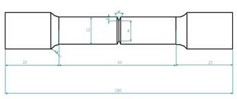 | Figure 1. Standard geometry for fracture test specimens |
1.2. Stress Intensity Factor Approach
- In Linear-Elastic Fracture Mechanics (LEFM) the critical stress intensity factor characterizes the fracture toughness of the materials. The stress intensity factor (SIF) is the magnitude of the crack tip stress field for a particular mode in a homogeneous linear elastic material. Usually denoted by KI. According to this approach stress state at the tip of a crack is proportional to the stress intensity factor. Under tensile loading, unstable crack growth occurs when KI attains a critical (KIC) value and this causes failure of the components and this parameter is used as an alternative measure of fracture toughness. The expression used for determining KIC of circumferential notched round bar tension specimen [8, 10, 11] is given below:
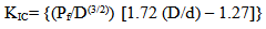 | (1) |
1.3. Compliance Calibration Method
- The energy approach states that, the crack extension occurs when the energy available for crack growth is sufficient to overcome the resistance of the material. The strain energy release rate (GI) is the crack driving force in Mode-I condition. Compliance of the material is measured for each crack length and by this values the critical value of energy release rate (GIC) is calculated. This causes the crack propagation to fracture. GIC is called the fracture toughness of the material (i.e., material resistance to fracture) and it is determined by using following expression [12],
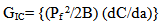 | (2) |
2. Experimentation
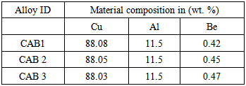
- In this work 11.5 wt.% of aluminium, 0.42-0.47 wt.% of beryllium and rest of the copper are chosen for the fabrication of Cu-Al-Be shape memory alloys (SMA’s). Cu-Al-Be Shape memory alloys with composition given in Table. 1. were prepared using an induction furnace. The compositions of the cast alloys were determined using Perkin Elmer Integrally coupled Plasma-Optical Emission Spectrophotometer(ICP-OES) which is capable of determining the compositions upto the second decimal place. For compositional analysis, 1 gram of the alloy sample taken from middle portion of the homogenised ingots. The alloy specimens were prepared by using right quantities of the small pieces of pure copper, aluminium and beryllium cut from the respective metal ingots by using lever shear machine. In graphite crucible 200 gram of pieces of material are melted under inert atmosphere. After melting alloy was poured into a preheated cylindrical holed cast iron die mould of dimensions 16 mm x 13 mm (diameter x height) and allowed to solidify under gravity pressure. After solidification, the specimens were taken out from the cast iron die mould and heated at constant temperature (~900°C) for the duration of 4 hour in a Muffle furnace to obtain a completely homogenized alloy. Homogenized alloy specimens were then machined according to the ASTM standards. The specimens were subjected to betatization for 30 minutes at 900°C and then step quenched into hot water (~ 100°C) and cold water at room temperature(~ 30°C). The different geometry of circumferential V-notch have been done on betatized specimens. The prepared samples tested for fracture toughness by tensile loading.
|
3. Results and Discussion
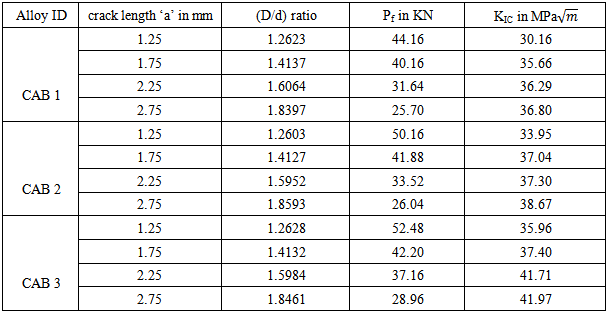
- The pre-cracked specimens were subjected to tensile loading to determine the fracture toughness as a measure of stress intensity factor (KIC) and strain energy release rate (GIC) in Mode-I condition. Three alloy compositions with four different crack geometry of interest was chosen for each composition, which are loaded under uniaxial tensile loading till fracture. After fracture failure the fracture load, Pf (i.e. load at break) and maximum deflection (δ) were recorded. The recorded fracture load data shows that, as the crack length increases the load bearing capacity decreases for all the alloy samples. These recorded data were utilized to calculate KIC and GIC which measures fracture toughness of the Cu-Al-Be shape memory alloys.
3.1. Stress Intensity Factor Approach
- Fig.2 illustrates the variation of KIC of all the three alloy compositions with different notch configurations. From the figure it is observed that, KIC value of all the three alloy compositions increases with increase in crack length. Addition of Beryllium content in little amount increases KIC value. CAB 3 alloy samples exhibit higher KIC value for same crack length as compared to other two compositions.
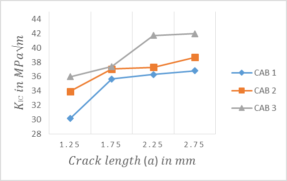 | Figure 2. Variation of KIC with crack length |
|
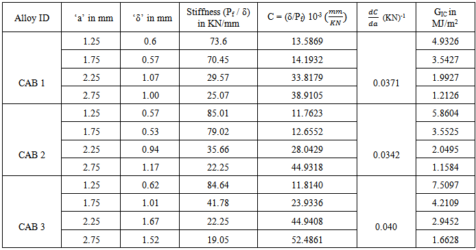
3.2. Compliance Calibration Method
- Compliance is a reciprocal of material stiffness. Therefore by knowing the stiffness the compliance can be determined (Table 3). Fig. 3 shows the variation of SERR (GIC) of all the three alloy compositions with different notch configurations. Figure illustrated as GIC value of all the three alloy compositions decreases with increase in crack length. Addition of Beryllium content in little amount improves strain energy release rate (GIC). CAB 3 alloy specimens exhibit higher GIC for same crack length as compared CAB 2 and CAB 1.
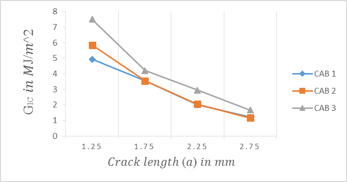 | Figure 3. Variation of GIC with crack length |
|
4. Conclusions
- • Stress intensity factor (KIC value) of all the three alloy compositions increases with increase in crack length and it has also shown dependency on Beryllium content present in the alloy sample. • Strain energy release rate (GIC value) of all the three alloy compositions decreases with increase in crack length. • Addition of Beryllium content in little amount occupies the vacancies existing in between the copper and aluminium intermetallic bonds and as a result of this increases Stress intensity factor (KIC) and Strain energy release rate (GIC).• CAB 3 alloy sample exhibit higher KIC and GIC value for same crack length as compared to other two compositions.