Vijay V. S., Aravinda Bhat K., Sachin Shetty, Gurudatta N. V., Russell Sequeira
Department of Mechanical Engineering, St. Joseph Engineering College, Mangaluru, India
Correspondence to: Vijay V. S., Department of Mechanical Engineering, St. Joseph Engineering College, Mangaluru, India.
| Email: |  |
Copyright © 2016 Scientific & Academic Publishing. All Rights Reserved.
This work is licensed under the Creative Commons Attribution International License (CC BY).
http://creativecommons.org/licenses/by/4.0/

Abstract
Internal combustion (IC) engine is one of the most important prime movers driving many of the automobiles today. Improving efficiency and reducing energy losses is the focus of research in IC engines. It is a known fact that exhaust gas from an internal combustion engine carries away about 30% to 40% of the heat of combustion. The energy available in this exit stream of exhaust gases goes as waste, if not utilized properly. This paper presents a concept of recovering waste heat energy of exhaust gas of diesel engine by placing a heat exchanger in the exhaust manifold so that energy from the exhaust gases can be used for preheating fuel. Initially a simple concentric tube type design is used to estimate the temperature of fuel by utilizing energy from exhaust gases. Based on the output obtained from this initial design, a shell and tube heat exchanger is fabricated for diesel engine to recover waste heat from exhaust. Maximum fuel temperature achieved for concentric tube heat exchanger is 133°C at 25% of full load at 1500 rpm. For shell and tube heat exchanger, 73°C and 90°C of fuel preheat temperatures are achieved for parallel and counter flow arrangements at 50% of full load at 1500 rpm. Effectiveness of heat exchanger is found to be 75% for parallel flow and 81% counter flow. Waste heat recovered at 50% full load condition is found to be 48.5% for parallel flow and 72% for counter flow arrangements respectively. Preheating fuel using heat exchanger is very much useful for biodiesel application in diesel engines.
Keywords:
Heat exchanger, Exhaust gas, Waste heat recovery, Preheat, Effectiveness
Cite this paper: Vijay V. S., Aravinda Bhat K., Sachin Shetty, Gurudatta N. V., Russell Sequeira, Design and Fabrication of Heat Exchanger for Waste Heat Recovery from Exhaust Gas of Diesel Engine, Journal of Mechanical Engineering and Automation, Vol. 6 No. 5A, 2016, pp. 131-137. doi: 10.5923/c.jmea.201601.25.
1. Introduction
Energy conservation is the need of the hour today due to the large gap which still exists between its demand and supply. This is also applicable to Internal Combustion Engines where about 60% to 65% of thermal energy is wasted without getting converted into useful work. In this regard, recovering waste heat from exhaust gases of engines is found to be very promising method. In this work, a heat exchanger is used in the exhaust manifold to recover waste heat of the exhaust gases to preheat fuel which is injected into the combustion chamber. Objectives of this work are stated as follows. 1. To design a heat exchanger for stationary engines, so that exhaust waste from them can be used for any other purposes.2. To study effectiveness of heat exchanger, temperature of preheated diesel and amount of waste heat recovered for different designs.Several research works are under way in the area of waste heat recovery from the exhaust gases of IC engines. Alberto A. Boretti [1] used Organic Rankine Cycle (ORC) system to recover waste heat from exhaust gases which increased the usable power versus the fuel energy flow rate to 3.4% on average, with top improvements up to 6.4%. The two combined ORC permit to increase the usable power versus the fuel energy flow rate of a 5.1% on average, with top improvements up to 8.2%.V. Pandiyarajan et al. [2] used a shell and finned tube heat exchanger integrated with an IC engine setup to extract heat from the exhaust gas and a thermal energy storage tank used to store the excess energy available is investigated in detail. A combined sensible and latent heat storage system is designed, fabricated and tested for thermal energy storage using cylindrical phase change material (PCM) capsules. The effectiveness of the heat recovery heat exchanger approaches nearly 99% at the end of charging process at all load conditions. Nearly 10–15% of total heat is recovered with this system. By decreasing the exhaust gas temperature below 100ºC it is possible to recover the heat which is liberated from the fuel along with the exhaust gas during the burning of fuel.Mr. Janak Rathavi et al. [3] presented the experimental results for significant reduction of engine fuel consumption and hazardous emissions by recovering of exhaust heat by using self-made Heat Exchanger. Brake Thermal Efficiency on 27° injection timing by the mixing of diesel vapour mixture fuel with air after pre-chamber Direct Port Supply (DPS), the percentile increment of the brake thermal efficiency with loads of 100%, 75%, and 50% was 19.8%, 12.17%, and 14% respectively. BSFC decreased by 5.44% for 27° IT, 15% for 30° IT and 14% for 27° IT with DPS at 50% to 100% load.José Manuel Luján et al. [4] worked on experimental facility implemented with the aim of improving the performance of internal combustion engines working at low ambient temperatures. In this work, an exhaust heat recovery system for a diesel engine has been proposed as a solution to cold operation negative effects. The energy obtained from the exhaust gases was used to increase the intake air temperature. In order to analyse the effect of the heat recovery system, the experiments with an in line 4 cylinders, 2.0 l, turbocharged HSDI diesel engine were conducted. Engine Intake manifold is replaced by a water/air heat exchanger, known as Water Charge Air Cooler (WCAC) that is joined to a short intake manifold. Intake air heating results with the heat recovery system shows a 10% in fuel use compared to standard air–air intercooler.Sheikh. N. Hossain, S. Bari [5] performed experiment to calculate the available energy in the exhaust gas of an automotive diesel engine. A shell and tube heat exchanger was used to extract heat from exhaust gas and performance of two shell and tube heat exchanger was investigated with parallel flow arrangement using water as a working fluid. Maximum temperature was found to be 747°C at maximum power of 45.39KW. The maximum specific energy was found to be 438kJ/kg at engine speed of 2200 rpm. The maximum pressure drop across optimized heat exchanger was found to be 30.3kPa and 0.5% of power was lost due to pressure drop across heat exchanger. The maximum power output of 8.61kW was achieved at 30bar working pressure. At 30 bar pressure the proposed heat exchanger could recover 20.6% additional power from exhaust of diesel engine.Roland Strahle et al. [6] worked on an exhaust gas heat exchanger including a stack of heat exchanger plates that form separate flow channels that run parallel to each other, collection spaces, and inlets and outlets for the exhaust gas and for the preferably liquid coolant. The heat exchanger plates have edges that are bent to one side over the entire length of the plates. Preferably, the outer flow channels are intended for the coolant, because the radiant heat of the heat exchanger can be kept more limited on this account. At exhaust gas temperatures of 700°C and more, this makes a not insignificant contribution to reducing engine heating, especially in engines in the encapsulated design.Emanuel Feru et al. [7] presented paper on the modelling and model validation for a modular two-phase heat exchanger that recovers energy in heavy-duty diesel engines. The model is developed for temperature and vapour quality prediction and for control design of the waste heat recovery system. In the studied waste heat recovery system, energy is recovered from both the exhaust gas recirculation line and the main exhaust line. The recovered exhaust heat is converted to mechanical power, by means of a piston expander. The piston expander and pumps are mechanically coupled with the engine crankshaft. As a result, the recovered power is directly transmitted to the driveline. The plates are vertically aligned and connected with fins. In this study, the modular heat exchanger was described in detail based on the mass and energy balance equations.Feng Yang et al. [8] worked on the feasibility of using heat pipe heat exchangers and the calculation method is developed. Practical heat pipe heat exchanger is set up for heating a large bus. Simple experiments are carried out to examine the performance of the heat exchanger. It is shown that the benefit of exhaust gas heating, are in good agreement with numerical results. The hot fluid channel inlet of the heat exchanger was connected with the muffler outer of the bus. A fan with 100 mm water pressure head, 400 m3/h volume flow rate and 120W power was adopted to blow the air over the heat exchanger. The ambient temperature was 8°C. For hot fluid temperature of 300°C inlet and 164°C outlet, cold fluid temperatures of 8°C and 70°C is obtained. The heat transfer was found to be 6490W.
2. Experimental Methodology
The engine tests were conducted on single cylinder four-stroke diesel engine test rig, water cooled with a compression ratio of 16.5:1, running at a speed of 1500rpm with 5 HP rated power output. It was directly coupled to a rope brake dynamometer that permitted engine motoring fully or partially. Following is the methodology adopted.1. A simple concentric tube heat exchanger is used in the exhaust line as a preliminary design as shown in fig 1. Here the fuel pipe line is initially passed through the exhaust manifold and then connected to the fuel injector. T1 and T2 are exhaust gas temperatures before and after pre-heating. t1 and t2 are fuel temperatures at inlet and exit of heat exchanger. Engine is made to run at different loads and temperature of both fuel and exhaust gas is recorded. Here, exhaust gas flow rate is left uncontrolled. Injection timing is observed to be at TDC.2. It is observed in above tests that, at 6 kg load, exhaust temperature increased beyond 600°C and fuel temperature crossed 130°C and made difficult to control the engine running. Therefore, it is decided to control the exhaust gas flow rate and modify the heat exchanger type from simple concentric type to shell and tube type. Fig 2 below shows modified experimental setup. Here heat exchanger is not fixed directly in exhaust gas line. Two valves are used and both are regulated in combination to control exhaust gas flow rate so that preheat temperature is properly controlled. Initially parallel flow arrangement is used where both exhaust gas and fuel flow in same directions. Here the fuel injection timing is kept at 23°C BTDC which is changed from earlier timing i.e. exactly at TDC, to know the effect of injection timing on preheat temperature.3. In the last arrangement, counter flow arrangement used as shown in fig 3. Here fuel flows in the tube in opposite direction to exhaust gas. Also only one valve is used to control mass flow of exhaust gas.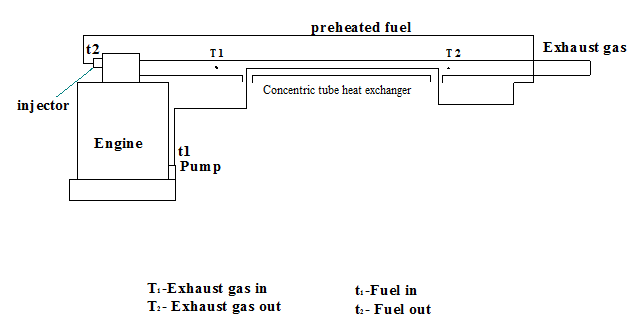 | Figure 1. Experimental setup with Concetric tube heat exchanger |
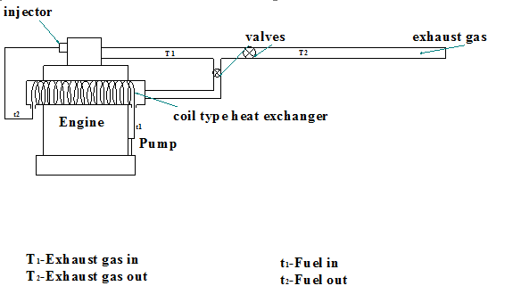 | Figure 2. Experimantal setup with shell and tube heat exchanger (parallel flow) |
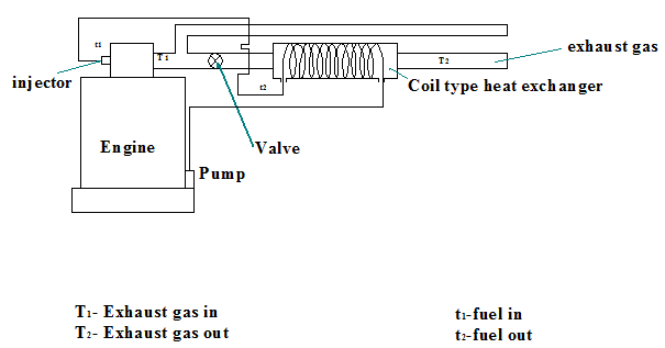 | Figure 3. Experimantal setup with shell and tube heat exchanger (counterflow) |
3. Design and Calculation
3.1. Waste Heat Recovery
Waste heat recovery represents the amount of waste heat of the exhaust gas absorbed by the fuel in the heat exchanger. It is obtained as percentage of waste heat recovered which is given by the ratio heat absorbed by fuel to heat carried away by exhaust gases. This is calculated as follows.Heat carried away by exhaust gas is given by 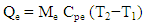 | (1) |
Where,Me = Mass of exhaust gas in kg/sec.Cpe = Specific heat of exhaust gas J/kg K.T2 = Exit temperature of gas °C.T1 = Inlet temperature of gas °C.Heat absorbed by the fuel is given by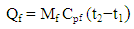 | (2) |
Where,Mf = Mass of fuel in kg/sec.Cpf = Specific heat of fuel in J/kg K.t2 = Exit temperature of fuel °C.t1 = Inlet temperature of fuel °C.Then, percentage of heat recovered can be calculated as, | (3) |
3.2. Effectiveness
Effectiveness of a heat exchanger is an important parameter which signifies ability of heat exchanger to transfer heat from hot fluid to cold fluid. In order to compare the performance of parallel flow and counter flow heat exchanger used in this experiment, this term is used as significant factor. In this case, effectiveness (∈) is calculated from the graph of ∈ vs NTU for 1-Shell Pass, 2, 4, 6 Tube Passes given heat transfer data hand book [9].NTU (Number of Transfer Units) can be calculated using the formula, | (4) |
Where,Cmin = Minimum capacity rate in J/sec KMh, Mc= Mass flow rate of hot and cold fluid, Kg/s. Cph, Cpc= Specific heat of hot and cold fluid, J/Kg KU= Overall heat transfer coefficient W/m2KA= Surface area of heat exchanger, m2 U is calculated using hi and ho i.e. heat transfer coefficients at inlet and outlet of tube which depends on coorelation of Nusselt number, Reynolds number and Prandtl number relation applied for internal flow through pipe and across the pipe considerations.Finally U is given by, | (5) |
3.3. Heat Exchanger Design
In this experiment, a shell and tube heat exchanger design is used. Shell is a tube connected to exhaust pipe of same diameter. So it is important here to design the tube length and number of turns for the tube. It is done as follows. We know that, heat transfer through heat exchanger is given by | (5) |
Where,Q = Heat exchanged, WU = Overall heat transfer coefficient W/m2KA = Area (m2) LMTD= Logarithmic Mean Temperature Difference LMTD for parallel flow and counter flow is given below,For parallel flow, | (6) |
For counter flow,  | (7) |
Then area A required for heat transfer can be calculated by | (8) |
 To determine Number of Turns required, the formula used is,
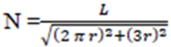 | (9) |
Where,N = Number of turnsL= Length of the tube.r = Radius of the shell.
4. Results and Discussion
The results obtained during preliminary test and main tests are presented here. Along with this, an estimation of amount of waste heat recovered and the effectiveness is also done for both parallel and counter flow arrangements.
4.1. Simple Concentric Tube Heat Exchanger
Figure 4 shows temperatures of fuel and exhaust gases at different engine loadings for simple concentric tube type heat exchanger. From the graph it is clear that as load is increased, temperature of fuel increased from 79°C to 133°C. Exhaust gas temperature also increased simultaneously from 255°C to 503°C. When load is increased beyond 4 kg exhaust gas temperature increased abnormally resulting in uncontrolled combustion of the engine.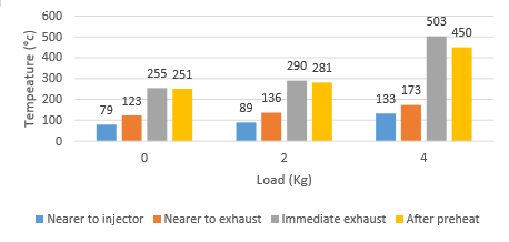 | Figure 4. Graph of temperature distribution |
The reason for increase in exhaust gas temperature along with fuel temperature could be due to extended combustion process till the end of exhaust stroke. For this reason, the injection timing of fuel is monitored by which it came to know that injection timing is at TDC. Therefore it was decided to advance injection timing to 23° BTDC which is a standard for given diesel engine.
4.2. Results for Shell and Tube Heat Exchanger
Figure 5 shows temperature variation of preheated fuel with parallel and counter flow arrangement. The preheated fuel temperature at maximum load for parallel flow found to be 73°C and for counter flow is 90°C respectively.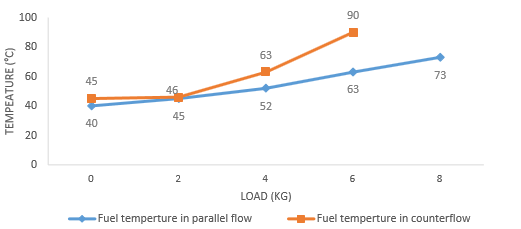 | Figure 5. Preheated fuel temperature vs Load |
From the graph it is clear that counter flow heat exchanger is more effective than parallel.
4.3. Waste Heat Recovered
Since the objective is to determine waste heat recovery from the engine. Waste heat recovered is the ratio of heat absorbed by fuel (Qf) in the heat exchanger to the heat available in the exhaust gas (Qe) at the given load conditions. In figure 6, normal condition indicates heat available in the exhaust gas (Qe) and red lines indicates heat absorbed by the fuel for both parallel and counter flow arrangements. It is observed that at 4kg and 6 kg load heat absorbed by fuel is higher for counter flow heat exchanger.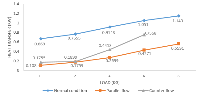 | Figure 6. Graph of heat transfer vs load |
Figure 7 below shows heat recovered in percentages for both parallel and counter flow arrangements. It is found that waste heat recovered for counter flow is more than that for parallel flow at same loading. This is mainly due to higher fuel temperature achieved in counter flow heat exchanger for the same engine loading than parallel flow type. 75% heat is recovered in counter flow as against 40.63% in parallel flow type for 6 kg load at 1500 rpm. 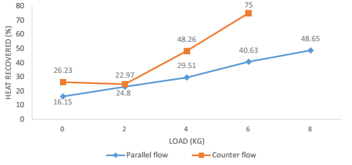 | Figure 7. Percentage Heat Recovered vs load |
4.4. Effectiveness
Effectiveness of heat exchanger is calculated by considering full load conditions. In this case maximum load applied is 6 kg which is 50% of full load. It is calculated by using effectiveness-NTU graph [9] which is based on capacity ratio and temperatures of both hot and cold fluids. It is found that effectiveness for parallel flow is 75% and for counter flow 81%.
5. Conclusions
In this work it is found that use of heat exchanger is a useful and simple method to utilize the waste heat energy available in the exhaust gas of diesel engine. Here shell and tube heat exchanger design is used with both counter and parallel flow arrangements. Following conclusion can be drawn from the experimental results:1. Fuel preheat temperature depends on flow rate of exhaust gas.2. In concentric tube type heat exchanger, fuel temperature obtained is in the range of 79°C to 133°C for loads ranging from 0 kg to 4 kg at 1500rpm where the flow rate of exhaust gas was uncontrolled. 3. In shell and tube heat exchanger, fuel preheat temperature is from 40°C to 73°C for parallel flow and for counter flow is from 45°C to 90°C for the loads ranging from 0kg to 8kg at 1500rpm by controlling mass flow rate of exhaust gas. 4. Effectiveness of heat exchanger is calculated by considering full load conditions. It is found that effectiveness for parallel flow is 75% and for counter flow 81%. 5. Waste heat recovered at 50% full load condition is found to be 48.5% for parallel flow and 72% for counter flow arrangements.6. Waste heat recovered for counter flow is more than that for parallel flow at same loading. Hence waste heat recovery is good in counter flow compared to parallel flow.
6. Scope of the Work
Scope of this work lies in efficient and compact design of heat exchanger. This method of preheating is very useful in use of biodiesel in diesel engines, where it is already known that preheating will reduce its viscosity and results in improved engine performance.
References
| [1] | Alberto A. Boretti, “Energy recovery in passenger cars”, Journal of Energy Resources Technology, ASME, June 2012, Vol. 134 / 022203-1. |
| [2] | V. Pandiyarajan, M. Chinna Pandian, E. Malan, R. Velraj, R.V. Seeniraj, “Experimental investigation on heat recovery from diesel engine exhaust using finned shell and tube heat exchanger and thermal storage system”, Applied Energy, 88 (2011) 77–87. |
| [3] | Mr. Janak Rathavi, Mr. Amitesh Paul, Dr. G.R. Selokar, “Experimental study of waste heat recovery technique to increase efficiency and to decrease hazardous emissions in C.I engine”, IJCER, Jan-Feb 2012, Vol. 2, Issue No.1. |
| [4] | José Manuel Luján et al., “Potential of exhaust heat recovery for intake charge heating in a diesel engine transient operation at cold conditions”, Applied Thermal Engineering, Jan 2016, Vol. 66-67, p862. |
| [5] | Shekh N. Hossain, S. Bari, “Additional power generation from waste energy from diesel engine using parallel flow shell and tube heat exchanger”, Journal of Engineering for Gas Turbines and Power ASME Vol. 136 / 011401-1. |
| [6] | Roland Strahle, Wolfgang Knecht, Viktor Brost, “Exhaust gas heat exchanger”, US Patent 6293227, July 23, 1999. |
| [7] | Emanuel Feru, Bram de Jager, Frank Willems, Maarten Steinbuch, “Two-phase plate-fin heat exchanger modelling for waste heat recovery systems in diesel engines”, Applied Energy, Volume133, 15 November 2014. |
| [8] | Feng Yang, Xiugan Yuan, Guiping Lin, “Waste heat recovery using heat pipe heat exchanger for heating automobile using exhaust gas”, Applied Thermal Engineering 23, 2003, 367–372. |
| [9] | C P Kothandaraman & S Subramanyan, Heat and Mass Transfer data hand book, New Age International Publisher, 2014. |

 Abstract
 Reference
 Full-Text PDF
 Full-text HTML