-
Paper Information
- Next Paper
- Previous Paper
- Paper Submission
-
Journal Information
- About This Journal
- Editorial Board
- Current Issue
- Archive
- Author Guidelines
- Contact Us
Journal of Mechanical Engineering and Automation
p-ISSN: 2163-2405 e-ISSN: 2163-2413
2016; 6(5A): 126-130
doi:10.5923/c.jmea.201601.24

An Experimental Study on Enhancement of Convective Heat Transfer over Dimpled Surfaces
Prashanth Kamath, Paramashivaiah M. Buksagamath, Niranjan Rai, Srinath N. Salian
Department of Mechanical Engineering, Canara Engineering College, Mangalore, India
Correspondence to: Niranjan Rai, Department of Mechanical Engineering, Canara Engineering College, Mangalore, India.
| Email: |  |
Copyright © 2016 Scientific & Academic Publishing. All Rights Reserved.
This work is licensed under the Creative Commons Attribution International License (CC BY).
http://creativecommons.org/licenses/by/4.0/

In a Vortex Heat Transfer Enhancement over a surface with an array of surface cavities or dimples each dimple acts as a vortex generator. The array of dimples causes an enhancement in heat transfer over a surface. The vortex provides an intensive and stable heat transfer and air flow between the dimpled surface and heat transfer media. In the present work, an experimental study of heat transfer through a flat surface with arrays of circular dimples was compared with the plane surface. The flow characteristics like Reynolds number (Re), Nusselt Number (Nu), and heat transfer characteristics like convective heat transfer coefficient (h), heat transfer rate (Q) on a forced convection apparatus was measured. The study was carried out for flat metallic surfaces without dimples and compared with dimpled flat surfaces. An array of dimples of 4x4 and 7x7 were prepared onaluminum, copper and stainless steel plates. The study was done for different air stream velocity and plate surface temperatures. The comparative study of heat transfer with smooth surface and dimpled surface was done. The result reveals that an increase in heat transfer rate for dimpled surfaces with 4x4 arrays and 7x7 arrays. Hence it can be concluded that an increase in array of dimple enhances the heat transfer compared to smooth surface.
Keywords: Vortex, Dimple, Array, Reynolds number, Nusselt number
Cite this paper: Prashanth Kamath, Paramashivaiah M. Buksagamath, Niranjan Rai, Srinath N. Salian, An Experimental Study on Enhancement of Convective Heat Transfer over Dimpled Surfaces, Journal of Mechanical Engineering and Automation, Vol. 6 No. 5A, 2016, pp. 126-130. doi: 10.5923/c.jmea.201601.24.
Article Outline
1. Introduction
- The surface having number of depressions on it is known as dimpled surface. A dimpled heat transfer surface is used for transferring heat energy from either a hot fluid or hot object to a cooler fluid. Dimple enhances heat transfer from its surface for laminar air flow while the pressure drop is equivalent or smaller than that of the flat surface. These surfaces do indeed enhance thermal performance without the penalty associated with higher pressure drops. A tremendous amount of effort has been devoted for developing new methods to increase heat transfer from finned surface to the surrounding flowing fluid [1]. It has been found that the heat transfer coefficient and heat transfer rate increases for dimpled surface as compared to plane surface. Dimples are used on the surface of internal flow passages because they produce substantial heat transfer augmentation. The importance of heat transfer enhancement has gained greater significance in such areas as microelectronic cooling, especially in central processing units, macro and micro scale heat exchangers, gas turbine internal airfoil cooling, fuel elements of nuclear power plants, and bio medical devices. The dimples formed on a surface can significantly enhance the heat transfer rate. Some of the examples are, heat transfer increase in cooling of turbine blade, tube and shell type heat exchangers in process industries like chemical and textile industries, radiators of automobiles etc.. Figure 1 shows flow velocity profile on vehicle’s centerline plane near the roof end, which causes the downstream pressure rise, which in turn generates reverse force against the main flow thus develops reverse flow at downstream point C. at point A no reverse flow take place which is located further upstream of point C. this is because the momentum of boundary layer is overcoming the pressure gradient between points A and C, there is separation point B, at which point there is an eqibalance between pressure gradient and the momentum of the boundary layer. In bottom zone nearer to the vehicle’s surface in the boundary layer, the air quickly loses the momentum when it moves downstream because of viscosity of air that results in reversal of air flow. The intension of adding the vortex generators is to provide the momentum from higher region where airflow has higher momentum compared to lower region where it has less momentum value. It is possible due to the stream wise vortices generated from vortex generators located just before the separation point, as shown in Figure 1. This permits separation point to move further downstream. Move in the separation point downstream makes the airflow to continue proportionately longer and flow velocity at the separation point become slower. Hence the static pressure becomes higher. The overall pressure in the entire flow separation region is governed by this static. This reduces the drag by enhancing back pressure. Shifting the separation point towards the downstream provides dual advantages in drag reduction, one is to narrow the separation region another is to raise the pressure of the flow separation region [2].
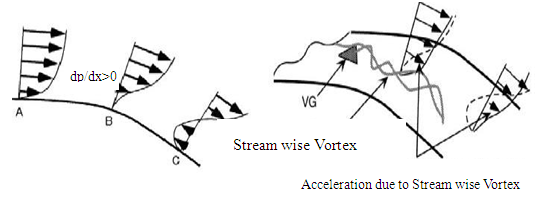 | Figure 1. a. Schematics of vortex generator b. Flow velocity profile around vortex at rear end |
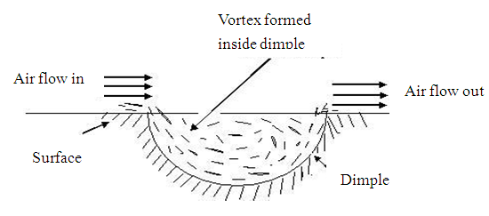 | Figure 2. Vortex heat transfer enhancement mechanism |
2. Materials and Experimental Details
2.1. Materials
- Test plates are of aluminium, Copper and stainless steel sheets of 2mm thickness and 100 mm × 100 mm length and breadth. The dimples produced are hemi-spherical inline dimples of depth 2 mm and 5mm diameter. For rectangular pattern arrangement total number of rows is employed in the stream wise direction Figure 3 shows different types of combinations of test plates.
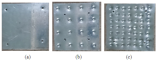 | Figure 3. Test surfaces (a) Flat surface (b) Test Surface with 4x4 array of dimples (c) Test Surface with 7x7x dimples |
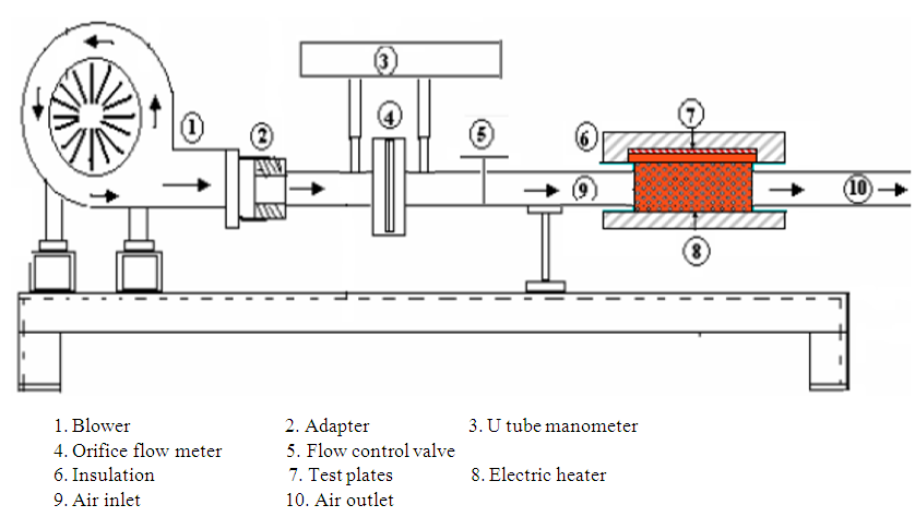 | Figure 4. Schematic diagram of the experimental setup |
2.2. Experimentation
- In the present work the individual test plates are mounted one by one in the test section. The test surfaces are placed in the middle of the test channel. Care is taken so that the test sheet can be located in the middle of the test section in order to ensure an equal channel height conditions and airflow rates for both sides of the test plate. The blower is turned on and air is forced through the test setup. The flow rate through the test section is controlled with the help of a valve. After the flow is set across the test section, the heater is turned on and the voltage supplied to the heater is set to desired output. As the temperature of the test sheet reaches steady state the pressure difference across the test section is checked using the manometer. The voltage supplied to the heater and the corresponding current is taken to calculate the heat supplied to the test sheet. The temperatures of the air at the inlet of test section and outlet section are determined. The temperatures at various points on the test plate are also checked using the temperature indicator. The same procedure is repeated for all test specimens.
3. Results and Discussion
- The data obtained after experimentation is used to tabulate the flow characteristics like Reynolds number and Nusselt number which shown in table 1, 2 and 3 for different materials. And further it is used to plot different flow and thermal characteristics. The figure 5 shows the variation of Reynolds Number with Nusselt Number for three different surfaces. It shows that Nusselt Number increases with increase in Reynolds Number as the density of dimples on surface is increased. It is found from the figure that for Aluminium plate with 7x7 array of dimples is having highest Nusselt Number, where as stainless steel is having minimum value for same dimple density. The figure 6 and figure 7 shows that variation of rate of heat transfer and percentage increase in heat transfer rate for three different test surface materials with different dimple densities. It is found that, as the dimple density increases, the rate of heat transfer increases for the different test surface materials. The percentage increase in rate of heat transfer over the flat surface for the 4x4 array and 7x7 arrays for stainless steel is 5.01 and 14.63 respectively. The percentage increase in rate of heat transfer over the flat surface for the 4x4 array and 7x7 arrays for Copper is 6.23 and 14.85 respectively. Whereas percentage increase in rate of heat transfer over the flat surface for the 4x4 array and 7x7 arrays for aluminium is 7.46 and 15.12 respectively. This results shows that the increase in rate of heat transfer is maximum for Aluminium surface with dimple density of 7x7 arrays. This is due to the increase in the Reynolds Number which leads to increased turbulence and strong vortex formation over the dimple cavities. The concept of decrease in thermal resistance and hence increase heat transfer is to increase the depth of the dimples. Providing the dimples on the surface enhances the surface area of heat transfer but also decreases the hydrodynamic resistance for the flow of fluid over the surface which results in decreased pressure drop. The vortices formed inside the dimples results in thinning and to disturb the thermal boundary layer formed over the surface during coolant flow and serve ultimately to bring about enhancement of heat transfer between the fluid and its neighboring surface at the price of less increase in pressure.
|
|
|
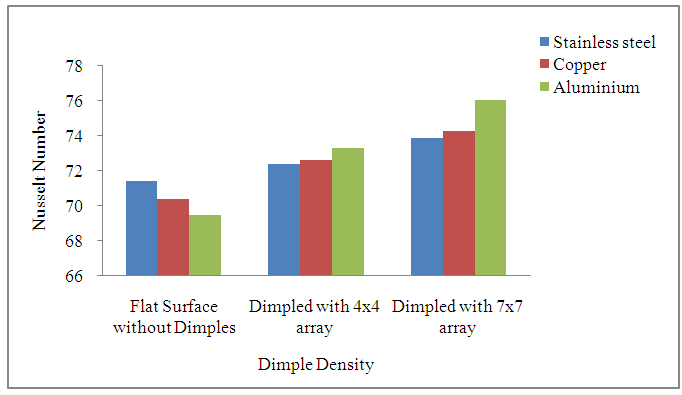 | Figure 5. Variation of Nusselt Number with Reynolds Number |
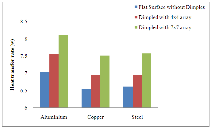 | Figure 6. Variation of Heat transfer rate (kJ) |
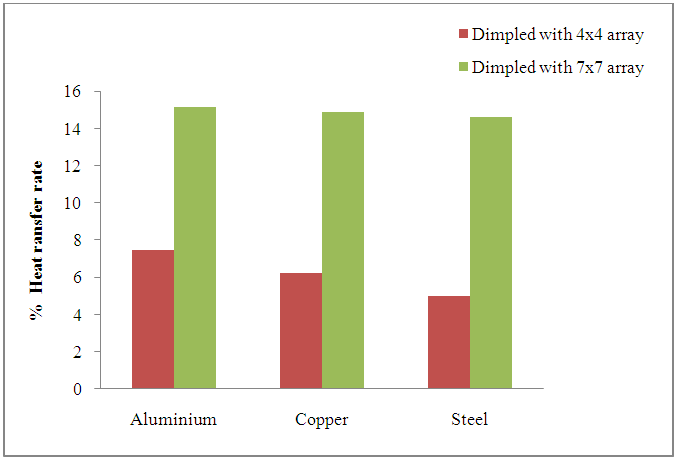 | Figure 7. Variation of Percentage of Heat transfer rate |
4. Conclusions
- The study concludes that more heat transfer enhancement on dimpled surfaces with lesser pressure drop penalty is obtained. Heat transfer rate from the test surface increases with increase in Reynolds number of flowing fluid and heat input. The use of dimples on the surface results in heat transfer augmentation in forced convection heat transfer with lesser pressure drop penalty. The more number of dimples increase the strength and intensity of vortices and associated secondary flows. The results shows an increase in heat transfer rate for dimpled surfaces with 4x4 array as 7.46%, 6.23% and 5.13% for Al, Cu and Stainless steel plates, where as it was 15.12%, 14.85% and 14.63% for 7x7 array compared to smooth surface.
 Abstract
 Reference
 Full-Text PDF
 Full-text HTML

