Ramyashree A. P.1, Joel A. Dmello2, Rakshith H. S.1, Impha Y. D.1, Mahammad Yunus C.1, Ajaygan K.1, Mustaqeem Raza1, Mohammed Imran M. A.1, Harsharaj K.1
1Department of Mechanical Engineering, SCEM, Mangalore, India
2Department of Mechanical Engineering, SJEC, Mangalore, India
Correspondence to: Ramyashree A. P., Department of Mechanical Engineering, SCEM, Mangalore, India.
| Email: |  |
Copyright © 2016 Scientific & Academic Publishing. All Rights Reserved.
This work is licensed under the Creative Commons Attribution International License (CC BY).
http://creativecommons.org/licenses/by/4.0/

Abstract
Energy is a basic requirement for the existence and development of human life. The energy demand in our day to day life is escalating significantly, but available energy lacks in supply. Hence there is no option for proper and efficient utilization and conservation of energy. Now a day's air conditioner is a banal device which occupies most of our castle for our comforts. The regeneration of low grade energies such as thermal energy into some beneficial work is a fantastic job. So it is imperative that a significant and concrete effort should be taken for using the thermal energy through waste heat recovery. Here the main stress is given on energy conservation by using the technique of utilizing the rejected heat from air conditioning system. On experimentation the COP is observed to increase by 6% on incorporating heat exchanger.
Keywords:
Waste heat, Heat recovery, COP
Cite this paper: Ramyashree A. P., Joel A. Dmello, Rakshith H. S., Impha Y. D., Mahammad Yunus C., Ajaygan K., Mustaqeem Raza, Mohammed Imran M. A., Harsharaj K., Heat Recovery from Air Conditioner, Journal of Mechanical Engineering and Automation, Vol. 6 No. 5A, 2016, pp. 113-116. doi: 10.5923/c.jmea.201601.21.
1. Introduction
Energy saving is one of the key issues not only in view point of energy conservation but also for the aegis of global environment. Waste heat is the heat generated all along most of the operations of system and then it is dumped into the surroundings even though it could be still utilized for some other beneficial and remunerative purposes. Waste heat is usually correlated with waste streams of air or water and it put into the environment. Air conditioning units remove heat from interior spaces and reject it to the ambient air. This increases environment temperature. All over world billions of AC is used which results in addition of enormous amount of heat to the atmosphere. So it is important to utilize that heat. This is done by designing a heat exchanger which extracts heat from hot air and in turn heats the water without affecting COP.M.Joseph Stalin et al [2] had shown that by replacing water cooled condenser in AC rescue 4 numbers of LPG gas Cylinders per year. R.B Lokapure et al [1] designed a heat exchanger which increased COP of the system by 13.66%. Sathiamurthi et al [3, 4] studied on waste heat recovery from an air conditioning unit that the energy can be recovered and utilized without affecting COP. In the past years, E.F. Gorzelnik [6] indulged in the recovery of energy in the heat of compression from air conditioning, refrigeration, or heat-pump equipment in 1977 itself. Kaushik and Singh [5] confabulated about 40 percent of heat is recovered using Canopus heat exchanger in 1995. Hung et al [14] discussed in a review of Organic Rankine Cycle for the feasibility of recovery of low grade industrial waste heat in 2000. M. Bojic [7] studied and explained the heat rise in environment due to heat rejected from Air Conditioners in 2001.
2. Description
In India, every individual is exposed to intense summer effects and all are longing to comfort. Hence one would aggrandize Air conditioning system. This Air conditioner rejects enormous amount of heat to the environment through air. So a water-air heat exchanger which extracts heat from air and heats the water is proposed to design. This hot water can be used in several places like hospitals, commercial buildings and residential areas for washing vegetables, cooking etc. This system consists of rectangular duct with centre hole, overhead tank, pipe lines for supply and delivering of hot water, regulating valve and storage tank with insulation.A window type air conditioning system consisting of air cooled condenser is taken for experimentation. Behind the condenser a rectangular duct is created with a hole at centre which bypasses the hot air. Duct is connected to the heat exchanger. One end of the heat exchanger is connected to overhead tank and other end to the storage tank via pipelines. Regulating valve is provided to control the flow rate of water.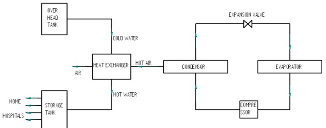 | Figure 1. Flow diagram of production of hot water system |
3. Working
The refrigerant enters compressor from evaporator by absorbing heat from hot air and cools it. Compressor compresses the refrigerant there by increases pressure and temperature. The high-pressure, high-temperature refrigerant enters the condenser and rejects heat to the atmospheric air there by temperature of the refrigerant reduces then it enters into the expansion valve. In expansion valve pressure reduces. And it enters into the evaporator and cycle repeats. The hot air which is coming out of the condenser is collected in rectangular duct. Then this hot air is made to flow through shell and tube Heat exchanger. In shell hot air is passed and in tube water. Tube is connected to over head tank and storage tank using pipelines. From overhead tank cold water enters tube there it absorbs heat from air and becomes hot. This hot water is stored in storage tank and used for other applications. This heating of water is done by extracting the waste heat coming out of the condenser. There by we can reduce the usage of LPG gas. This hot water can be used in Hospitals (to wash patient cloths), in cooking (to wash vegetables) etc.
4. Methodology
4.1. Duct Analysis
Duct is created behind condenser to guide the hot air which is coming out of condenser. This further connected to heat exchanger. So it is necessary to find out the Diameter and Position of hole.
4.1.1. Analysis Parameters
Diameter of duct hole, Position of the hole Conditions: Room temperature: 34°C, Pressure: Atmospheric pressure (101.325kpa) 
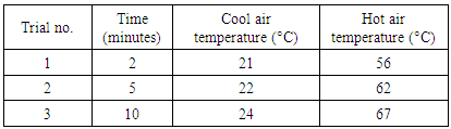
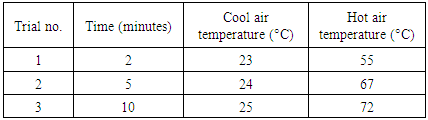
Table 1. Temperature of air for 2'' hole
 |
| |
|

Table 2. Temperature of air for 2'' hole
 |
| |
|

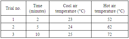
Table 3. Temperature of air for 2.5'' hole
 |
| |
|

Table 4. Temperature of air for 2.5'' hole
 |
| |
|
4.1.2. Conclusion of Duct Analysis
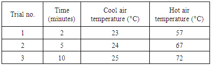
Ÿ With 2 inch central hole, minimum cool air temperature can be obtained and which is desired because at minimum value of cool air temperature, heat extracted will be maximum. This increases the performance.Ÿ Corner hole is not preferred because it causes back pressure and reduces the performance of AC.Ÿ From above observations it is concluded that 2'' central hole gives expected result.Table 5. Temperature of air for 2'' hole
 |
| |
|
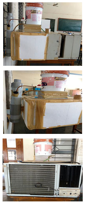 | Figure 2. Air conditioning system with heat exchanger |
4.2. Design of Heat Exchanger
By energy conservation principle,Heat lost by hot air = Heat gained by cold water i,e | (1) |
Where,Kcopper= Thermal conductivity of copper(dT/dX) = Temperature gradient (dT/dt) = Temperature variation w.r.to timeCP= Specific heat of hot airm= mass of hot airA= Area of copper tube | (2) |
Mass flow rate of air=Density of hot air * Volume flow rate Density of hot air at 56°C =1.0732 kg/m3 Mass flow rate of hot air=11.5289*10-3 kg/s
 | (3) |
 Therefore we can optimum nominal 3/8'' L type copper pipe.
4.3. To Calculate COP
4.3.1. COP without Heat Exchanger Input power to ac Unit = 2.5kW
To find the amount of heat extracted from the cooling space: Following observations were taken at the evaporator & by using Psychometric chart enthalpies are calculated:Table 6. Properties of air at inlet and outlet
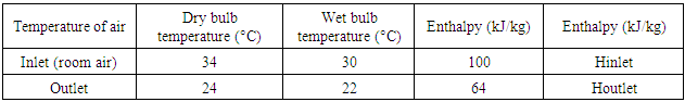 |
| |
|
 To find in terms of Watt, mass flow rate of outlet air (at cooling space) is needed.Mass flow rate of outlet air = Volume flow rate of outlet air*density Volume flow rate of outlet air = area * velocity of outlet air (at cooling space)
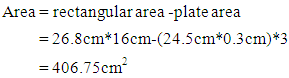 Velocity of outlet air = 6.18m/sVolume flow rate of outlet air = 0.2514m3/s Mass flow rate of outlet air = 0.2989kg/sHeat extracted from the cooling space = 10.7609kW Coefficient of performance = Refrigeration effect/Input power to acCoefficient of performance = 4.3044
4.3.2. COP with Heat Exchanger
We know that,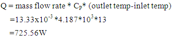 Hence,Coefficient of performance (COP) of a/c, with heat ex- changer, is given by = (10706.9+725.56)/2500 =4.5729
 Hence,With waste heat recovery system not only the waste heat can be recovered, but also the coefficient of performance of a/c system also can be increased.
5. Result and Discussion
5.1. Energy Balance
5.1.1. Without Heat Exchanger
Power rating of ac: 2.5kW Wattage of compressor: 1.4kWInput power = Compressor work + Waste heat 2.5kW = 1.4kW+Waste heatWaste heat = 1.1kWThis is amount of waste heat let out to the atmosphere from AC without heat exchanger.
5.1.2. With Heat Exchanger
Power rating of ac: 2.5kWWattage of compressor: 1.4kWInput power = Compressor work+ Waste heat + heatUtilized to heat water 2.5kW = 1.4kW + Waste heat + 0.726kWWaste heat=0.374 kWThis is amount of waste heat let out to the atmosphere from AC with heat exchangerFrom above results we can say that by incorporating waste heat recovery system with AC it recovers 66% of the waste heat that means; only 34% of the waste heat is let out to the atmosphere.
6. Conclusions
From the above experimental analysis following conclusions were made:Ÿ Thermal pollution is reducedŸ The COP of the system is increased by 6% by incorporating heat exchanger with AC.Ÿ Waste heat is utilized for useful purposeŸ Energy is conserved
References
| [1] | R.B. Lokapure1, J.D. Joshi, "Waste heat recovery through air conditioning system", International Journal of Engineering Research and Development, e-ISSN: 2278-067X, p-ISSN: 2278-800X, www.ijerd.com Volume 5, Issue 3 (December 2012), PP. 87-92. |
| [2] | M. Joseph Stalin, S. Mathana Krishnan, G. Vinoth Kumar, "Efficient usage of waste heat from air conditioner", International journal of advances in engineering &technology, July 2012. ISSN: 2231-1963. |
| [3] | P. Sathiamurthi, R. Sudhakaran “Effective utilization of waste heat in air conditioning". Proc. (2003) 13-14. |
| [4] | P. Sathiamurthi, PSS. Srinivasan, "Design and development of waste heat recovery system for air conditioner," European Journal of Scientific Research ISSN 1450-216X Vol.54 No.1 (2011), Pp.102-110. |
| [5] | S. C. Kaushik, M. Singh, “Feasibility and Refrigeration system with a Canopus heat exchanger”, Heat Recovery Systems & CHP, Vol.15 (1995)665 - 673. |
| [6] | E. F. Gorzelnik, "Heat water with your air-conditioner", Electrical World 188 (11) (1977) 54–55. |
| [7] | M. Bojic, M. Lee, F. Yik, "Flow and temperature outside a high-rise residential building due to heat rejection by its air-conditioners", Energy and Buildings 33 (2001) 1737–751. |
| [8] | S.H. Noie-Baghban, G.R. Majideian, “Waste heat recovery using heat pipe heat Exchanger (HPHE) for surgery rooms in hospitals”, Applied Thermal Engineering, Vol. 20, (2000) 1271-1282. |

 Abstract
 Reference
 Full-Text PDF
 Full-text HTML