-
Paper Information
- Next Paper
- Previous Paper
- Paper Submission
-
Journal Information
- About This Journal
- Editorial Board
- Current Issue
- Archive
- Author Guidelines
- Contact Us
Journal of Mechanical Engineering and Automation
p-ISSN: 2163-2405 e-ISSN: 2163-2413
2016; 6(5A): 109-112
doi:10.5923/c.jmea.201601.20

Videographic Analysis of a SCARA Robot for Deburring of Rectangular Path
 Abstract
 Reference
 Full-Text PDF
 Full-text HTML
PVS Subhashini1, NVS Raju2, G. Venkata Rao1
1Department of Mechanical Engineering, Vasavi College of Engineering, Telangana, India
2Department of Mechanical Engineering, JNTUH, Telangana, India
Correspondence to: PVS Subhashini, Department of Mechanical Engineering, Vasavi College of Engineering, Telangana, India.
| Email: |  |
Copyright © 2016 Scientific & Academic Publishing. All Rights Reserved.
This work is licensed under the Creative Commons Attribution International License (CC BY).
http://creativecommons.org/licenses/by/4.0/

SCARA (Selective Compliance Articulated Robot Arm) is a well-developed manipulator with 4dof (3 revolute &1 prismatic) used specially for pick & place applications. The aim of the paper is to present the verification of the kinematics of a customized SCARA robot for deburring application comparing video graphic analysis with MATLAB analysis. Video graphic analysis is a technical analysis done by the visual observation method by slow motion replay and by freezing the frame. MATLAB analysis is based on the mathematical equations of the SCARA robot. A video is recorded from the customized SCARA robot developed for deburring application. The present application is programmed for rectangular path. Using video graphic analysis angular displacements of joint 1 & joint 2 are calculated, further using differentiation method angular velocities & angular accelerations of joint 1 & joint 2 is derived respectively. As SCARA kinematics are well available in the literature those equations are used for MATLAB analysis. Angular displacements, angular velocities, angular accelerations are calculated using MATLAB. For verification of the kinematics of a SCARA robot a comparison is made between the video graphic analysis & MATLAB and observed that both the analysis are yielding the same results.
Keywords: Deburring, Kinematics, MATLAB, Rectangular path, SCARA, Video graphic analysis
Cite this paper: PVS Subhashini, NVS Raju, G. Venkata Rao, Videographic Analysis of a SCARA Robot for Deburring of Rectangular Path, Journal of Mechanical Engineering and Automation, Vol. 6 No. 5A, 2016, pp. 109-112. doi: 10.5923/c.jmea.201601.20.
Article Outline
1. Introduction
- SCARA is well established manipulator with 3 revolute and 1 prismatic joint. Kinematics and dynamics of a SCARA robot are well available in the literature [1-3]. SCARA is widely used because of its advantages such as high accuracy, precision and smooth in operation. Applications of the SCARA involve pick and place, assembly, drilling, deburring etc.Figure 1 presents the customized SCARA manipulator which is used for deburring operation, Figure 2 presents the deburring of rectangular component by the customized SCARA robot.
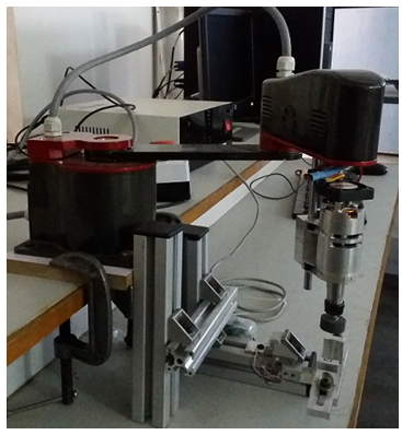 | Figure 1. Customized SCARA robot |
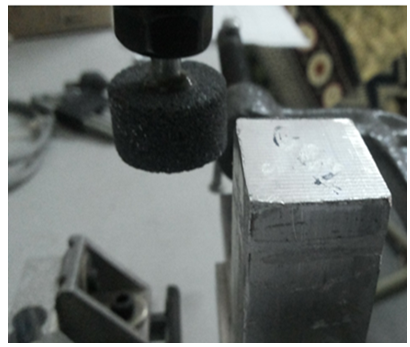 | Figure 2. Deburring of rectangular component |
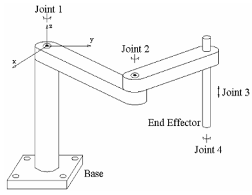 | Figure 3. Schematic representation of SCARA robot |
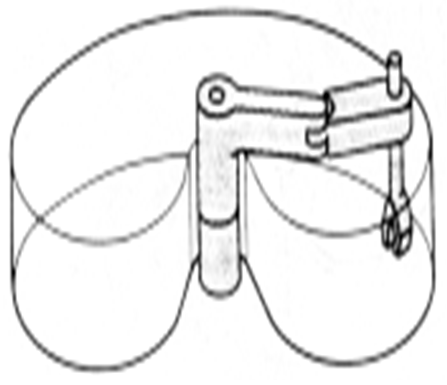 | Figure 4. Work volume of a SCARA robot |
2. Data Used
- Link lengths of the customized robot are link 1=0.200m and link 2=0.150m. The data used produces rectangular path. Figure 5 presents the schematic representation of top view of a SCARA robot used for rectangular path. Here L1 and L2 represents the link length of joint 1 and joint 2 respectively.
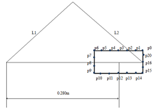 | Figure 5. Schematic representation of SCARA robot for rectangular path |
|
3. Video Graphic Analysis
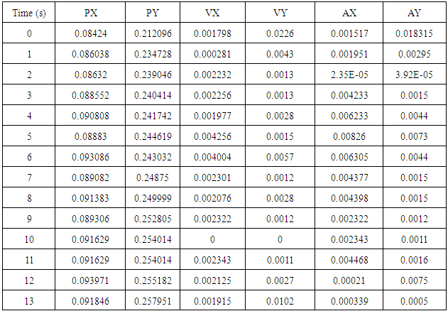
- Video graphic analysis is a technical analysis [4-6] done by the visual observation method by slow motion replay and by freezing the frame as and when required.In the present work a video is recorded when the deburring of SCARA robot is done. Then virtual protractors are placed on the two joints of SCARA manipulator. These virtual protractors move relative to the motion of the links. The recorded video is imported and analyzed in the VLC player.The purpose of the analysis is to measure the joint angles of the SCARA robot while deburring operation is done, Virtual protractors of the SCARA robot while performing the deburring operation are as shown in the figure 6. The complete deburring operation for one cycle tool is 51 seconds. Therefore, the joint angles of the links are measured with a step length of 1 second. Joint angles of link 1 and link 2 are computed using these virtual protractors and angular velocities and angular accelerations of joint 1 and joint 2 are computed using differentiation method.
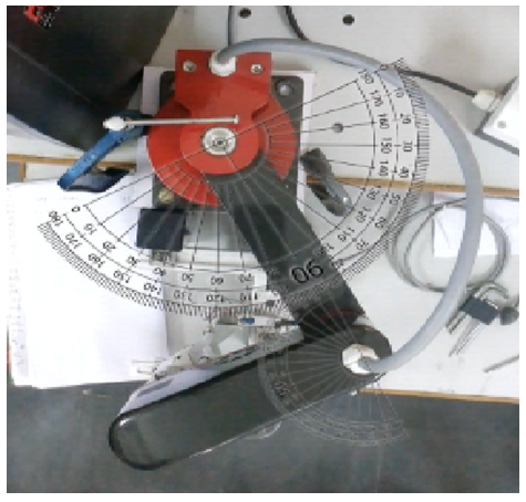 | Figure 6. Top view of SCARA robot withvirtual protractors |
4. Kinematic Analysis of a SCARA Robot
- This section presents kinematic validation of a SCARA robot done in video graphic and MATLAB analysis. Figure 7 presents angular displacement of joint 1 with respect to time, from this it is observed that there is no difference between the results obtained from the video graphic analysis and mathematical analysis done in MATLAB.
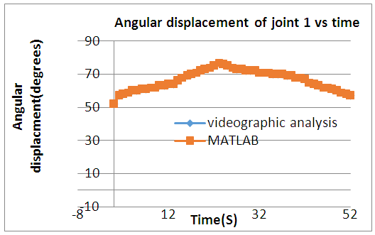 | Figure 7. Angular displacement of joint 1 vs time |
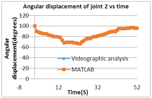 | Figure 8. Angular displacement of joint 2 vs time |
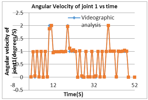 | Figure 9. Angular velocity of joint 1 vs time |
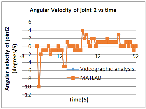 | Figure 10. Angular velocity of joint 2 vs time |
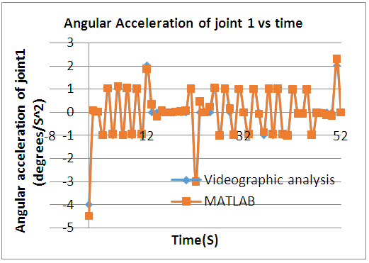 | Figure 11. Angular accelaration of joint 1 vs time |
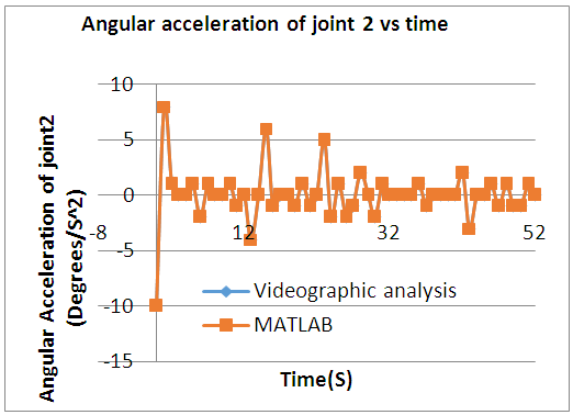 | Figure 12. Angular accelaration of joint 2 vs time |
5. Conclusions
- In the present work, for verification of the kinematics of a SCARA robot video graphic analysis and MATLAB are used. It is observed that video graphic and MATLAB analysis are yielding the same results. Further work can be extended for positional analysis of a rectangular component with in the work volume of a SCARA robot.
ACKNOWLEDGEMENTS
- We acknowledge our thanks to UGC (Minor research project) for granting us this project. We also thank our Management and TEQIP-II for sponsoring to attend this conference.