Rajesh A. R.1, Joseph Gonsalvis2, Venugopal K. A.1
1Mechanical Engineering, Malnad College of Engineering, Hassan, India
2St. Joseph Engineering College, Vamanjoor, Mangalore, India
Correspondence to: Rajesh A. R., Mechanical Engineering, Malnad College of Engineering, Hassan, India.
| Email: |  |
Copyright © 2016 Scientific & Academic Publishing. All Rights Reserved.
This work is licensed under the Creative Commons Attribution International License (CC BY).
http://creativecommons.org/licenses/by/4.0/

Abstract
Altered tooth-sum gearing is a unique type of non-standard gearing having their profiles shifted due to altering the tooth-sum for a specified center distance and module. This approach is aptly termed as Z± gearing because it involves increasing the sum of teeth (positively altered toot-sum or aptly Z+ gearing) or decreasing the sum of teeth (negatively altered tooth-sum or aptly Z− gearing) of the mating gears working on an operating pressure angle. Here, both the center distance and gear ratio remains unaltered, such a study is less explored in gear research. This paper deals with determining experimental bending stress in standard and altered tooth-sum spur gears having involute form, further the results are compared with AGMA bending stress. For this purpose a Gear Tooth Bending Test (GTBT) fixture is developed which uses a single tooth specimen having a strain gauge bonded in its fillet region. Under the application of load a strain indicator reads out the strain. The specimen is a single tooth model having accurate involute profile and circular fillet, it is developed using advanced modeling software and manufactured using CNC machine. From the experiment it is observed that the tooth of Z− gearing subjected to positive profile shift has a lower bending stress (favorable) and the tooth of Z+ gearing subjected to negative profile shift has a higher bending stress (unfavorable, of course with higher contact ratio) compared to the tooth of standard gearing. This infers that the bending strength of a gear tooth can be influenced by altered tooth-sum design. The results obtained closely agree with AGMA values.
Keywords:
Bending stress, Altered tooth-sum, Single tooth specimen, Tooth bending test fixture
Cite this paper: Rajesh A. R., Joseph Gonsalvis, Venugopal K. A., Design and Testing of Gears Operating between a Specified Center Distance Using Altered Tooth-sum Gearing (Z± Gearing), Journal of Mechanical Engineering and Automation, Vol. 6 No. 5A, 2016, pp. 102-108. doi: 10.5923/c.jmea.201601.19.
1. Introduction
A gear tooth is essentially a short cantilever beam subjected to bending stress induced in the fillet region. Due to the angularity of load applied the bending stress on tension and compression sides are different, the tension side being significant and should be as low as possible from design perspective. One common method to reduce the bending stress is to modify the involute profile by S0 or S± gearing involving profile shift. Unlike to these two, altered tooth-sum gearing (Z± gearing) involves profile shifting without change in center distance for a given module while working on an operating pressure angle  This results in total profile shift that is distributed among the mating gears. In Z± gearing the mating gears are subjected to negative teeth alteration with positive profile shift and vice versa. The amount of profile shift X1 on pinion is optimized for equal bending stress [2]. As the teeth of Z± gearing are non-standard gear teeth experimental evaluation of bending stress is felt necessary to judge its practicability. For this purpose a Gear Tooth Bending Test (GTBT) fixture is developed which makes use of a single tooth specimen and a calibrated strain gauge arrangement. When load is applied at tip of the gear tooth the strain in the fillet is indicated in the strain indicator from which the gear bending stress is estimated. In this investigation a standard gearing of tooth-sum Zs=50, GR 1:1, 4mm module, 20 mm face width, 9.81N/mm tangential tooth load, 20° pressure angle and Z± gearing with teeth alteration Ze=±2 are considered. Since GR is unity, Z1xZ2=25x25 and center distance is 100 mm. When teeth alteration of Ze=−2 (Z− gearing) is considered the mating gears will have a reduced tooth-sum of 48 (Z1’xZ2’=24x24) and a total profile shift of Xe=+1.14 is obtained which when equally distributed among the mating gears will be X1, X2=+0.570 based on equal root strength condition [2]. Similarly, when teeth alteration of Ze=+2 (Z+ gearing) is considered the mating gears will have an increased tooth-sum of 52 (Z1’xZ2’=26x26) and a total profile shift of Xe=−0.828 is obtained which when equally distributed among the mating gears will be X1, X2=−0.414 based on maximum contact ratio condition [5]. The bending stress induced in the tooth of Z− gearing is observed to be less, thus favoring gearing to have a stronger tooth.The main objectives of this study are: 1) Design and development of standard and Z± gearing teeth samples having involute form.2) Development of GTBT fixture and strain measuring arrangement. 3) Determination of AGMA bending stresses in standard and Z± gear teeth.4) Experimental determination of strain in both standard and Z± gear teeth.5) Evaluation of experimental bending stress and its comparison with AGMA bending stress. 6) Draw conclusions on bending strength of standard and Z± gearing.
2. Literature Review
From the available literature it is understood that a pair of spur gears of standard tooth-sum and module operating between standard center distance, often may not meet certain requirements like exact velocity ratio, bending strength, quietness etc. Hence gear designers have resorted to the methods like use of profile shift, use of circular or elliptical fillets, use of stress relievers etc. Some of the researchers have reported about its practicability by experimental investigations using strain gauge and photoelasticity methods. Maag [1] was the first to use the principle of generating the involute tooth using rack type cutter, he was also first to generate the involute tooth with profile shift. The amount of profile shift, its calculation and use has been discussed by Gitin Maitra [2]. Merritt [3] mentioned that S± gearing can be used to confirm different tooth-sums over a specified centre distance. M. Koilraj et al. [4] have calculated tooth-fillet bending stress for both standard and corrected gears, he has clearly enumerated the use of AGMA equation using bending geometry factor. A.R. Rajesh et al. [5] have analytically studied the influence of altering the tooth-sum on bending stress in external spur gears under static loading. It is reported that by altering the tooth-sum it is possible to benefit gearing and also reported that negatively altered tooth-sum gearing results in lower bending stress and vice versa. Sanders [6] has reported that elliptical profile can be used to create larger fillet curvatures that can yield lower bending stress than circular fillets, he also claims that each gear size will have a unique and optimum elliptical shape. Vishwas S. Jadhav and S.B Wadka [7] have developed an experimental setup to compare the induced gear tooth stresses with Lewis equation. In addition, the effect of holes in gear blank drilled for weight reduction purpose is examined. Konstandinos G. Raptis et al. [8] have used photoelasticity for the rating of gear tooth strength and compared the results with that of FEA. Dr Joseph Gonsalvis et al. [9] developed a power re-circulating gear test rig to load test a set of gears (both standard and altered tooth-sum) using back to back (FZG) principle which uses an input torque meter and a loading torque meter. The torque meter employed helps in applying metered torque which eliminates the twisting of long shaft. It needs only frictional power to drive the test rig. Sachidananda H.K et al. [10] have carried out experimental studies on altered tooth-sum gearing with respect to contact stress, power and wear losses and has justified that altered tooth-sum gearing can be used as an alternative gear system for power transmission with higher efficiency. Surajit Wadagaonkar and Sachin Shinde [11] have recommended the use of cosine gears as an alternative to standard involute gears. To simply the total degrees of freedom a single tooth model of standard involute and cosine gears were developed for same specification and performed photoelastic study to evaluate the bending and contact stresses. It is reported that due to change in tooth geometry 50% reduction in bending stress and 30% reduction in contact stress is observed.
3. AGMA Bending Stress
The bending stress equation given by Wilfred Lewis more than one hundred years ago is given by | (1) |
With the view of overcoming the assumptions underlying (1) AGMA has revised it by defining a geometry factor ‘J’. The AGMA equation for bending stress is given by  | (2) |
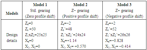
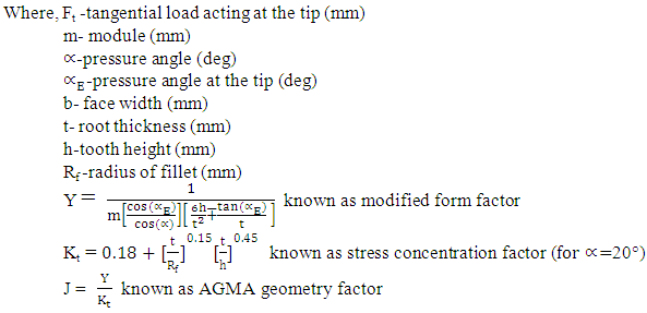 Equation (2) estimates the bending stress by introducing a bending factor ‘J’ also known as AGMA geometry factor that takes care of the stress concentration which is an important aspect in determining the bending strength of a gear tooth. Table 1 shows the design details of the experimental models for gear pair of tooth-sum 50, teeth alteration Ze=±2, pressure angle 20°, GR 1:1, 4 mm module and 20 mm face width.
 Table 1. Design details of the experimental models
 |
| |
|
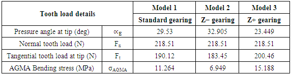
Using the tooth proportions (computed for models shown in Table 1) and equation (2) AGMA bending stress for both standard and Z± gearing are computed. The value of profile shift co-efficient allowed on pinion is selected on the basis of equal root strength condition [2].Table 2 shows the details of pressure angle and tooth loads acting at the tip for both standard and Z± gearing. Though the load acting at the tip is actually shared by two pairs of teeth, it is a common practice in gear design to consider that load is acting at the tip without sharing i.e, entire load is taken up by a single tooth. For the given specification, the bending stress induced in standard as well as Z± gearing are computed.Table 2. AGMA Bending stress in different models
 |
| |
|
4. Gear Tooth Models
The specimen used in this study is a single tooth model, the involute profile of which is geometrically computed and accurately developed using SOLID EDGE. Fig.1 shows the part models of tooth specimen used for manufacturing in CNC machine. 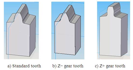 | Figure 1. CAD models of test specimen |
The test specimens are shown in fig.2 (a). Fig. 2(b) shows the strain gauge bonded on the fillet of one of the test tooth. The strain is indicated in the strain indicator under the application of load.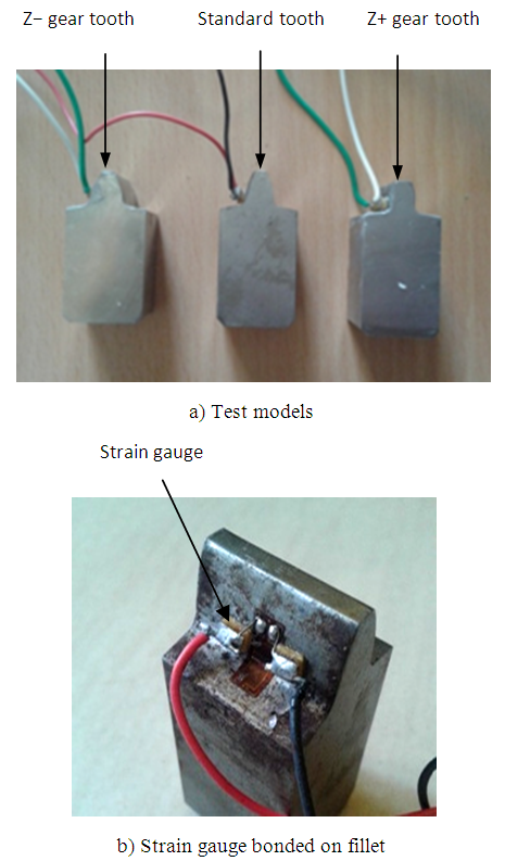 | Figure 2. Single tooth test specimen |
5. Experimentation
The experiment for determining the bending stress in the standard and Z± gear teeth are carried out with the help of GTBT fixture. It is developed to evaluate the bending stress in a most convenient way, the specimen is designed to have only one tooth facilitating proper and complete loading. The main parts of GTBT fixture include: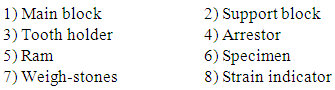 Fig. 3(a) shows the support block accommodating the specimen in a holder to the desired orientation with respect to the direction of the applied load. The holder is hardened so that it is not indented by the grub screws thereby allowing the tooth to take up the entire load. Fig. 3(b) shows the GTBT fixture assembly ready to receive the load.Fig.3(c) shows the arrestor which is firmly fixed to the main block using two long bolts; it has two fine adjustment screws that will help in locating the tip of the gear tooth specimen precisely under the plunger of the ram to receive the load. The strain gauge is connected to a strain indicator that indicates micro strain when load is applied as shown in fig. 3(d).
 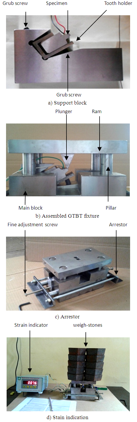 | Figure 3. Components of GTBT fixture |
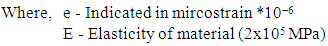
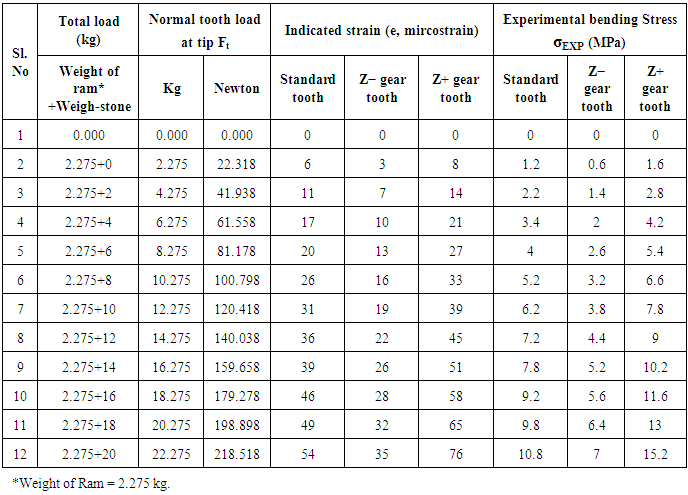
Equation (3) is used to compute the bending stress induced in the gear tooth. Since there is only one tooth the entire load acts on it and the specimen is oriented at an angle equal to the pressure angle at the tip depicting the situation similar to actual loading. The load on the gear tooth is applied by simply placing the weigh-stones on the top of the ram; the specimen will now be subjected to strain. Table 3 shows the tabulated results of strain and the evaluated bending stress induced in all the three models.  | (3) |
 The procedure consists of following simple steps:1) Place the specimen along with holder in the support block and orient the tooth to the desired loading angle by operating the grub screws.2) Place the support block in the slot provided in the main block and fix the arrestor to the main block. 3) Establish the connection between the strain gauge and strain indicator.4) Align the ram using guides and adjust the screws in the arrestor to locate the tooth tip exactly under the plunger of the ram.5) Allow free descend of the ram and note down the reading of strain indicator (mircostrain).6) Further, place the weigh-stones on the ram in steps of 2 kg and note down the corresponding readings of the strain indicator (mircostrain).7) Estimate the bending stress using (3). 8) Tabulate the results and plot the graph.
6. Results and Discussion
In this section the results obtained from the experiment are presented and analyzed to draw useful inference. Table 3 shows the strains induced in standard and Z± gearing. The plots of bending stress versus applied load for standard as well as Z± gearing are plotted in fig. (4).Table 3. Readings of mircostrain and estimated experimental bending stress
 |
| |
|
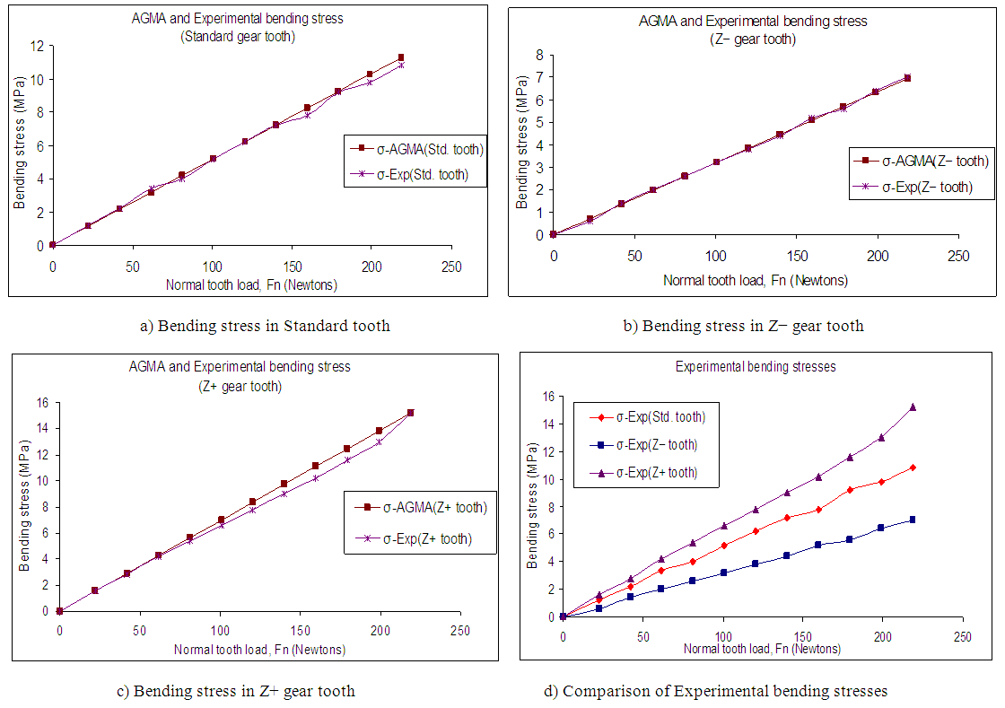 | Figure 4. Plots of Bending stress versus applied load |
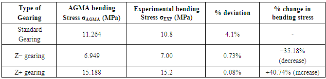
Figs 4(a) through 4(b) show the variation of bending stress in standard and Z± gear tooth against the applied load for both AGMA and experimental values. A maximum static load of 218.51(N) is applied. From plot in fig. 4(d) it can be seen that for any specific load the bending stress is lower in the tooth of Z− gearing compared to that of standard gearing. Table 4 compares the results for a maximum normal tooth load of 218.51(N), the bending stress in the tooth of Z− gearing is considerably reduced due to positive profile shift, while for Z+ gearing it is considerably increased due to negative profile shift (of course with a higher contact ratio), both having the same center distance and gear ratio as that of standard gearing. This shows that with Z± gearing the bending strength of a gear tooth can be increased when Z− gearing is adopted. As the deviation of results between AGMA and experimental methods are minimum it infers that the bending stress estimated by experimental method strongly agrees with AGMA bending stress. Table 4. Comparison of bending stresses
 |
| |
|
7. Conclusions
Though AGMA results regarding modifications in tooth profile shows significant changes in bending stress, it is always necessary to investigate and confirm it experimentally and then draw conclusions for its practicability. The prime aim of this study was to develop a GTBT fixture and single tooth specimen to conveniently evaluate the bending stress under static loading for both standard and Z± gearing for the purpose of comparison. The bending stress induced is lesser in Z− gear tooth (favorable due to positive profile shift) and greater in Z+ gear tooth (unfavorable due to negative profile shift) than that of standard gear tooth, both without changes in center distance and gear ratio. Though the bending stress in Z+ gearing is high, it can be traded off with lower noise and vibration levels as it will have a higher contact ratio due to reduced operating pressure angle [5]. In the light of the above discussion the following conclusions are drawn:1) As Z± gearing have profile correction without change in center distance, they can be categorized as unique type of profile shifted gearing.2) Altering the tooth-sum essentially modifies the tooth geometry as profile shift is introduced for a specified center distance and module.3) The change in shape of profiles of standard and altered tooth-sum gear tooth can be visibly distinguished. 4) Since tooth profile is seriously an important geometrical entity in gearing, minor changes in its shape has a significant effect on the bending strength.5) Reduction of bending stress in Z− gearing is due to positive profile shift and vice-versa. 6) As the values of experimental bending stress for both standard and Z± gearing strongly agrees with AGMA stresses the approach and experimental setup can be considered as reliable.Considering the given tooth-sum, the bending stress in Z− gearing is reduced by 35.18% (favorable), while for Z+ gearing it is increased by 40.74% (unfavorable), changes of such high magnitude is not possible with other alternatives. Thus it can be concluded that Z± gearing is a promising way of designing gears with higher bending strength which can operate on the center distance and gear ratio same as that of standard gearing.
ACKNOWLEDGMENTS
The authors thank other authors in the reference without whose valuable information it would not be possible to bring out this article.
Nomenclature
Zs, Zs’- Standard tooth-sum, Altered tooth-sum Z,, Z2-Number of teeth on standard pinion, gearZe -Number of teeth altered Z1’, Z2’-Altered number of teeth on pinion, gearXe-Total profile shiftX1, X2 - profile shift coefficient on pinion, gearFn, Ft-Normal tooth load, Tangential tooth loadσAGMA - AGMA bending stressσEXP - Experimental bending stress
Abbreviations
STS-Standard tooth-sum ATS-Altered tooth-sum (Z± gearing)GTBT-Gear Tooth Bending TestHPSTC-Highest Point of Single Tooth ContactBS-Bending stressGR-Gear ratioNCR/HCR-Normal/High Contact ratio
References
| [1] | Maag. M, “Maag Gear Book”, Maag Gear Wheel Co. Ltd., Zurich 1963. |
| [2] | Gitin Maitra, “Hand book of gear design”, TMH, New Delhi. |
| [3] | Merritt. H.E, “Gear Engineering”, 3rd Edition, Pitman, London, 1962, pp 124-125. |
| [4] | M. Koilraj, Dr. G. Muthuveerappan, Dr. J. Pattabiraman, “An improvement in gear tooth design methodology using finite element method”, IE (I) Journal - MC Vol. 88 2007, pp 8-12. |
| [5] | A.R. Rajesh, Dr. Joseph Gonsalvis and Dr. K.A. Venugopal, “A study on influence of altering the tooth-sum on bending stress in external spur gears under static loading”, International Journal of Recent Development in Engineering and Technology, Vol. 3, Issue 1, July 2014, pp 179 to 184. |
| [6] | Aaron Anthony Sanders B.S, “An experimental investigation of influence of Elliptical root shapes and asymmetric teeth on root stresses and bending fatigue lives”, MS Thesis, Ohio state university, 2010. |
| [7] | Vishwas S. Jadhav and S. B. Wadka, “Analytical and experimental evaluation of gear tooth stresses with holes in gear body”, National conference on Advances in material and Manufacturing technology, Dept. of Mechanical engineering, Punjab Engineering College, Deemed University, Chandigarh (UT), India, pp 375-379. |
| [8] | Konstandinos B. Raptis, Th. N. Costopoulus et.al. “Rating of spur gear strength using photoelasticity and the finite element method”, American journal of engineering and applied sciences 3 (1), 2010, pp 222-231. |
| [9] | Joseph Gonsalvis, Prakash, H.K. Sachidananda and A.R. Rajesh, “Design and Development of Power Re-circulating Gear Test Rig”, 13th International Conference on “Applied Mechanics and Mechanical Engineering AMME-13”, 27-29 May 2008, Military College of Engineering, Cairo, Egypt. |
| [10] | Sachidananda H.K, Joseph Gonsalvis, H.R Prakash, “Experimental investigation of fatigue behavior of spur gear in altered tooth-sum gearing”, Front. Mech. Eng., Higher education press and springer-Verlag Berlin Heidelberg 2012, pp 1-11. |
| [11] | Surajit Wadagaonkar and Sachin Shinde, “Cosine Gear Stress Analysis with Experimental Validation, and Comparison with Involute Gear”, International Journal of Innovative Science, Engineering and Technology, Vol.2, Issue3, March 2015, pp 438-443. |

 Abstract
 Reference
 Full-Text PDF
 Full-text HTML