Venugopal T. R.1, Muralidhara1, Rathnamala Rao2, Prasad Prabhu1
1Department Mechanical Engineering, NMAMIT, Nitte, India
2Department of Electronics and Communication, NITK, Suratkal, India
Correspondence to: Venugopal T. R., Department Mechanical Engineering, NMAMIT, Nitte, India.
| Email: |  |
Copyright © 2016 Scientific & Academic Publishing. All Rights Reserved.
This work is licensed under the Creative Commons Attribution International License (CC BY).
http://creativecommons.org/licenses/by/4.0/

Abstract
Size of the tool electrode used in micro-EDM is of the order of few tens to few hundred micrometers and the energy supplied is also small. This feature of micro-EDM demands in-situ fabrication of tool electrodes. This paper proposes the development of a simple self-adaptive positioning and feeding system for in-situ tool grinding based on block electrical discharge grinding principle. During tool grinding sacrificial block is continuously fed towards the rotating tool electrode while maintaining the spark gap. This is achieved by integrating an in-house fabricated flexurally amplified piezoactuator for feed control in the grinding attachment of the micro-EDM system. Feed control experiments performed on the developed system shows good agreement of output feed displacements produced with reference input displacements. Therefore, the developed feed control system can be used for in-situ tool grinding in micro-EDM.
Keywords:
Micro-EDM, In-situ tool grinding, Piezoactuator, Tool feed control
Cite this paper: Venugopal T. R., Muralidhara, Rathnamala Rao, Prasad Prabhu, Piezoactuator Based Feed Control System for In-Situ Tool Grinding in Micro-EDM, Journal of Mechanical Engineering and Automation, Vol. 6 No. 5A, 2016, pp. 86-92. doi: 10.5923/c.jmea.201601.16.
1. Introduction
In electrical discharge machining (EDM), material is removed by melting and evaporation by rapid and repetitive pulsed application of electrical energy. Being a non contact process, tool force involved is negligible [1, 2]. Process can be applied to all electrically conducting materials regardless of their other properties. Owing to these advantages, EDM principle is best used for the fabrication of micro structures which finds application in Micro Electro Mechanical System (MEMS) devices and various other fields [3, 4, 5].In micro-EDM, size of the tool electrode used is of the order of few tens to few hundred micrometers and the energy supplied is also of the order of few hundred micro joules [6, 7]. This feature of micro-EDM makes fabrication and handling of tool electrodes a difficult task. In order to achieve the required positioning accuracy and repeatability, tool electrode must be fabricated on the micro-EDM setup itself. Thus in-situ tool fabrication is an essential part of micro-EDM. Commercial micro-EDM systems are equipped with tool grinding facility which employs wire electrical discharge grinding (WEDG) or block electrical discharge grinding (BEDG). In WEDG a guided running wire is used as the grinding tool. In BEDG the tool electrode mounted on the rotating spindle is fed against a stationary sacrificial block. Rotating sacrificial disc is also used for tool grinding [1, 8]. During tool grinding the spark gap between the tool electrode and the sacrificial block is few micrometers only. Spark gap is a critical parameter of the process. Therefore, the mechanism used for feeding the tool must be capable of maintaining the spark gap. Conventionally all methods employ servo drives for feeding the tool. This research paper describes the development of an in-situ tool grinding attachment working on the principle of BEDG. In this system a flexurally amplified Piezoactuator is used for feed control [9]. Micro-EDM setup with in-situ tool grinding attachment is described in section 2. Feed control experiments are explained in section 3. Results and discussion in section 4, followed by conclusion in section 5.
2. Development of In-Situ Tool Grinding System for Micro-EDM
An in-situ tool grinding attachment is developed and integrated with an indigenously built prototype micro-EDM setup [10]. The developed grinding attachment works on block EDG principle. A sacrificial block is used as the grinding tool which is fed against the rotating tool electrode during grinding. The setup consists of following functional elements.
2.1. Power Supply and Pulse Control Unit
This unit consists of the circuitry for generating and switching the pulsed discharges between the sacrificial block and the tool electrode for electrical discharge grinding of the tool. Pulse energy, pulse frequency, pulse ontime etc are the major parameters in micro-EDM [6]. RC type [11] or transistor type pulse generators are popularly used for the purpose [12]. Real time sensing of the gap condition and regulation of the pulse interval is essential for stable machining process [13]. In the developed micro-EDM setup FET based pulse generator is used [9, 10].
2.2. Dielectric Filtering and Recirculation Unit
Dielectric used in the micro-EDM system is kerosene. Dielectric is recirculated by variable speed pump through an inline filtering unit. Recirculation system keeps the machining gap continuously flushed.
2.3. Tool Feed Control Unit
Function of this unit is to feed the grinding tool (sacrificial block) towards the tool electrode and also to maintain the optimum machining gap between the block and the tool electrode. During electrical discharge grinding, the voltage across the spark gap is sensed and compared with reference voltage corresponding to the desired machining gap. This feedback is used to generate the feed control signal which drives the actuator.
2.4. Actuator Used for Tool Feed Control
A quadratic arm Flexurally Amplified Piezoactuator (FAP) designed and fabricated in the lab is used for feed control. FAP consists of six piezo-electric stack actuators assembled with a quadratic arm flexural amplifier as shown in Figure 1. Length of longitudinal axis of the FAP is145mm, transverse axis is 35mm and width of FAP is 10mm.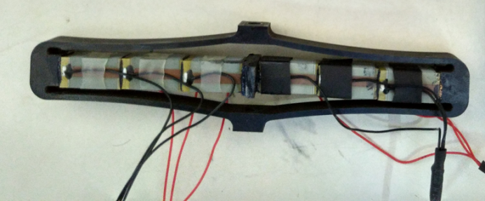 | Figure 1. Photograph of assembled quadratic arm FAP |
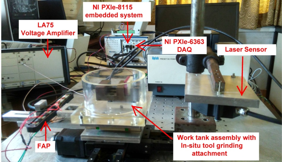
Figure 2 shows block diagram of the experimental setup for measuring the displacement of the FAP. NI PXIe1071 with NI PXIe8115 embedded controller and NI PXIe6363 DAQ (2MS/s sampling frequency) consisting of 32 analog input channels and 4 analog output channels with 16bit resolusion and 48 digital input-output lines is used in the measurement. NI PXIe8115 controller generates a sine voltage signal with 7.5V amplitude at 1Hz frequency. This signal is supplied to a linear voltage amplifier (LA75, amplification factor 20) through the analog output channel of NI PXIe6363DAQ. Amplified voltage signal (150V) is supplied to the FAP which produces the feed displacement. Displacement of the FAP is sensed by a laser displacement sensor ILD2220-20 (measuring range 20mm, 0.3µm Resolution, linearity 6µm). Analog output of the sensor is acquired by NI PXIe6363DAQ. Figure 3 shows photograph of the setup for displacement measurement.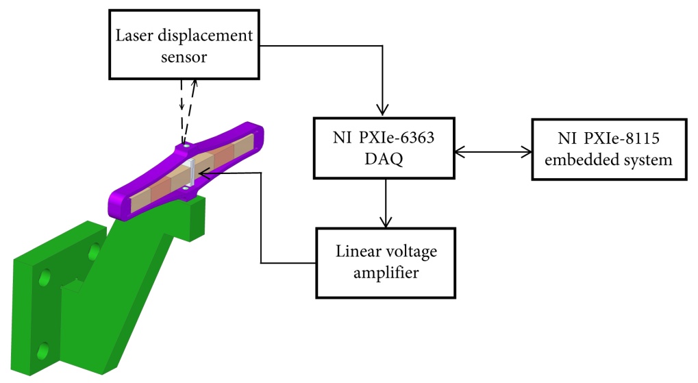 | Figure 2. Block diagram of experimental setup for displacement measurement of FAP |
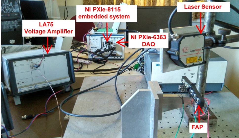 | Figure 3. Photograph of experimental setup for displacement measurement of FAP |
FAP produced a maximum displacement of 780µm against 150V input at 1Hz and indicated 50 µm hysteresis as shown in Figure 4.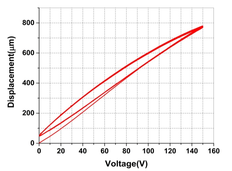 | Figure 4. Hysteresis curve between applied input voltage and output displacement for FAP |
2.5. Integration of FAP with In-situ Tool Grinding Attachment
Figure 5 shows the integration of FAP with in-situ tool grinding attachment. The worktank holding the sacrificial block is mounted on a slide plate which inturn mounted on a set of linear motion slideways. Slideways are fixed on a base plate mounted on steper motor driven X-Y stage. Blocked side of the FAP is conneted to the L-clamp fixed on the base plate. Free side of the FAP is connected to the slide plate carrying the work tank.Thus displacement of the FAP causes the slide plate and hence the worktank to move giving feed motion to the sacrificial block.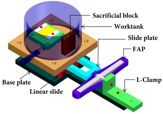 | Figure 5. FAP integrated with In-situ tool grinding attachment |
The in-situ tool grinding attachment is tested for displacement. Figure 6 sows the displacement plot against applied voltage showing hysteresis. A maximum of 680 µm displacement is produced at 150V input voltage and showed about 60 µm hysteresis.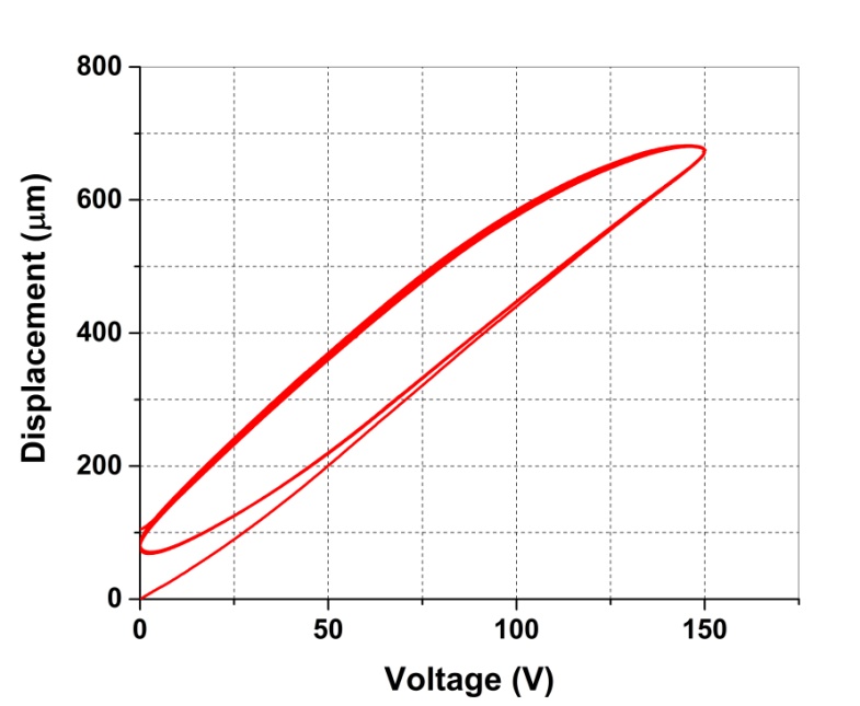 | Figure 6. Hysteresis curve for feed displacement of the In-situ tool grinding attachment with FAP |
Figure 7 shows the block diagram of the in-situ tool grinding attachment integrated with micro-EDM setup. A larger diameter electrode mounted on the spindle can be reduced in diameter down to the required micro size by in-situ tool grinding. Thus tool is prepared on the spindle so that run out and positioning error in holding the tool for subsequent micro machining can be reduced. Tool electrode is held in the tool spindle with collet (12-48V, 200W) as shown in Figure 7, which in turn mounted on the vertical attachment. This assembly is mounted on the vertical post with lead screw for vertical positioning of the tool. Work tank acts as reservoir for dielectric and hold the work piece and sacrificial block in site. Tank is placed on the linear motion slides through base plate. Tank system is connected to piezoactuator. During tool grinding feed movement of sacrificial block is controlled by FAP. The linear motion slides are mounted on XY stage through baseplate. Transverse movement of tank assembly is provided by stepper motor driven XY stage (8MT-175-50).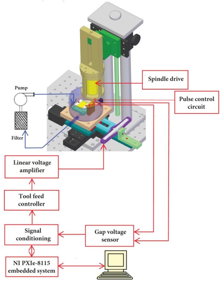 | Figure 7. Block diagram of in-situ tool grinding system with FAP for tool feed control integrated with micro-EDM setup |
3. Feed Control Experiments
Since the in-situ tool grinding attachment with FAP shows hysteresis, inverse Maxwell hysteresis model of FAP in LabVIEW software is used for feed control. Figure 8 shows block diagram of the setup for tool feed control experiments. NIPXIe8115 embedded system with and NI PXIe6363DAQ is used in the setup. Desired feed displacement of the sacrificial block is the input to the model. Model generates corresponding drive voltage as output. This voltage is supplied to the linear voltage amplifier (LA75, amplification factor 20) through the analog output channel of the NI PXIe6363DAQ. Amplified voltage is supplied to the FAP which produces the feed displacement. Feed displacement of the in-situ girding attachment is sensed by the laser displacement sensor ILD2220-20. Analog output of the sensor is acquired by NI PXIe6363DAQ. Figure 9 shows photograph of the setup for feed control experiments.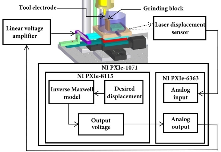 | Figure 8. Block diagram of In-situ tool grinding attachment with FAP for tool feed control experiment |
 | Figure 9. Photograph of In-situ tool grinding attachment with FAP for tool feed control |
4. Results and Discussion
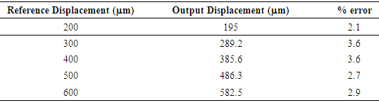
Feed control experiments were conducted on the developed setup by applying reference input displacements of 200 µm, 300µm, 400µm, 500µm and 600µm sine signal at 1Hz frequency and the corresponding output displacements were measured. Figure 10 to Figure 12 shows the experimental tool feed displacement observed for 200 µm, 400µm and 600µm reference input displacements respectively. Experimental output displacement obtained for sine signal is tabulated in Table 1. Output displacements obtained is in good agreement with reference input displacements with maximum error less than 4 percentage. 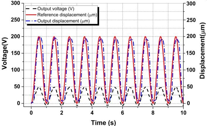 | Figure 10. Experimental tool feed displacement obtained for reference input feed displacement of 200µm |
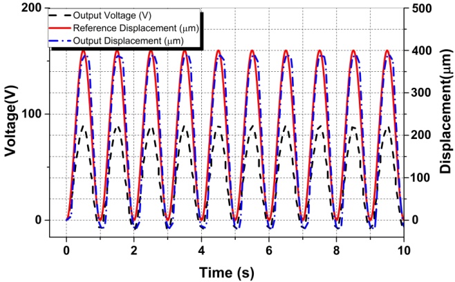 | Figure 11. Experimental tool feed displacement obtained for reference input feed displacement of 400µm |
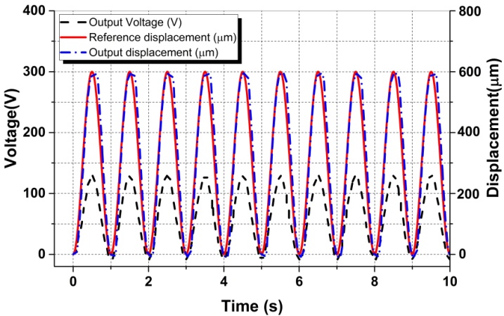 | Figure 12. Experimental tool feed displacement obtained for reference input feed displacement of 400µm |
Table 1. Experimental feed displacement obtained for sine reference input
 |
| |
|
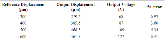
Figure 13 to Figure 15 shows experimental results obtained by giving reference input displacements as ramp signal. Output feed displacement and the corresponding drive voltage obtained for 300µm, 400µm, 500µm and 600µm ramp input is tabulated in Table 2.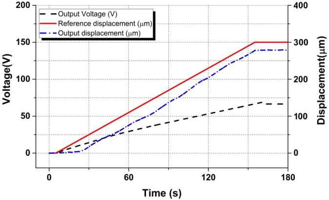 | Figure 13. Experimental tool feed displacement obtained for reference input feed displacement of 300µm ramp signal |
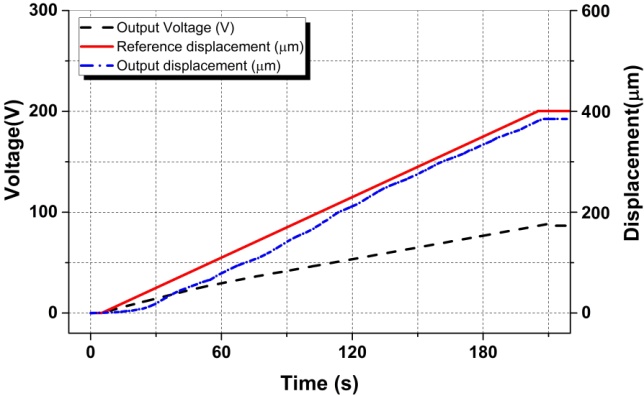 | Figure 14. Experimental tool feed displacement obtained for reference input feed displacement of 400µm ramp signal |
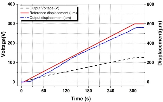 | Figure 15. Experimental tool feed displacement obtained for reference input feed displacement of 600µm ramp signal |
Table 2. Experimental feed displacement obtained for reference input displacement as ramp signal
 |
| |
|
5. Conclusions
In-situ tool grinding system is developed with in-house fabricated flexurally amplified Piezoactuator (FAP) for feed control. Developed system is integrated with indigenously built micro-EDM setup. The tool feed control system is capable of feeding the tool to a maximum of 680µm. Feed control experiments with sine signal reference input showed feed displacement with less than 4 percentage error. Output displacement obtained with ramp input showed a maximum of 6.93 percentage error. This error may be reduced by optimising the model parameters used in the feed drive. The developed FAP based feed control system can be used for further experimental investigations in in-situ tool grinding on the micro-EDM setup. Further the feed control may be extended to predict the feed movement required to reach the desired tool electrode diameter.
ACKNOWLEDGEMENTS
Authors would like to acknowledge the financial support provided by Visvesvaraya Technological University in carrying out this research work under VTU research grant scheme Research Grant No. VTU/Aca. /2010-2011/A-9/11545 dated: 10-12-2010.
References
| [1] | D.T. Pham, S.S. Dimov, S. Bigot, A. Ivanov, K. Popov, 2004, Micro-EDM-recent developments and research issues, Journal of Materials Processing Technology, 149 50–57. |
| [2] | Z. Katz · C.J. Tibbles, 2005, Analysis of micro-scale EDM process, Int J Adv Manufacturing Technology, 25: 923–928. |
| [3] | Beltrami I., Joseph C., Clavel R., Bacher J. P., Bottinellei S., “Micro and nano electric discharge machining”, Journal of materials processing Technology, 1491/1-3:p. 263-265, 2004. |
| [4] | H. Zarepur, A. Fadaei Tehrani, D. Karimi, S. Amini,2007, Statistical Analysis on electrode wear in EDM of tool steel DIN 1.2714 used in forged dies,” Journal of Material Processing Technology, 187-18 8, pp. 711-714. |
| [5] | Dario, P.; Carroua, M.C.; Croce, N.; Montesi, M.C.; Cocco, M., 1995 “Non-traditional technologies for microfabrication”. Journal of Micromechanics and Microengineering, 5: 64–71. |
| [6] | Eckart Uhlmann, Sascha Piltz, Ulrich Doll, 2005, Machining of micro/miniature dies and moulds by electrical discharge machining-Recent development, Journal of Materials Processing Technology, 167, 488–493. |
| [7] | S. Mahendran and D. Ramasamy, 2010, Micro-EDM: Overview and Recent Developments, National Conference in Mechanical Engineering Research and Postgraduate Students (1st NCMER 2010) 26-27, pp. 480-494, May 2010. |
| [8] | G. Karthikeyan J. Ramkumar. Dhamodaran, 2014, “block EDG: Issues and Applicability in Multiple Pass μED-Milling” Machining Science and Technology, 18:120–136. |
| [9] | Muralidhara, Nilesh J. Vasa, Singaperumal Makaram, 2009, “Investigations on a directly coupled piezoactuated tool feed system for micro-electro-discharge machine” International Journal of Machine Tools and Manufacture, 49, 1197-1203. |
| [10] | Venugopal. T.R., Muralidhara., Rathnamala Rao., 2014, Development of micro-EDM Incorporating In-Situ Measurement System, Procedia Material Science 5, 1897-1905. |
| [11] | Jahan M.P.; Y.S. Wong and Rahman, 2009, ‘A study on the quality micro-hole machining of tungsten carbide by micro-EDM process using Transistor and RC type Pulse generator” Journal of material Processing Technology, pp1706-1716. |
| [12] | Han F., L. D. Chen., Yu and X.Zhou, 2007, Basic study on pulse generator for micro-EDM, International Journal of Advanced Manufacturing Technology, 33, pp474-479. |
| [13] | Mu-Tian Y., and H. Chien, 2007, Monitoring and control of the micro wire-EDM process, International Journal of Machine Tools and Manufacture,47, pp148-157. |

 Abstract
 Reference
 Full-Text PDF
 Full-text HTML