-
Paper Information
- Next Paper
- Previous Paper
- Paper Submission
-
Journal Information
- About This Journal
- Editorial Board
- Current Issue
- Archive
- Author Guidelines
- Contact Us
Journal of Mechanical Engineering and Automation
p-ISSN: 2163-2405 e-ISSN: 2163-2413
2016; 6(5A): 75-80
doi:10.5923/c.jmea.201601.14

Vibration Analysis of Magnetorheological Elastomer Sandwich Beam under Different Magnetic Fields
 Abstract
 Reference
 Full-Text PDF
 Full-text HTML
Spoorthi Megha1, Susheel Kumar N.2, Rolvin D’Silva1
1Department of Mechanical Engineering, St Joseph Engineering College, Mangaluru, India
2Department of Mechanical Engineering, National Institute of Technology, Surathkal, India
Correspondence to: Rolvin D’Silva, Department of Mechanical Engineering, St Joseph Engineering College, Mangaluru, India.
| Email: |  |
Copyright © 2016 Scientific & Academic Publishing. All Rights Reserved.
This work is licensed under the Creative Commons Attribution International License (CC BY).
http://creativecommons.org/licenses/by/4.0/

Vibration analysis is important when the applied load is not constant and induces unstable modes of vibration or resonance. This reduces performance and may cause catastrophic failure. It is important to control vibrations and limit its transfer to the secondary bodies attached to it. In the present work, a Magneto Rheological Elastomer (MRE) sandwich beam is fabricated using a MRE between two thin aluminium layers. An electromagnet setup is designed and fabricated to provide the required magnetic field. The design of electromagnet is analysed numerically using the Finite Element Method Magnetics (FEMM) software. An experimental test rig is set up to investigate free and forced vibration response of the MRE sandwich beam under zero magnetic field and magnetic fields of 50 mT, 100 mT, 150 mT, 200 mT, 250 mT and 285 mT. Results reveal a frequency left shift trend. It has been observed that the first natural frequency of the MRE sandwich beam decreases by 11.96% when the applied magnetic field is increased from 0 mT to 285 mT at the location 120 mm from the fixed end of the MRE sandwich beam.
Keywords: Magnetorheological elastomer, Sandwich beam, Electromagnet, Free vibration test
Cite this paper: Spoorthi Megha, Susheel Kumar N., Rolvin D’Silva, Vibration Analysis of Magnetorheological Elastomer Sandwich Beam under Different Magnetic Fields, Journal of Mechanical Engineering and Automation, Vol. 6 No. 5A, 2016, pp. 75-80. doi: 10.5923/c.jmea.201601.14.
Article Outline
1. Introduction
- Vibrations are present in all machines and structures and are mostly undesirable. Unwanted vibrations could lead to system failure. The mitigation or control of vibrations is of prime importance in any design. In the past decade, many vibration control methods have been proposed: passive, semi-active and active vibration control, for a wide range of applications.A passive vibration system consists of a mass, a spring and a damper. However, passive systems are only effective over a very narrow frequency range. As the excitation frequency changes, the vibration reduction effect decreases or even collapses because of mistune. In active vibration system, the disadvantages are: high consumption of energy and requirement of large activation force. The semi-active vibration system changes its material properties and can be used in real time applications without any activation force. In this system, varieties of approaches have been used to vary the natural frequency of the system by changing the structural parameter. In case of Magneto Rheological Elastomer (MRE), stiffness is varied.Magnetorheological (MR) materials exhibit rapid variations in their rheological properties such as viscosity and shear modulus when subjected to different magnetic field intensities. Since their discovery by Rabinow in 1948, it was not until 1985 that the pioneering work on the magnetically sensitive elastomer was firstly reported by Rigbi and Jilken. MR materials have developed into a family comprising of MR fluids, MR foams and MR elastomers [1].MREs are a class of smart materials. MREs are mainly made up of matrix, magnetisable particle as reinforcement and additives. Natural rubber or silicon rubber is used as base material. Spherical iron particles are generally used as filler materials to fabricate MREs. Iron has one of the highest saturation magnetisation value of metallic elements with Ms=2.1 Tesla. It also has high permeability, low remnant magnetisation and high saturation magnetisation. This provides high MR effect. Additives are used to decrease the basis modulus of MRE materials and conglutination of the molecules [2]. In MRE vibration isolator, the natural frequency is varied by changing the stiffness of MRE by application of the magnetic field. This field is applied using electromagnets which can be easily varied according to the requirement. The analysis of electromagnet design is done with the help of FEMM and it is found that 0.28 T is required at the air gap [3]. The effectiveness of the MRE depends upon several factors like its composition, iron particle size etc. which has to be taken care to get better results.MRE is usually used as a stiffness-changeable spring in the semi-active vibration absorber. In order to get perfect vibration control, low dynamic damping of MRE is need. The main source of dynamic damping is the friction between iron particles and rubber matrix. And the friction is mainly influenced by the strain amplitude and test magnetic field [4].The experimental results show that the first natural frequency of the MRE sandwich beam decreased as the magnetic field applied to the beam was moved from the clamped end of the beam to the free end of the beam. The MRE sandwich beam had the capability to left shift the first natural frequency when the magnetic field was increased in the activated regions [5].
2. Fabrication of Magnetic Field Generator
- MRE exhibits MR effect under the application of magnetic field. Hence design of magnetic field generator is very important. For fabrication of DC electromagnet setup, the material suitable for core and coil material is identified. The soft carbon steel SAE1018 is good core material and copper (AWG14) being good conductor is selected as coil material.The core geometry is selected such that a continuous path is provided for the flow of magnetic flux and to generate minimum leakage flux is [6]. It is made up of square rod of cross sectional area 25mm*25mm.The MFG is designed to produce 0.6 mT at the centre of the core and 0.3 mT in the air gap.
2.1. Analysis of Electromagnet Using FEMM
- The electromagnet was designed and analysed numerically using the Finite Element Method Magnetics (FEMM) software. This software allows the user to input the geometry of the particular electromagnet, as well as, the number of electromagnetic coils to be used in the magnet design.FEMM confirms the design. The magnetic field strength in the center of the coil is found to be around 0.6 T and the magnetic field strength decreases at the air gap and it is found to be around 0.3 T as shown in Fig. 1. The electromagnet is designed for a maximum current of 3A. The design shows minimum leakage of magnetic flux, and hence is considered optimum.
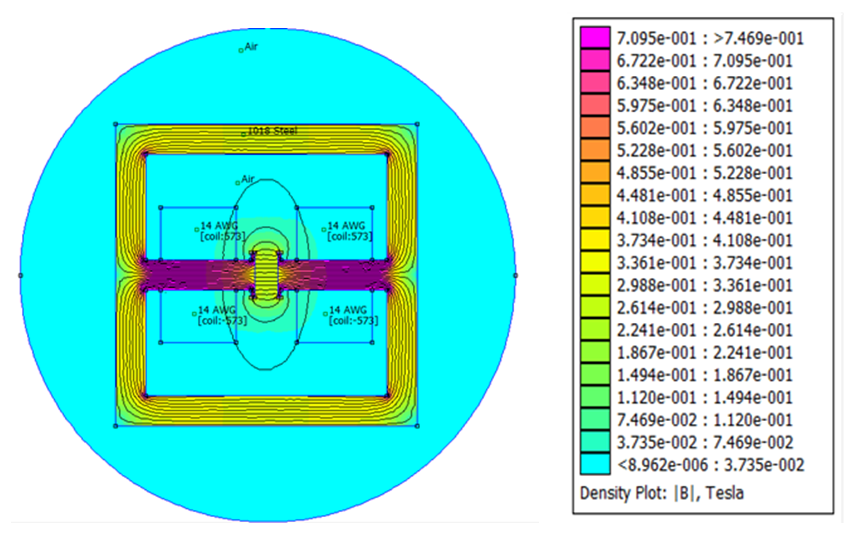 | Figure 1. FEMM solution- flux density plot of electromagnet test setup |
3. Fabrication of MRE Sandwich Beam
- A MRE is a composite material whose mechanical properties are changed when an external magnetic field is applied. It is made of two main components: matrix and dispersed particles. The silicone rubber contributes elastic properties to the cured sample and the iron particles allow the samples to be influenced by application of a magnetic field. The materials used for the MREs in this investigation are:Ÿ Silicon Rubber (XIAMETER® RTV-3483 Base) Ÿ Curing agent (XIAMETER® RTV- 3083)Ÿ Iron particles (type C3518)Ÿ Binders.
3.1. Fabrication of MRE Material
- From the literature it is found that the MRE of 27% by volume of iron and 73% by volume of silicon rubber is found to be optimum [2]. The mass of the silicon rubber and iron particles is calculated based on the percentage volume required. The density of silicone rubber and iron particles are 1.15 g/cm3 and 7.86 g/cm3 respectively.Fig. 2 shows schematic of fabrication of both isotropic and anisotropic MR elastomers.
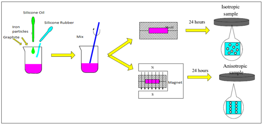 | Figure 2. Schematic of fabrication of both isotropic and anisotropic MR elastomers |
3.2. Fabrication of a Sandwich Beam with MRE Core
- The Magneto rheological sandwich beam is made up of three layers: the top and bottom layers are aluminium and the core is of MRE material. Thin aluminium plates were chosen for elastic surface plates due to its low damping properties and relatively high stiffness properties compared to those of MREs. Additionally, aluminium’s relatively magnetic permeability is equal to zero, which indicates that it does not affect the distribution and strength of the magnetic field.The beam has length L =252 mm and width b = 19 mm, the thickness of the upper aluminium layer and the bottom aluminium layer is h1 =1.5 mm, and the MRE layer thickness is h2 = 3 mm as shown in Fig. 3.
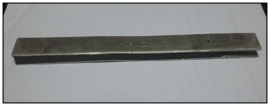 | Figure 3. Photograph of MRE sandwich beam |
4. Experimentation
- The MRE sandwich beam is placed in the form of cantilever as shown in Fig. 4 and Fig. 5. One end of the beam is fixed firmly on the holder and another end is free. An accelerometer (produced by KISTLER, type: IEPE) is fixed at the tip of free end of the beam. Electromagnet setup is placed in such a way that the field passes through the beam at a distance of 120mm from the fixed end. The magnetic lines of force are perpendicular to the flat surface of the beam. Once all the devices are connected and the circuit is built, the beam is given initial excitation using impact hammer (produced by “PCB piezotronics”, model: 086303) for obtaining the behavior of the beam under free vibration. The output from accelerometer is sent to a DAQ (by National Instruments: sine IEPE- NI9234 and NI9162). The DAQ is connected to the computer which has ‘LabView’ software to process the signal and give out the result in the form of graph or data. Procedure is repeated for several trials to obtain better results.
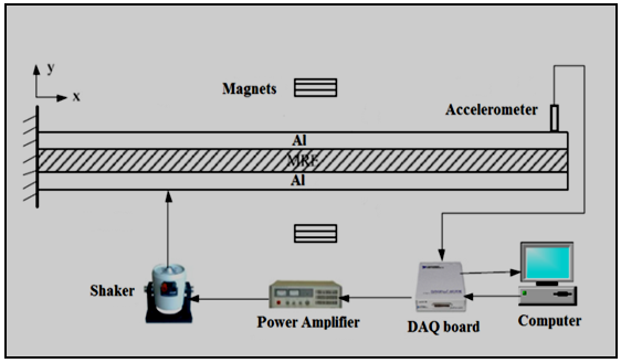 | Figure 4. Experimental setup for vibration analysis of the MRE sandwich beam: schematic |
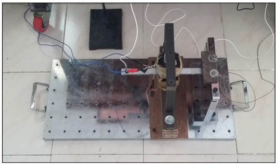 | Figure 5. Experimental setup for vibration analysis of the MRE sandwich beam |
5. Results and Discussions
- The electromagnet designed for field strength of 0. 6mT at the center of core gives magnetic field strength of 0.3 mT at the air gap. It is again measured using gaussmeter and plotted against current.The magnetic field strength is almost linear as shown in Fig. 6, i.e. the magnetic field strength (B) increases linearly with increasing current (I). Therefore, magnetic field (B) is directly proportional to the current (I). The readings obtained in free vibration test are plotted as shown in the Fig. 7.
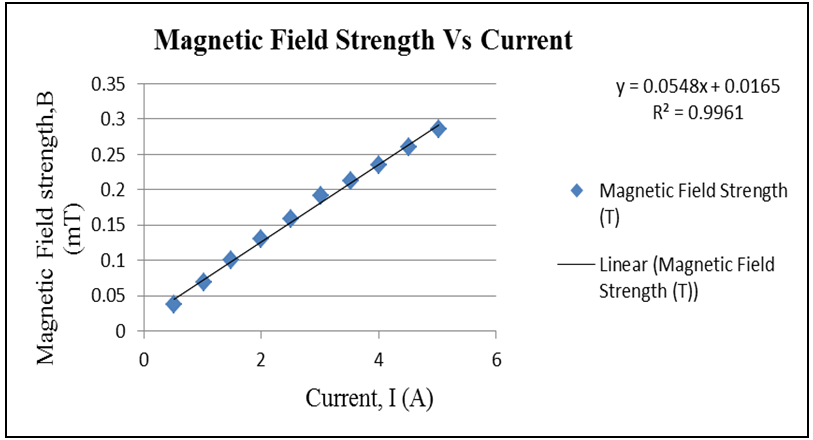 | Figure 6. Plot of Magnetic field strength (B) against Current (I) |
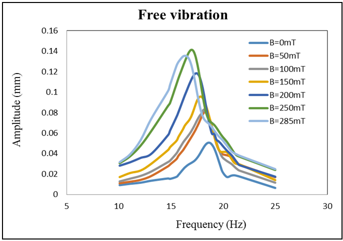 | Figure 7. Free vibration response of the MRE sandwich beam under different magnetic field intensities |
 | (1) |
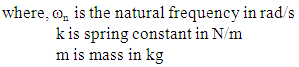 We know that the natural frequency changes as the stiffness of the material changes since the mass remains fixed. MREs are viscoelastic materials. The constitutive equation for this kind of material is significantly nonlinear and it is often described in terms of the principal extension ratios through the Ogden strain potential. This means that the shear modulus of a MRE is dominated by the stress condition, or strain energy. The complex shear modulus G∗ is assumed as the sum of the shear modulus G0 with no field applied and the shear modulus ∆G(B) induced by interparticle magnetic forces and the Young’s modulus induced by interparticle magnetic forces can be given as ∆E(B) [5].The complex shear modulus G∗ and the equivalent Young’s modulus E∗ can be expressed as
 | (2) |
 | (3) |
6. Conclusions
- The conclusion of this work can be presented in two parts: first part involves the fabrication of electromagnet test rig and the second for the vibration analysis of MRE. The electromagnet for field strength of 0.6 Tesla is successfully designed for the test rig. This electromagnet test rig is then optimised by solving 2D problem using Finite Element Method Magnetics (FEMM) software. The design is found to be optimum and generates 0.3 Tesla of magnetic field in the air gap. The test rig is fabricated and the field strength is measured again using gauss meter for its correctness.In the second part of this work, an attempt is made to show the MR effect of MRE sandwich beam and the change in natural frequency of the system. This study reveals the possibility of shifting the natural frequency to a lower frequency by applying a small nonhomogeneous magnetic field. This is achieved by partially activating a region of the sandwich beam. This study shows the trend of a frequency left shift. It has been observed that the first natural frequency of the MRE sandwich beam decreases by 11.96% when the applied magnetic field is increased from 0mT to 285mT at the location 120 mm from the fixed end of the MRE sandwich beam.
ACKNOWLEDGEMENTS
- The Authors are grateful to the In-charge and Staff of Centre for System Design Labs, NITK - Surathkal for providing the lab facilities for the experimentation purpose.