-
Paper Information
- Next Paper
- Previous Paper
- Paper Submission
-
Journal Information
- About This Journal
- Editorial Board
- Current Issue
- Archive
- Author Guidelines
- Contact Us
Journal of Mechanical Engineering and Automation
p-ISSN: 2163-2405 e-ISSN: 2163-2413
2016; 6(5A): 63-70
doi:10.5923/c.jmea.201601.12

Comparative Analysis of Helical Steel Springs with Composite Springs Using Finite Element Method
 Abstract
 Reference
 Full-Text PDF
 Full-text HTML
Anil Antony Sequeira, Ram Kishan Singh, Ganesh K. Shetti
School of Engineering & IT, Manipal University Dubai Campus, Dubai, U.A.E.
Correspondence to: Anil Antony Sequeira, School of Engineering & IT, Manipal University Dubai Campus, Dubai, U.A.E..
| Email: |  |
Copyright © 2016 Scientific & Academic Publishing. All Rights Reserved.
This work is licensed under the Creative Commons Attribution International License (CC BY).
http://creativecommons.org/licenses/by/4.0/

In automobile sector due to the demanding need of rapid innovation and tough competition, the old products are reengineered by new product with composite materials. Regularly new innovations are carried out in suspension area of vehicles. Fiber Reinforced Material [FRP] components are the main interest of automobile industry for replacing the steel components due to “high strength to low weight” ratio. To reduce the weight and fuel consumption to some extent, automobile industries are using the Glass Fiber Reinforced Plastic [GFRP] open coil springs in suspension system of vehicle at the place of steel open coil springs. In this research, the properties of composite and steel helical spring are compared and the deciding factor is the stiffness to weight ratio. Spring geometry is modeled in CREO Software on other hand Finite Element method is used to analyze under different loading condition. Finally steel spring has been replaced by two different composite helical spring including Carbon and Kevlar.
Keywords: Helical spring, Composite spring, ANSYS work bench, Carbon and Kevlar
Cite this paper: Anil Antony Sequeira, Ram Kishan Singh, Ganesh K. Shetti, Comparative Analysis of Helical Steel Springs with Composite Springs Using Finite Element Method, Journal of Mechanical Engineering and Automation, Vol. 6 No. 5A, 2016, pp. 63-70. doi: 10.5923/c.jmea.201601.12.
Article Outline
1. Introduction
- The suspension system in wheeled vehicles used the simple form of spring called helical spring. Vehicle motion, driving and power transfer is the basic role spring in suspension system. For the economy, comfort riding, quality and comfort of user, automobile industry tends to replace steel helical spring with composite helical spring. Due to high strength to weight ratio, there is increased interested in the replacement of steel helical spring with composite helical spring. In steel helical spring have limitation on applied load. Geometrical alignment of car and erodes of other parts of car create problem due to applied more load than capacity. Consider durability and strength are very important point during design of the spring. For improvement of car dynamic spring weight reduction is also important parameter. [1]In this research, behavior of Carbon and Kevlar composite helical spring and steel helical spring with related to light vehicle suspension system investigated by a static analysis. In ANSYS software composite spring used at place of steel helical spring and the results are compared with analytical solution. Aim of this research to compare the mechanical properties of composite helical spring with steel helical spring in area like load carrying capacity, stiffness and weight saving of composite spring. Epoxy has better mechanical property compared to any polyester because it is relatively sensitive to moisture. New age composite fibers made out of carbon, glass and reinforced Kevlar resins are found to be exhibiting specific high strength and modules [2].
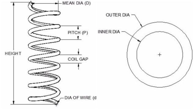 | Figure 1. Terminology of Helical coil spring |
1.1. Structural Steel Spring
- Depending upon the applications the classification of materials are done for various types of metallic springs. Initially there is no application of load but later on the load is applied in an ascending order. The spring which we are using for the analysis is compression helical spring in other words known as open coil spring. These springs are used in shock absorbers of suspension systems in automotive vehicles and some other applications such as drum brake springs for maintaining the force between contacting surfaces. The strain energy of the material of the spring is an important factor to be considered.

1.2. Kevlar Fabric Spring
- Kevlar is a para-aramid fiber which displays excellent dimensional stability over a wide range of temperatures for prolonged periods. Even at temperature of 320F. Kevlar shows essentially no strength loss Kevlar fiber does not melt or support combustion but will start to decompose at about 800F. Currently, Kevlar has many applications, ranging from bicycle tyres and racing sails to body armour because of its high tensile strength to weight ratio by this measure it is five times stronger than steel on an equal weight basis. [3]
1.3. Carbon Fibre Fabric Spring
- To form a composite carbon fibers are mixed with other materials. Plastic resin is combined with carbon fiber by wounding or molding methods to form carbon fiber reinforced polymer which is also known as carbon fiber which has a very high strength to weight ratio. The rigidity of this material is extremely high which can also be considered as brittle material. Hence carbon fibers can also be mixed with some other materials like graphite to form carbon-carbon composite which has high heat tolerance [4]. The carbon fiber has high stiffness, high tensile strength, high chemical resistance, high temperature tolerance, low thermal expansion and low weight. Hence it is in demand in aerospace structural applications, automotive applications and military purpose as well as in sports. The only drawback of carbon fiber is they are very expensive compared to glass fibers and plastic fibers. In the manufacturing of carbon fiber the carbon atoms are bonded together in crystals and alignment is made parallel to long axis of the fiber. This alignment gives the fiber high strength to volume ratio which is very strong for its size like this many carbon fibers are bundled together to form a tow which is further used in woving into a fabric [5].
1.4. Literature Survey
- In suspension system of car most common element is helical spring. Analytical solution of spring compared with finite element analysis, and study of steel helical spring under effect of uniform loading [1]. Afterwards, composite helical spring E-glass/epoxy has been used at the place of steel spring [6]. Steel spring has been compared with spring weight, maximum stress, and deflection of composite spring and calculation of applied load on the factor of safety [6, 18].Three composite helical springs have been used at the place of a helical spring. Theoretical result have been compared with numerical result and found to be in good agreement [8]. The composite helical spring has been found to have lesser stress compared to steel spring and has the most value when fiber position has been considered to be in direction of loading [9]. In composite helical spring longitudinal displacement is more than steel spring and least value when fiber position has been considered to be in direction of loading [10].In automobile sector innovation and competition increment replace the old product by new product with different material. Regularly the new innovations are carried out in suspension area of vehicle. FRP components are the main interest of automobile industry to replacing the steel component due to its” high strength to low weight” ratio. [19] To reduce the weight and fuel consumption some extant, so automobile industries using the GFRP open coil spring in suspension system of vehicle at the place of steel open coil spring. GFRP open coil spring fabricated by braiding process and a semi mechanized pultrusion process [E-glass and epoxy resin]. For variable parameters study it is tested in lab.From the laboratory compression test has proved the development of GFRP open coil spring is to be very effective. In general this study considered that the composite open coil spring can be used for saving of weight of the component, together with light commercial vehicle. The weight reduction is one of the important factors in case of automobile and may not cause any technological impact. The semi mechanized pultrusion technique used effectively to improve the performance in the automobile industry and weight saving too [12].Steel helical coil spring is replace by the combination of steel and E-glass fiber epoxy reinforced composite materials [12]. The design of such spring is very costly and bulky because of required stiffness. It was successful in increasing the stiffness of system and decreasing the weight. There are some factors that affect the overall stiffness of the suspension system like cost, manufacturing of E-glass fiber, very low stiffness of single composite spring. So conventional steels and metal matrix composite is used instead of fibers. The main aim to use MMC is to improve overall stiffness and life of the system.In suspension system major requirement is to increase the overall stiffness of the suspension system. Also increase the load carrying capacity of system. So it can be reduced because of combination use of composite and steel. [13]Employing composite material in the structure of automobiles decrease the weight of automobiles and increase the fuel efficiency of automobile [14]. Composite helical spring is used at the place of metal spring because of high strain energy, less weight and high corrosion resistance [15]. In this a rectangular helical spring is designed for a pay load 1400N and deflection 30mm [16]. The structural behavior of metallic and composites of varied orientations predicts by Finite Element analysis. Tape winding technology is used for manufacturing of composite helical spring. Carbon fiber ± 45 degree orientation is used for manufacturing of composite spring. For study of mechanical behavior test will conduct on spring. Up to 600N load result show large variation in deformation. For 1400N load on helical spring result indicate 27.5mm deflection in the composite helical spring. Composite helical spring may be used for high strength application, due to high strain energy and high corrosive resistance [17].The main purpose for conducting the experiment is in automobile suspension springs have replaced the steel springs with glass fiber. But there are some drawbacks in utilizing the glass spring like low strength which may cause the suspension system to fail at critical load application. Hence in this paper the utilization of superior composite fiber such as Carbon fiber and Kevlar fiber have been compared with the steel springs.
2. Solid Modelling of Helical Springs
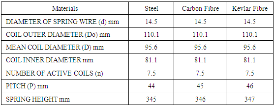
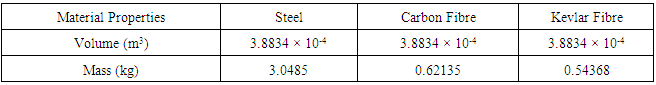
- The solid modeling of the compression helical spring is done using CREO parametric software. The characteristic parameter of the helical spring affects their behavior. The important dimension used for modeling the spring are wire diameter(d) and mean diameter(D), number of active loops(N) and the distance between two consecutive loops i.e. pitch(P). These are the parameters which affect the behavior of the spring. These parameters are shown figure 2. Steels, Carbon fiber and Kevlar Fiber are the spring materials used for the experimental comparative study. Dimensions of the spring for different materials are depicted in the table 1.
 | Figure 2. Coil Spring Model and its design parameters |
|
 | (1) |
 | (2) |
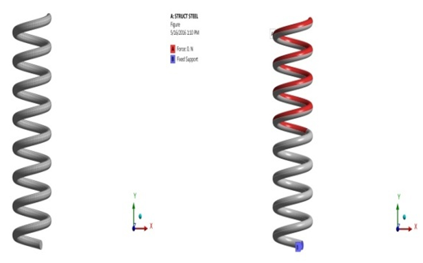 | Figure 3. Meshing of coil springs and load and boundary condition for coil spring |
|
3. Replacent of Composite Springs with Steel Spring
- The steel helical spring has been replaced by two different composite helical spring which includes carbon fabrics/resin and Kevlar fabric/resin. The load and boundary condition applied to the composite helical springs are similar to that of steel spring static structural analysis i.e. the spring is fixed at the bottom and the load is applied from the top which is the negative y-direction at load varying from 0 to 5 KN with 0.5 KN interval. The meshing is also similar to that of steel spring i.e. 5mm. The stress vs. strain graph and the load vs. defection graph are plotted. Both the graphs are linearly increasing.
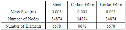
 | Figure 4. Maximum Deformation of Steel Coil Spring |
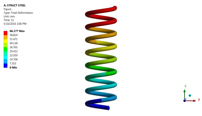
 | Figure 5. Equivalent Stress of Steel Coil Spring at 5KN |
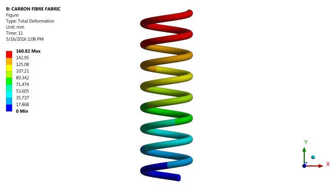 | Figure 6. Maximum Deformation of Carbon Fiber Fabric Coil Spring |
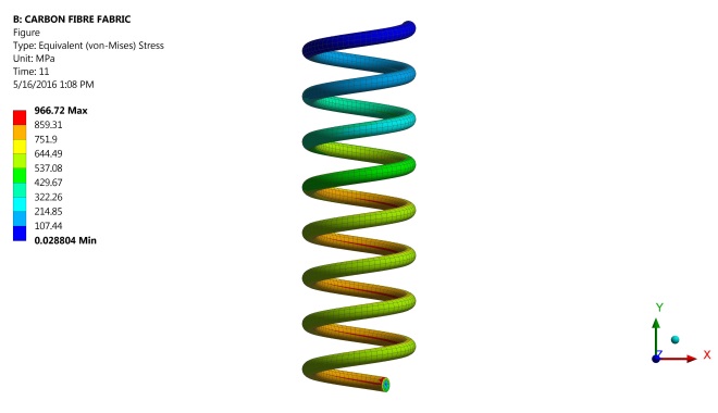 | Figure 7. Equivalent Stress of Carbon Fiber Fabric Coil Spring at 5KN |
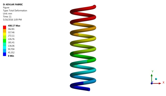 | Figure 8. Maximum Deformation of Kevlar Fabric Coil Spring |
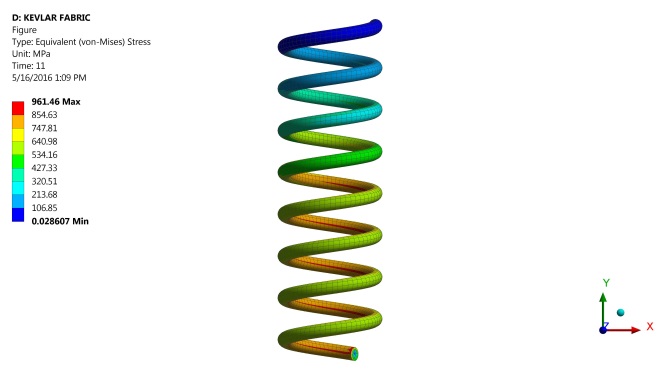 | Figure 9. Equivalent Stress of Kevlar Fabric Coil Spring at 5KN |
3.1. Weight of Composite Helical Spring
- The weight of steel spring is 3kg but after replacing the material property of the spring model to the composite materials the weight of the composite helical spring was drastically reduced. For carbon fabric the weight is 0.5 kg and for the Kevlar fabric/resin the weight is 0.6 kg. This drastic reduction of weight in helical spring can lead to very good stiffness to weight ratio which is the concluding factor in this project. The volume of the spring remains the same.
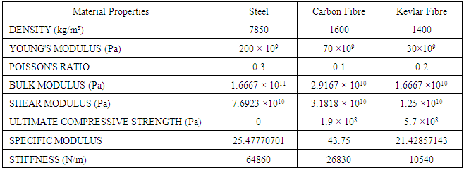
3.2. Stiffness to Weight Ratio or Specific Modulus
- Stiffness to weight ratio is the ratio of young’s modulus in GPa by mass density of the material in g/cc. The specific modulus of steel spring is 25.47 and the specific modulus for composite spring i.e. carbon fiber fabric spring is 43.75 and for Kevlar fabric spring is 21.42. The unit of specific modulus is young’s modulus upon mass density of the material.
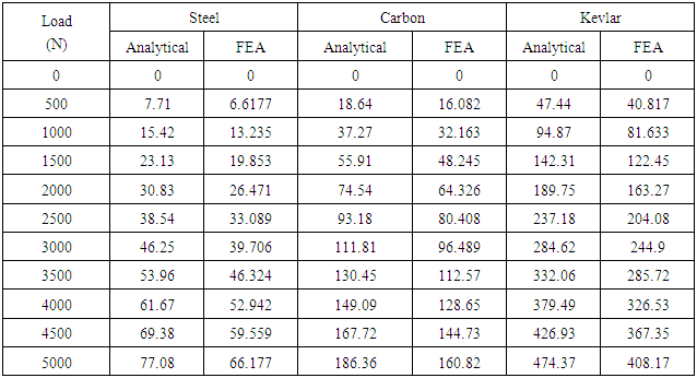
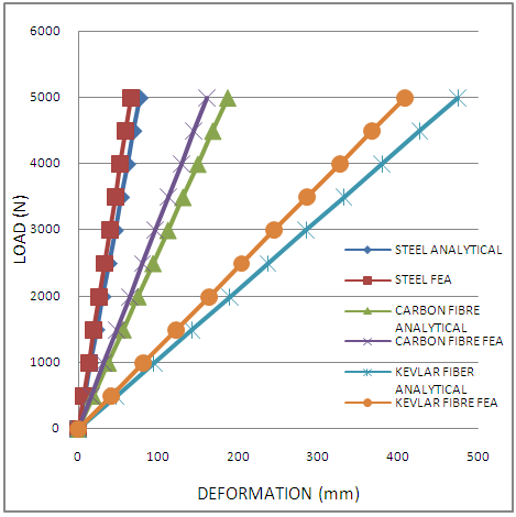
3.3. Load vs. Deflection Graph
- The graph of load vs. deflection was linearly increasing because the load applied from 0kN to 5kN with interval of 0.5kN. The deflection kept on increasing with the increase in load. The graph shows the deflection from analytical results and Finite Element Analysis result for all the three materials i.e. Steel, Carbon fiber fabric and Kevlar fabric.
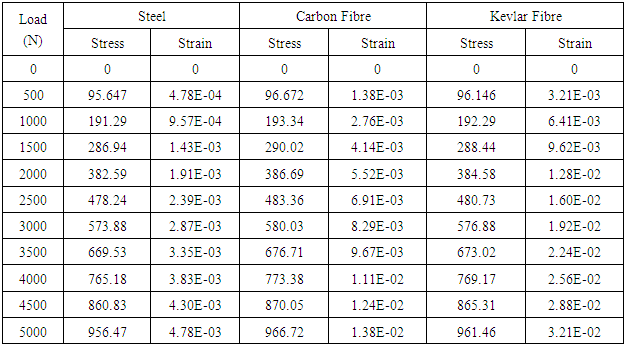
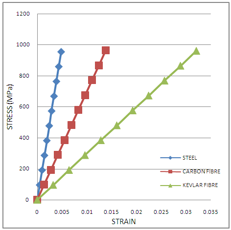
3.4. Stress vs Strain Graph
- The stress and strain graph for all the materials was linear. The stress is force upon area. Here the area is constant only the force applied ranges from 0 KN to 5 KN with an interval of 0.5 KN. As the force increases the stress also increases because they are directly proportional. This increase in the value of stress also leads to increase in the strain. Hence the graph plotted was linear shown in figure 10.
|
|
|
|
 | Figure 10. Load Vs Deflection Graph for Steel, Carbon Fiber Fabric and Kevlar Fabric Coil Spring |
 | Figure 11. Stress Vs Strain Graph for Steel, Carbon Fiber Fabric and Kevlar Fabric Coil Spring |
4. Results and Discussion
- The analysis of helical spring used in automobile was done on three different materials such as steel, carbon fiber fabric and Kevlar fabric. The mass of steel spring is 3.0 Kg as replaced with the composite materials the weight of the spring drastically reduces. Therefore the weight of the carbon fiber fabric spring is 0.6 Kg and the weight of Kevlar fabric spring is 0.5 Kg. Similarly the stiffness is 64860 N/m, 26830 N/m and 10540 N/m for steel, carbon and Kevlar spring respectively. The analytical values for the spring deflection were calculated numerically and the FEA results for the spring deflection was obtained using ANSYS workbench. The results obtained by these two methods were close enough with only around 13% error. The graphs for analytical and FEA are plotted in a single graph for all the materials to show the comparison for the ideal spring materials. The graph of stress and strain was linear due to the linear increase in the applied load. The stress strain graph for every material determines the relationship between stress and strain. The specific modulus of steel, carbon and Kevlar material is found to be 25.47, 48.75 and 21.429.
5. Conclusions
- From the results obtained by the analytical calculations and the FEA results were compared. The results are found to be similar with just 13% error. The specific modulus for steel material was 25.47 and for the Kevlar material was 21.42 and for the carbon material it was 43.75. Thus carbon has high stiffness to weight ratio compared to the other materials which makes it a concluding factor in deciding the type of material to be used for the manufacturing of the spring. Since the weight of the carbon is very low compared to the steel spring it is very beneficial to use carbon spring instead of steel spring to reduce the overall weight of the vehicle when used in automotive industries.