-
Paper Information
- Next Paper
- Previous Paper
- Paper Submission
-
Journal Information
- About This Journal
- Editorial Board
- Current Issue
- Archive
- Author Guidelines
- Contact Us
Journal of Mechanical Engineering and Automation
p-ISSN: 2163-2405 e-ISSN: 2163-2413
2016; 6(5A): 58-62
doi:10.5923/c.jmea.201601.11

Antifriction Bearing Diagnostics in a Manufacturing Industry – A Case Study
 Abstract
 Reference
 Full-Text PDF
 Full-text HTML
Syed Zeashan, Subhan Ali, Prashanth Pai M.
Department of Mechanical Engineering, P.A. College of Engineering, Mangaluru, India
Correspondence to: Prashanth Pai M., Department of Mechanical Engineering, P.A. College of Engineering, Mangaluru, India.
| Email: |  |
Copyright © 2016 Scientific & Academic Publishing. All Rights Reserved.
This work is licensed under the Creative Commons Attribution International License (CC BY).
http://creativecommons.org/licenses/by/4.0/

Plant machineries are designed to run under extremely harsh operating conditions, where a failure may be catastrophic in nature. In most of the industries, unplanned stoppages due to failures have a high economic impact on the cost of the process. Mechanical failures may include faults in bearings, misalignments, faults in gearbox, improper lubrication, etc. Bearing failure is one of the leading causes of breakdown in any rotating machinery. The bearing faults can be caused by material fatigue, overheating, harsh operating environments, contamination, corrosion, wrong installation, etc. The faults related to bearing do not cause immediate breakdown, they progress with time until they result in a critical failure of the machine. With the help of advanced diagnosis methods, it is possible to detect these faults in their early phase, before they result in catastrophic failure of the machine. Condition monitoring is one such technique which plays a vital role in providing higher availability of plant machinery by detecting problems before they result in a major breakdown. It is the process of monitoring a parameter of condition in machinery, such that a significant change is indicative of a developing failure. Analysis of the parameter for ongoing deterioration will help in taking suitable measures to avoid further deterioration. Vibration analysis is the most commonly used condition monitoring technique. Comparison of the vibration spectra of new equipment with the standards will provide the information required to make a decision when maintenance intervention is required. This work involves the application of condition monitoring technique (Vibration analysis) on the antifriction bearings of a critical machine in the CNC manufacturing unit located in Karnataka state.
Keywords: Antifriction bearings, Condition monitoring, Vibration analysis, Catastrophic, Bearing failure
Cite this paper: Syed Zeashan, Subhan Ali, Prashanth Pai M., Antifriction Bearing Diagnostics in a Manufacturing Industry – A Case Study, Journal of Mechanical Engineering and Automation, Vol. 6 No. 5A, 2016, pp. 58-62. doi: 10.5923/c.jmea.201601.11.
Article Outline
1. Introduction to Condition Monitoring
- Condition monitoring is the process of determining and understanding the condition of machinery while it is still in operation [1]. It plays a vital role in providing higher availability of plant machinery by detecting problems before they result in a major breakdown [2]. Vibration analysis is the most commonly used condition monitoring technique. Comparison of the vibration spectra of new equipment with the standards will provide the information required to make a decision when maintenance intervention is required [3]. The key to a successful condition monitoring programme includes - knowing what to listen for, how to interpret it and when to put this knowledge to use. Condition monitoring not only helps plant personnel reduce the possibility of catastrophic failure, but also allows them to order parts in advance, schedule manpower, and plan other repairs during the downtime [4]. The main condition monitoring techniques applied in the industrial sector are Vibration Analysis and diagnostics, Lubricant analysis, Acoustic emission (Airborne Ultrasound), Infrared thermography, Ultrasound testing (Material Thickness/Flaw Testing), and Motor Condition Monitoring and Motor current signature analysis (MCSA) [5]. This work involves the application of vibration analysis on the antifriction bearings of a critical machine in the CNC manufacturing unit located in Karnataka state.
2. Vibration Analysis in Antifriction Bearings
- Bearings are among the most important components in majority of machines and exacting demands are made upon their load carrying capacity and reliability. Hence, it is quite natural that bearings should have come to play such a prominent part and that over the years they have been the subject of extensive research. Bearing engineers generally use fatigue as the normal failure mode, on the assumption that the bearings are properly installed, operated and maintained [6]. Many bearings fail prematurely in service because of heavier loading than has been anticipated, inadequate or unsuitable lubrication, careless handling, ineffective sealing or fits that are too tight, with resultant insufficient internal bearing clearance. Each of these factors produces its own particular type of damage and leaves its own special imprint on the bearing. All these factors lead to an increase in bearing vibration and so condition monitoring has been used for many years to detect degrading bearings before they catastrophically fail, resulting in associated downtime costs or significant damage to other parts of the machine. Bearing manufacturers have developed vibration tests as an effective method for measuring quality of the bearing. A common approach is to mount the bearing on a quiet running spindle and measure the radial velocity at a point on the bearing’s outer ring in three frequency bands, 50-300, 300-1,800 and 1,800-10,000Hz [7]. The bearing must meet RMS (Root Mean Square) velocity limits in all three frequency bands. Vibration monitoring relies on the well-known characteristic vibration signatures which rolling bearings exhibit as the rolling surfaces degrade [8].
3. Sources of Vibration in Antifriction Bearings
- Antifriction bearings represent a complex vibration system whose components interact to generate complex vibration signatures. Antifriction bearings are manufactured using high precision machine tools and strict quality controls. In spite of this, they inevitably will have degrees of surface imperfections whose amplitudes are in the order of nanometers, significant vibrations can still be produced in the entire audible frequency range. Vibrations will be generated as the surfaces interact, through a combination of rolling and sliding [9]. Some of the sources of vibration in antifriction bearings are as follows:
3.1. Variable Compliance
- Bearing vibration is an inherent feature of antifriction bearings under radial and misaligning loads. This type of vibration is often referred to as ‘variable compliance’. It occurs because the external load is supported by a discrete number of rolling elements whose position with respect to the line of action of the load continually changes with time. It is heavily dependent on the number of rolling elements supporting the externally applied load. The greater the number of loaded rolling elements, the lesser is the vibration [10]. For radially loaded or misaligned bearings ‘running clearance’ determines the extent of the load region, and hence, variable compliance increases with clearance.
3.2. Geometrical Imperfections
- For axially loaded ball bearings operating under moderate speeds, the form and surface finish of the critical rolling surfaces are generally the largest source of noise and vibration. It is convenient to consider geometrical imperfections in terms of wavelength compared with the width of the rolling element-raceway contacts. Surface features of wavelength of the order of the contact width or less are termed roughness, whereas longer wavelength features are termed waviness. Waviness can produce vibration at frequencies up to around 300 times rotational speed but is usually predominant at frequencies below 60 times rotational speed. Any geometrical errors on the outside diameter of the shaft or bore of the housing can be reflected on the bearing raceways with the associated increase in vibration.
3.3. Surface Roughness and Discrete Defect
- Surface roughness is a significant source of vibration when its level is high compared with the lubricant film thickness generated between the rolling element-raceway contacts. The surface asperities can break through the lubricant film and interact with the opposing surface, resulting in metal-to-metal contact. The resulting vibration consists of a random sequence of small impulses, which excite all the natural modes of the bearing and supporting structure. Discrete defects refer to damage of the rolling surfaces due to assembly, contamination, operation, mounting, poor maintenance, etc. These defects can be extremely small and difficult to detect and can take a variety of forms: indentations, scratches along and across the rolling surfaces, pits, debris and particles in the lubricant.
3.4. Raceway Defect
- A discrete defect on the inner raceway will generate a series of high energy pulses at a rate equal to the ball pass frequency relative to the inner raceway. Because the inner ring is rotating, the defect will enter and leave the load zone causing a variation in the rolling element-raceway contact force, hence deflections. While in the load zone the amplitudes of the pulses will be highest, but then reduce as the defect leaves the load zone resulting in a signal, which is amplitude-modulated at inner ring rotational frequency. A discrete fault on the outer raceway will generate a series of high energy pulses at a rate equal to the ball pass frequency relative to the outer ring. Because the outer ring is stationary the amplitude of the pulse will remain theoretically the same hence will appear as a single discrete peak within the frequency domain.
3.5. Rolling Element Defect
- Defects on the rolling elements can generate a frequency at twice ball spin frequency and harmonics and the fundamental train frequency. Twice the rolling element spin frequency can be generated when the defect strikes both raceways, but sometimes the frequency may not be this high because the ball is not always in the load zone when the defect strikes and energy is lost as the signal passes through other structural interfaces as it strikes the inner raceway. Also, when a defect on a ball is orientated in the axial direction it will not always contact the inner and outer raceway and therefore may be difficult to detect.
3.6. Cage Defect
- The bearing cage has less mass and tends to rotate at typically 0.4 times inner ring speed. Therefore, unless there is a defect from the manufacturing process, is generally not visible [11]. In the case of cage failure, the signature is likely to have random bursts of vibration as the balls slide and the cage starts to wear or deform and a wide band of frequencies is likely to occur.
4. Vibration Measurement in Antifriction Bearings
- Vibration measurement can be generally characterized as falling into one of three categories – detection, diagnosis and prognosis [12]. In detection, the overall vibration level is measured on a broadband basis in a range for example, 10–1,000Hz or 10-10,000Hz. In machines where there is little vibration other than from the bearings, the spikiness of the vibration signal indicated by the Crest Factor (peak/RMS) may imply incipient defects, whereas the high energy level given by the RMS level may indicate severe defects. Generally, other than to the experienced operator, this type of measurement gives limited information but can be useful when used for trending, where an increasing vibration level is an indicator of a deteriorating machine condition. Trend analysis involves plotting the vibration level as a function of time and using this to predict when the machine must be taken out of service for repair. Frequency analysis is an improved diagnostic method, which usually gives a much earlier indication of the development of a fault and also the source of the fault. In the time domain the individual contributions e.g. unbalance, gears, etc. to the overall machine vibration are difficult to identify. In the frequency domain they become much easier to identify and can therefore be easily related to individual sources of vibration. A fault developing in a bearing will show up as increasing vibration at a characteristic frequency making detection possible at a much earlier stage than with overall vibration.Having detected and diagnosed a fault, the prognosis is much more difficult and often relies on the continued monitoring of the fault to determine a suitable time when the equipment can be taken out of service or relies on known experience with similar problems.
5. Experimentation (Spindle Vibration Test)
- The experimentation is carried out on the rolling element bearings of the selected critical machine named MAZAK FH 6800 in a reputed CNC machine manufacturing unit located in Karnataka. The bearing vibration analysis is conducted using a smart sensing instrument called as Smart Balancer. The Smart Balancer is a handy instrument for balancing installed rotors accurately and inexpensively without disassembling machines [13]. One can correct rotors of practically any size or weight on one and two levels (i.e., statically and dynamically) [14]. It makes use of the important diagnostic options such as measuring overall vibrations, tracking analysis and FFT frequency analysis of vibrations is also available. Its comprehensive equipment covers most of the other vibration measuring functions, making it a high-performance tool for machine diagnosis. Spindle vibration test using Smart Balancer is shown in figure 1.
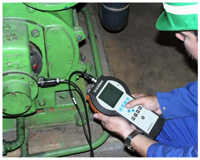 | Figure 1. Spindle Vibration Test using Smart Balancer |
5.1. Observations
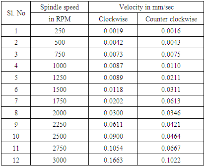
- Table 1 shows the vibration in mm/sec in both clockwise and counter clockwise directions for different spindle speeds. For analysis, the velocities for 1000 RPM is considered.
|
5.2. Results and Discussions
- The damage frequencies in rolling element bearings are calculated as shown below. Figure 2 shows the details of rolling element bearings.
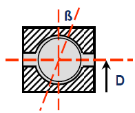 | Figure 2. Rolling element details to find out damage frequencies |
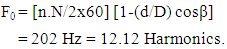 ii. Inner race damage frequency,
 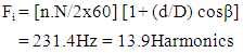 iii. Rolling element damage frequency,
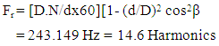 iv. Cage damage,
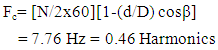
 Manufacturer of MAZAK FH 6800 recommends a safe vibration limit of 0.2mm/sec. By using the readings of Smart Balancer a graph of mm/s Vs harmonics is plotted (as shown in figure 3). It can be seen that the vibration levels are within the safe limit recommended by the manufacturer. Hence the bearing is found to be working within safe limits of vibration and hence can be continued in service.
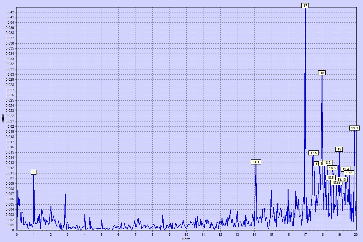 | Figure 3. Bearing analysis: mm/s Vs Harmonics for 1000RPM |
6. Conclusions
- The user has options to prevent the catastrophic failure of the bearings through inspection and preventive maintenance. Monitoring noise, vibration, temperature and lubrication can help to find problems before the occurrence of the failure. It is important to have personnel trained in bearing inspection and failure diagnosis to reduce downtime and correct bearing issues. When issues persist and field diagnostics cannot solve the problem, the bearing manufacturer can provide an in-depth investigation to determine the failure mode by using sophisticated laboratory equipment and experienced personnel who specialize in failure analysis. Once failure mode is determined, the bearing manufacturer can provide solutions to prevent future failures and extend bearing life.