-
Paper Information
- Next Paper
- Previous Paper
- Paper Submission
-
Journal Information
- About This Journal
- Editorial Board
- Current Issue
- Archive
- Author Guidelines
- Contact Us
Journal of Mechanical Engineering and Automation
p-ISSN: 2163-2405 e-ISSN: 2163-2413
2016; 6(5A): 49-53
doi:10.5923/c.jmea.201601.09

A Review on Tool Wear Monitoring System
 Abstract
 Reference
 Full-Text PDF
 Full-text HTML
Prashant Waydande, Nitin Ambhore, Satish Chinchanikar
Department of Mechanical Engineering, Vishwakarma Institute of Information Technology, Pune, India
Correspondence to: Prashant Waydande, Department of Mechanical Engineering, Vishwakarma Institute of Information Technology, Pune, India.
| Email: |  |
Copyright © 2016 Scientific & Academic Publishing. All Rights Reserved.
This work is licensed under the Creative Commons Attribution International License (CC BY).
http://creativecommons.org/licenses/by/4.0/

Tool wear is a major problem encountered in manufacturing industry during machining operations. A substantial work on online tool wear monitoring system has been reported in order to improve the quality of machining parts, to reduce the machine damage, and cost of machining. Researchers have made an effort to model the tool life, tool wear, and tool wear progression during hard turning by considering abrasion an adhesion and /or diffusion wear mechanisms. Experimental models (statistical-based), numerical attempts (Finite element method using Abaqus), and analytical based models are widely reported for soft and hard turning. This paper presents a review of studies on tool wear modeling as an attempt to develop tool condition monitoring system.
Keywords: Hard turning, Tool life, Tool wear
Cite this paper: Prashant Waydande, Nitin Ambhore, Satish Chinchanikar, A Review on Tool Wear Monitoring System, Journal of Mechanical Engineering and Automation, Vol. 6 No. 5A, 2016, pp. 49-53. doi: 10.5923/c.jmea.201601.09.
Article Outline
1. Introduction
- In the last few years, considering the need of metal cutting and manufacturing industry, numbers of researchers have worked on tool wear monitoring system for hard turning. In manufacturing industry, materials having hardness in between 45 to 70 HRC are considered as hard materials [1]. From users point of view in recent years there is an increasing demand of hard steel. Hence, the need to observed condition of tool wear during machining operation for hardened steels is important [2]. While machining of hardened steels polycrystalline cubic boron nitride (PCBN) and ceramic tools are mostly used for costly machining operations [3]. The popular cutting tool materials applied during high speed machining operation of hardened steel are sintered tungsten carbides (WC) and cubic boron nitrides (CBN) [4]. Hard turning is used in manufacturing industry as an economic alternative to grinding but reliability of hard turning process is often unpredictable. Although grinding is known to produce good surface finish at relatively high feed rates, hard turning can produce as good or better surface finish at significantly higher material removal rates [5]. Tool wear monitoring system can be effectively applied to machining operation like turning, boring, drilling, facing, forming, milling and shaping. Tools can be classified into two categories single point tool which have one cutting part (turning, shaping), multi point tool (drilling, milling) which have more than one cutting part [6]. This paper deals with recent advancement in tool wear monitoring systems during hard turning.There are several types of observed cutting tool wear which are listed below:1. Crater wears which occurs on rake surface. Crater wear can increase the working rake angle and reduce the cutting force, but it will also weaken the strength of cutting edge. 2. Flank wear which occurs on the flank face due to friction between machined surface of workpiece and tool flank. Flank wear is mainly caused by the rubbing action of the tool on the machined surface.3. Notch wears is special type of combined flank and rake face wear which occurs adjacent to the point where the major cutting edge intersects the work surface.
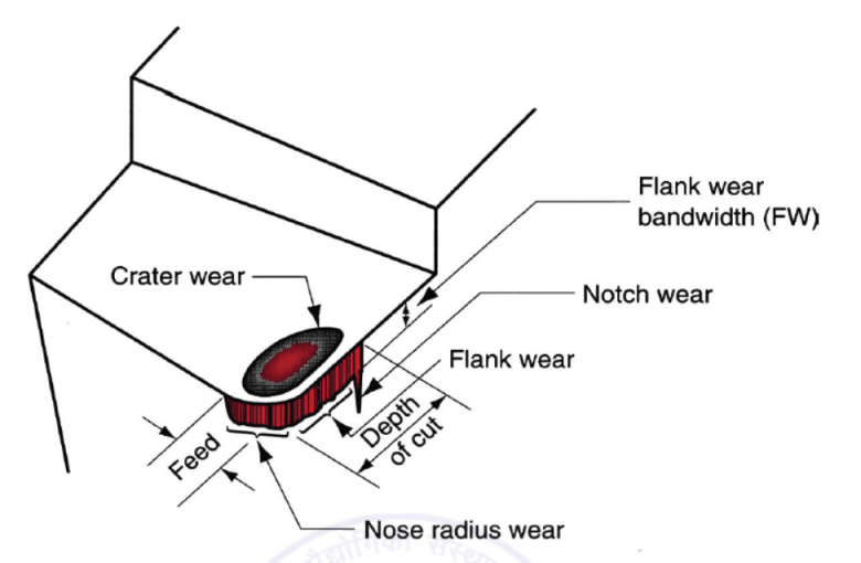 | Figure 1. Types of tool wear [23] |
2. Tool Wear Monitoring System
- Tool wear is the most undesirable characteristics of machining process as it’s adversely affect the tool life, which also has impact on dimensional accuracy, surface quality and consequently, the economics of machining operations. Hence, tool wear monitoring is necessary. With effective monitoring system, warn tool can be change in time to avoid production time and scrapped components [11, 12]. Analysis of the monitoring signals is most crucial factor in development of tool wear monitoring during hard turning, because it helps to achieve effective results [13].Indirect sensor based tool wear monitoring system works in three steps i) data or signal acquisition ii) signal processing and analysing and iii) resulted tool condition. In this, signal processing is an important step. In signal processing there are two steps, pre-processing and post processing. Different hardware such as, model like amplifiers, filters etc. are considered in pre-processing of signal. In post processing comparative method like Root Mean Square (RMS), Fast Fourier Transformation (FFT), time– frequency domain, statistical analysis etc. have been used to signal processing [14]. A block diagram of tool condition monitoring process is given in Figure 2.
 | Figure 2. Block diagram of TCMS |
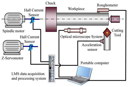 | Figure 3. Schematic diagram of TCMS [31] |
3. Measurement of Process Parameters
- There are number of process parameters used to measure tool wear in TCMS. Most commonly used parameters are cutting forces, vibration signals, surface roughness, tool wear. The brief review of this process parameter is given below.
3.1. Cutting Force Measurement
- It has been observed that variation in the cutting force can be correlated to tool wear. Gradual increase in tool wear during the cutting process causes the cutting forces to increase therefore the cutting forces is generally considered one of the most significant indicators of tool wear in the metal cutting process. Dynamometer is used for the measurement of cutting forces. Many researchers have investigated the effect of cutting force on tool wear during hard turning. Ghani et al. [9] studied that effect of tool wear on tool life, surface quality and production time and developed online tool wear measurement and monitoring system, using a low-cost sensor technique and user friendly GUI. MATLAB software was used develop a user-friendly graphical user interface (GUI) for online monitoring purposes. In experimental process two-channel strain gauge at tool holder was used to measure deflections in both tangential and feed direction. Result shows that developed online monitoring system, using the strain gauge signal, is an effective method of detecting the progression of flank wear width during machining. This is an efficient and low-cost method which can be used in then real machining industry to predict the level of wear in the cutting tool. Bartarya and Choudhury [15] studied the effect of cutting parameters and cutting force during hard turning of AISI 52100 grade steel. To test the quality of fit of data, they used ANOVA analysis method. They used AISI 52100 material of harness 60±2 HRC. Due to high hardness uncoated CBN tool was used for turning operation. The results revealed that depth of cut was found to be the most influential parameter affecting the three cutting forces followed by the feed rate. Fnides et al. [16] works on hard steel with grade X38CrMoV5-1. The machining was carried out on grade X38CrMoV5-1 steel. It has hardness value of 50 HRC. Mixed ceramic (CC650) was used as cutting tool insert and studied the effect of cutting speed, feed rate and depth of cut on cutting forces and surface roughness. Observed that tangential force is very sensitive for tool wear and depth of cut was most crucial parameter for tool wear progression.
3.2. Measurement of Vibration Signals
- Vibration signals are also one of the most important parameter for measurement of tool wear because they provide thorough insight in metal cutting process. Many researchers have worked on vibration signals induced during machining of hard material. Accelerometers are used to measure vibration signals. Researchers used tri-axial accelerometer to measure vibration signals in all three mutually perpendicular directions (feed, radial and thrust). Dimla et al. [6] measure vibration signals in three mutually perpendicular directions using Kistler mini accelerometers (type 8730A). Investigation showed that vertical component (z-direction) of both cutting forces and the vibration signals were the most sensitive to tool wear. The results indicated that the magnitudes of the static cutting forces were enormously dependent on the cutting conditions especially the DOC and feed-rate. Abouelatta and Madl [17] studied correlation between surface roughness and cutting vibration in turning process. Surtronic 3+ surface roughness tester was used to measure surface roughness and FFT Spectrum Analyser were used to measure vibration signals in radial and feed direction by using 3D accelerometer sensors. Finally the measured results were analysed by commercial software MATALAB, BC++, SPSS. Wang et al. [18] monitored vibration signals and used them using v support vector machine to develop tool condition monitoring system.
3.3. Surface Roughness Measurement
- Surface roughness and dimensional accuracy play very important role while performing machining operation. Poor surface finish may affect the performance of machining process. High cutting forces and high localized temperatures may dramatically affect the surface roughness. Cutting conditions has a considerable effect on surface roughness. Cemal et al. [24] studied effect of cutting parameters (cutting speed, feed rate and depth of cut) on surface roughness. Mathematical model was developed by using the data gathered from a series of turning experiments performed. Experiments were carried out on cold-work tool steel AISI P20 with CNMG 120408 coated carbide inserts. A result indicates that feed rate has greatest influence, followed by cutting speed on finishing of workpiece. Higher feed rates lead to higher surface roughness values. Asilturk and Akkus [25] studied the effect of cutting parameters on surface roughness in hard turning using the Taguchi method. Experiments have been conducted on AISI 4140 (51 HRC) using the L9 orthogonal array in a CNC turning machine under dry cutting condition. Coated carbide cutting tools were used as cutting tool inserts. Analysis of variance (ANOVA) was applied to investigate effects of cutting speed, feed rate and depth of cut on surface roughness. Results indicated that the feed rate has the most significant effect on Ra and Rz. According to the ANOVA analysis, the feed rate has an effect on Ra and Rz at a reliability level of 95%. Fnides et al. [16] observed that surface roughness is very sensitive to the variation of feed rate and that flank wear has a great influence on the evolution of cutting force components and on the criteria of surface roughness. Ozel and Karpat [19] measured surface roughness and tool flank wear of hard turning. The result shows that a decrease in the feed rate resulted in better surface roughness but slightly faster tool wear development, and increasing cutting speed resulted in significant increase in tool wear development but resulted in better surface roughness. Increase in the workpiece hardness resulted in better surface roughness but higher tool wear.
3.4. Measurement of Tool Wear
- Carrying on the machining process with a worn tool, increases the friction between the tool and the work piece, also causes poor surface finish therefore progression of tool wear is need to be monitored. Chinchanikar and Choudhury [20] studied effect of work material hardness and cutting parameters on performance of coated carbide tool when machining of AISI 4340 steel and observed the effect of cutting conditions on cutting forces, surface roughness and tool life by multiple linear regression models. Correlation coefficients were found close to 0.9. Highly significant parameters were determined by performing an Analysis of Variance (ANOVA). Analysis of the results concluded that the use of lower feed value, lower depth of cut and by limiting the cutting speed to 235 and 144 m/min; while turning 35 HRC and 45 HRC work material, respectively, ensures minimum cutting forces, surface roughness and better tool life. Experimental observations indicate that all the three components of cutting forces are higher for harder work material. Grzesik and Zalisz [21] investigated the wear phenomenon of hard material using ceramic tool. AISI 5140 steel (60 HRC) was used as a workpiece material. Cutting condition used for performing finishing cuts are constant cutting speed of 100 m/min with varying feed rate and small depth of cut of 0.2 mm. Experimental observations indicate that depending on the mechanical and thermal conditions generated on the wear zones, the wear mechanisms involve abrasion, fracture, plastic flow, material transfer and tribochemical. Dogra, Sharma et al. [22] compared CBN cutting tool insert with coated carbide cutting tool insert and cryogenically treated coated carbide cutting tool insert during machining of hardened AISI H11 steel (48-49 HRC). Results concluded that the flank wear of CBN cutting tool insert is lower as compared to other inserts.
3.5. Other Methods
- Various other parameters have been used by researchers to monitor tool wear condition, which mainly includes temperature [26, 27], Motor current and power measurement [28, 29], Acoustic emission [30] etc.
4. Summary
- Hard materials are mostly used in manufacturing industries such as bearings, gear and automotive industries. Material of hardness in the range of 45-70 HRC is considered as hard material. During machining of hard material the cutting tool is subjected to heavy mechanical loads and it is exposed to very high temperature due to excessive heat generation, therefore cutting tool material such as coated carbide, ceramics, CBN tools mostly used while performing turning operation under required machining condition. Geometry of cutting tool, hardness of workpiece material and cutting parameters affects the cutting forces, vibration signals, surface roughness and tool wear. Finally it is concluded that the process parameters cutting force, vibration signals and surface roughness can be used to predict the progression of tool wear during hard machining.