Sushmita1, M. Rajesh2, Hemanth K.2, Ravikantha Prabhu1, Sharath Meloth C.1, Binu K. G.1
1Department of Mechanical Engineering, St Joseph Engineering College, Vamanjoor, India
2Department of Mechanical Engineering, NITK, Surathkal, India
Correspondence to: Binu K. G., Department of Mechanical Engineering, St Joseph Engineering College, Vamanjoor, India.
| Email: |  |
Copyright © 2016 Scientific & Academic Publishing. All Rights Reserved.
This work is licensed under the Creative Commons Attribution International License (CC BY).
http://creativecommons.org/licenses/by/4.0/

Abstract
Natural fibers due to their low cost, high specific strength, recyclability, and environmental friendliness, are finding increasing applications in automotive, aerospace, bio-medical, and sports equipment. In the present work, hybrid sandwich composites using Jute and Glass fibers in Polyester polymer, namely: Jute-Glass-Jute (JGJ) and Glass-Jute-Glass (GJG), were prepared by curing under pressure using compression moulding technique. The prepared sandwich composites were subjected to tensile and flexural testing. Their vibration and damping characteristics were studied using free vibration and forced vibration test rigs. Further, the influence of using Magneto Rheological (MR) fluid on vibration damping properties of the composite samples have also been investigated. The tensile and flexural strengths of GJG composites were found to be higher than that of JGJ and plain jute composites. In terms of their free vibration response, JGJ composites showed slightly higher natural frequency for first 3 modes while GJG showed better damping factors. Under forced vibration test, the effect of MR fluid was observed to be better for JGJ composites which showed 8% higher reduction in amplitude in comparison to GJG composites.
Keywords:
Natural Fibres, Hybrid sandwich composite, Modal analysis, MR fluid
Cite this paper: Sushmita, M. Rajesh, Hemanth K., Ravikantha Prabhu, Sharath Meloth C., Binu K. G., Processing and Testing of Hybrid Sandwich Composites for Vibration Damping and Mechanical Properties, Journal of Mechanical Engineering and Automation, Vol. 6 No. 5A, 2016, pp. 22-27. doi: 10.5923/c.jmea.201601.05.
1. Introduction
In the last 20 years, natural fibers have received more attention from the materials research community worldwide. These fibers are considered to be excellent alternatives to synthetic fibers due to advantages such as: low cost, low density, high strength to weight ratio, recyclability, and better environmental performance. These enhanced properties have led to the increased use of natural fiber reinforced composites in the fields of aircraft, military, home appliances, automotive or transportation, civil infrastructure, construction, corrosion resistant equipment, electrical gadgets, biomedical fields and sports equipment etc.K Senthil Kumar et al. [1] carried out experiments using impulse hammer method to analyze the vibration and damping characteristics of banana fiber polyester composite(BFPC) and sisal fiber polyester composite(SFPC). Experimental investigations showed that SFPC due to its dispersion ability offers good mechanical bonding and hence exhibits better mechanical strength and free vibration properties compared to BFPC. Akash D A et al. [2] investigated the damping factors and the mode shapes for the cantilevered rectangular symmetric plate of hybrid jute-sisal fabric reinforced polyester composite with different fiber orientations using FFT based spectrum analyzer. It was found that the average damping factor obtained for fundamental frequency of hybrid jute-sisal laminate is 1.15 times higher than that of jute laminate. Iqbal Mokhtar et al. [3] carried out experiments to characterize the mechanical behavior of basalt/HDPE composite under in-vitro condition. The study indicated that the synthetic fiber (carbon) combines well with HDPE as a composite material and gave excellent consistent performance in mechanical testing. Also the basalt fibre as a natural fibre showed good results and better than E-glass fibre in overall mechanical evaluation.
1.1. Vibration and Damping
Vibration is the motion of a particle or a body or system of connected bodies displaced from a position of equilibrium. Most vibrations are undesirable and particularly in machines and structures because they produce increased stresses, energy losses, cause added wear, increase bearing loads, induce fatigue, create passenger discomfort in vehicles, and absorb energy from the system. Damping is the resistance offered by a body to the motion of a vibratory system. The resistance may be internal or external and externally through a liquid or solid. The main advantage of providing damping in mechanical systems is to control the amplitude of vibration so that the failure occurring due to resonance could be avoided. Vibration damping plays an important role in machines and structures by improving performance and stability, reducing noise and increasing lifetime.
1.2. FRF (Frequency Response Function)
The FRF is the measure of any system output spectrum in response to an input signal. A linear system such as Single degree of freedom (SDOF) or Multi degree of freedom (MDOF), when subjected to sinusoidal excitation will give sinusoidal response at the same frequency and at specific amplitude that is characteristic to the frequency of excitation. The phase difference between the response and the excitation will vary with frequency. The characteristics of a system that describes its response to excitation as a function of frequency is the frequency response function. It is defined as the ratio of the output to the input as a function of frequency. Accelerometer measures the vibration levels at several points on the structure and signal analyser computes the FRF.
1.3. Modal Analysis
Modal analysis is a worldwide used methodology that allows fast and reliable identification of system dynamics in complex structures. In the last decade several methods have been developed in quest to improve accuracy of modal models extracted from test data and to enlarge the applicability of modal analysis in industrial context. Structures vibrate in special shapes called mode shapes when excited at their resonant frequencies. A mode shape is the characteristics deformation shape defined by relative amplitudes of the extreme positions of vibration of a system at a single natural frequency. The modal parameters are the natural frequencies, damping ratios and modal masses associated with each of the mode shapes. Under normal operating conditions, the structure will vibrate in a complex combination of all the mode shapes. Modal analysis refers to measuring and predicting the mode shapes and frequencies of a structure.
1.4. Magnetorheological Fluid
Magnetorheological (MR) materials consist of micron size particles which are magnetically permeable and suspended in a non- magnetic medium. When a magnetic field is applied, the rheological properties of these materials are rapidly and reversibly altered. The mechanism responsible for this bulk effect is the induced magnetic interaction of the particles within the matrix. In MR fluids, the mutual interaction amongst the particles causes the formation of chain-like structures aligned roughly parallel to the applied magnetic field. This transforms the MR fluid into a semi-solid cluster like structure. Because of this more energy is required to shear that cluster. The mechanism of MR fluid is shown in figure 1.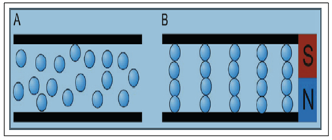 | Figure 1. Mechanism of MR fluid |
2. Experimental Details
In this study jute and glass fibers were used as reinforcement material in woven form. Unsaturated isophthalic polyester resin and Methyl Ethyl Ketone Peroxide (MEKP) hardener with a weight ratio of 100:1 were used as matrix material. The resin and hardener were purchased from Vasavibala resins Ltd., Chennai, India.
2.1. Composite Preparation
Composite laminates were prepared with a dimension of 270mm x 250mm x 3mm using compression moulding technique. Wax was applied to the metal mould for the easy removal of the composite after curing. Initially 250g of resin, 2.5ml catalyst and accelerator each were mixed properly. A little amount of this mixture was poured inside the mould. Then one fibre mat was placed over the poured resin and again resin is poured over it. Similarly two more layers are laid. After this the covering plate was placed over the mould and compressed hydraulically at a temperature of 80ºC and compression pressure of 100 bars for half an hour. Later the mould is cooled and the composite was separated from it. Four composites each of GJG and JGJ combination were prepared. Figure. 2 shows the curing of specimen.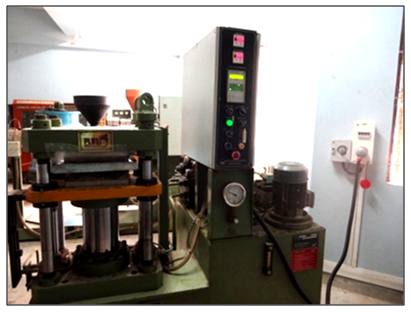 | Figure 2. Curing process setup |
2.2. Density Determination
Density of polyester composite was measured using Archimedes principle according to the ASTM standards D 792-08. The density of a solid is a property that is measured to identify how a material follows physical changes, to indicate degree of uniformity. In this work, the density is measured to determine the effect of number of layers of each reinforcement and also to confirm presence of porosity in the prepared sample. The test method is as follows. The mass of a specimen is determined in air. The sample is then immersed in a liquid (water), its apparent mass upon immersion is determined, and its specific gravity (relative density) calculated using the equation given below.  | (3) |
A = apparent mass of specimen in air (g).B = apparent mass of specimen immersed in water (g).
2.3. Tensile and Flexural Test
Tensile and Flexural tests were conducted in (Tinius Olsen) a universal testing machine according to the ASTM standards (ASTM: D638). The dumbbell shape tensile specimens were cut from the laminates prepared with dimensions of 165mm x 13mm x 3mm. In flexural testing, three-point bending was performed at room temperature on a specimen of 127mm x 12.7mm x 3mm dimension. The cross head speed was selected as 5mm/min. Figure 3 shows the tensile and flexural test setups. 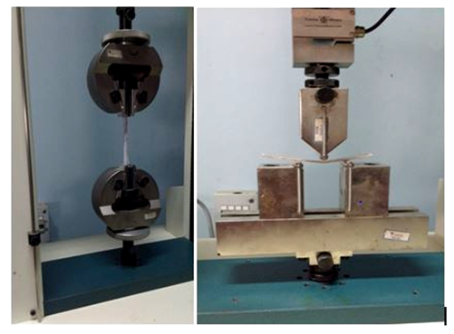 | Figure 3. Tensile and Flexural test setups |
2.4. Free Vibration Test - Modal Analysis
For the free vibration test the laminates were cut into rectangular beams of dimension 170mm x 17mm x 3mm. Modal analysis was performed in a free vibration test rig with the help of an impact hammer test. The schematic diagram is shown in Figure 4. The setup comprised of impact hammer with a sharp hardened tip (Kistler model 9722A2000, sensitivity 10.24mV/g), and accelerometer (sensitivity 10.84mV/g) attached to the end of the rectangular composite laminate with wax. The displacement signal from the accelerometer was recorded in a PC using Data Acquisition System (DAQ) and ICP conditioner. The time domain data is then converted into frequency domain using Fast Fourier Transforms (FFT).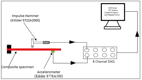 | Figure 4. Vibration test line diagram [4] |
2.5. Preparation of MR Fluid
Silicon oil was first mixed with grease in very small concentrations using a mechanical stirrer. This mixing process was performed for 1 hour continuously till the grease particles were dissolved and suspended in the silicon oil. After the solution was prepared, the required weighed iron powder was poured into it in parts while the stirring was carried out. As the iron powder got mixed along with the solution it became highly viscous and appeared black in colour. This stirring was carried out for an hour and the end result was obtained result obtained was MR Fluid as seen in the Figure 5.  | Figure 5. Prepared MR fluid [5] |
2.6. Composite Preparation for Forced Vibration Test
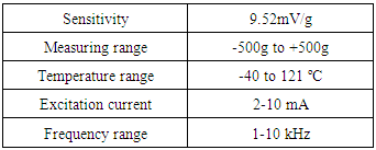
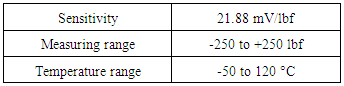
The forced vibration is carried out on composite laminate plates of 270mm x 250mm x 3mm. Two plates were sandwiched using araldite gum with Silicon oil carbonyl iron particle based magnetorheological (MR) fluid injected between them. An electromagnetic shaker is used to give the forced excitations to the cantilever sandwich plate. The displacement signals were recorded in a data acquisition system and analysed using Lab view software. A magnetic field of strength 0.1 tesla is used for the testing. Figure 6 shows the forced vibration test rig. The specifications of accelerometer and load cell used in the analysis are given in the Table 1 and Table 2 respectively. 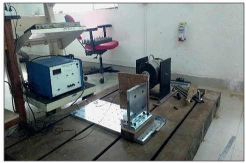 | Figure 6. Forced Vibration Test Rig |
Table 1. Specifications of Accelerometer
 |
| |
|
Table 2. Specifications of Load cell
 |
| |
|
3. Results and Discussions
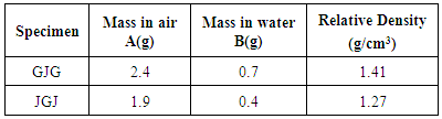
3.1. Composite Density
The density of the new composite was found out using Archimedes principle as described earlier. The results are tabulated in the table 3.Table 3. Density of Composites
 |
| |
|
The density value of GJG composite was found to be high compared to JGJ composite. Because the density of Glass (2.55g/cm3) is much higher than that of Jute (1.46g/cm3). Hence it may be inferred that the composite preparation was successful in terms of mould filling and curing under pressure.
3.2. Tensile Modulus
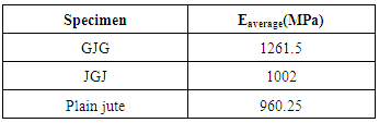
From the tensile test results it was found that the average value of Young's modulus (E) of GJG specimen was greater when compared to JGJ and plain jute specimens. Values are shown in the table 4. Table 4. Tensile Test Results
 |
| |
|
Graphs of stress versus strain % were plotted for all specimens. The graphs showed the trend of decreasing value of E in the order GJG, JGJ and plain jute as shown in Figure 7.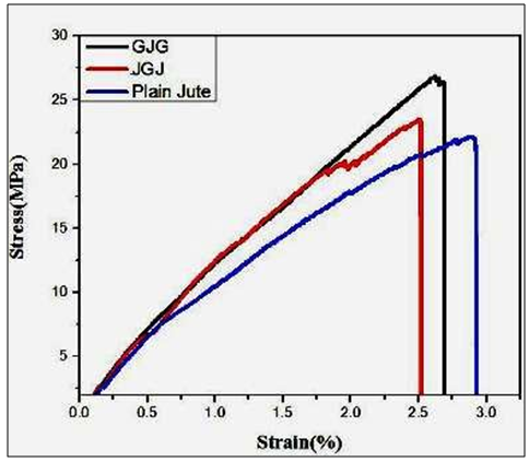 | Figure 7. Tensile test stress - % strain graph |
The Young's modulus from a stress –strain graph can be obtained by calculating the slope. It can be observed from the above graph that the slope of GJG plot is highest followed by JGJ and plain jute. Thus by comparing the values of Young's modulus, we can conclude that GJG composite material is the strongest among the three. This is because the Young's modulus of Glass (73GPa) is greater than that of Jute (10-30GPa). As the strength of a material is directly proportional to Young's modulus, the increase in glass fibre content imparts more strength to the material. Since GJG has more glass content, it is stronger compared to other two materials.
3.3. Flexural Modulus
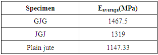
From the flexural test results. It was found that the average value of Flexural modulus (G) of GJG specimen was greater when compared to JGJ and plain jute specimens. Values are shown in the table 5. Table 5. Flexural Test Results
 |
| |
|
Graphs of stress versus percentage strain were plotted for all specimens. As shown in the Figure 8 there is a trend of decreasing value of G in the order GJG, JGJ and plain jute.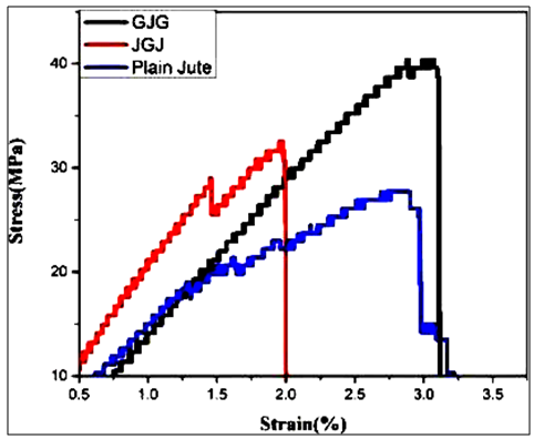 | Figure 8. Flexural test stress - % strain graph |
The Flexural modulus of GJG is greater than JGJ and plain jute as observed from the stress – strain graph shown above. This can be explained from the fact that the flexural modulus of glass (26 GPa) is greater than that of Jute (3-8 GPa). As the content of glass is more in GJG composite, its flexural modulus increases and hence the bending strength.
3.4. Free Vibration Properties
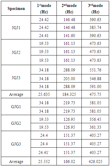
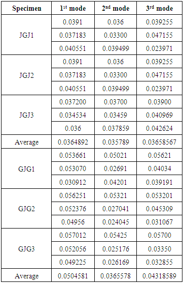
Frequency and damping values for First 3 modes are show in Table 6 and Table 7 respectively. From the table it was observed that, the average value of 1st, 2nd and 3rd natural frequency of JGJ composite was found to be 25.635Hz, 184.325Hz and 475.75Hz. The corresponding modal damping values are 0.0364892, 0.035789 and 0.03658567 respectively. The natural frequency values of GJG composites are 25.552Hz, 166.02Hz and 426.025Hz.The corresponding damping factors are 0.0504581, 0.03655789 and 0.04318589 respectively. Table 6. Natural frequency
 |
| |
|
Table 7. Damping factors
 |
| |
|
It was observed that the natural frequency of JGJ composite is slightly higher than the GJG composite in all the 3 modes of vibration. But the GJG samples show better damping properties compared to the JGJ composites. Since the porosity of a material is one of the deciding factors for damping property we can say that inherent porous cross sections of the natural fibres are responsible for offering high damping properties in this particular study.
3.5. Forced Vibration Properties
Sandwich plates of GJG and JGJ composites filled with MR fluids were fixed to the forced vibration test rig (cantilever boundary condition). Forced vibrations were induced using an electromagnetic shaker. The results obtained were plotted as shown in figure 9 and figure 10 respectively. It was observed that when the external force frequency is equivalent to the natural frequency of the composites the amplitude becomes maximum as shown in the graph. This phenomenon is called as Resonance. The amplitude of vibrations at resonance is maximum in JGJ compared to the GJG. This shows the higher damping factor of the GJG compared to the JGJ composites. The same results were obtained in the free vibration tests also.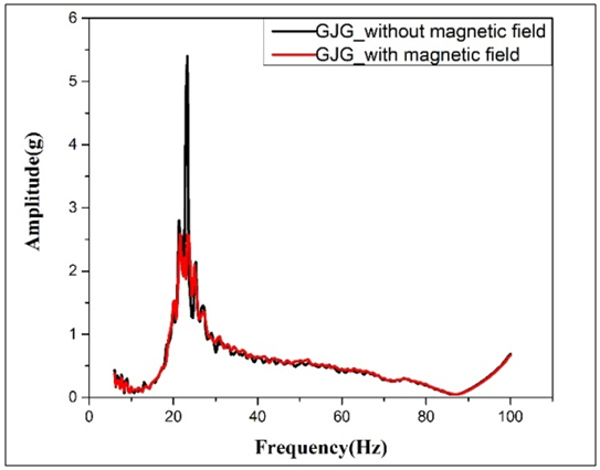 | Figure 9. FRF spectrum of GJG composite |
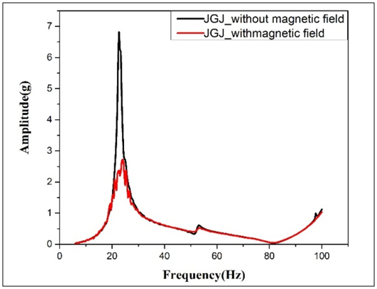 | Figure 10. FRF spectrum of JGJ composite</ |

 Abstract
 Reference
 Full-Text PDF
 Full-text HTML