Sujay Hegde , B S Suresh
Department of Mechanical Engineering, BMS College of Engineering, Bengaluru, India
Correspondence to: Sujay Hegde , Department of Mechanical Engineering, BMS College of Engineering, Bengaluru, India.
| Email: |  |
Copyright © 2015 Scientific & Academic Publishing. All Rights Reserved.
Abstract
In the automotive industry, brake noise is gaining lot of concern and thus has led to extensive research in this field. The brake noise is considered as a discomfort by the passenger and is a failure state in the eye of the manufacturer. The audible noise generated can be related to physical vibrations occurring in the system which is termed as stick-slip effect. Thus understanding this class of vibration, which is generally friction induced by having the friction coefficient varying with relative speed, is necessary to eliminate brake noise. This paper attempts to study the oscillation between the brake pad and disc using a simple 1-DOF model. In thus study, stick-slip phenomenon is simulated and studied by using complex non-linear friction laws and contacts between a mass and moving belt. Also, a parametric study is conducted to study the effect of mass, spring and friction parameters on the stick-slip effect. A transient multi-body simulation is conducted on a simple 1DOF model to simulate and study the stick-slip phenomenon, which includes non-linear friction law and multi-point contacts using LMS Virtual Lab.
Keywords:
Stick-Slip, Friction induced vibration, Transient analysis, Multi-Body Simulation
Cite this paper: Sujay Hegde , B S Suresh , Study of Friction Induced Stick-Slip Phenomenon in a Minimal Disc Brake Model, Journal of Mechanical Engineering and Automation, Vol. 5 No. B, 2015, pp. 100-106. doi: 10.5923/c.jmea.201502.20.
1. Introduction
Brakes are one of the most vital and crucial safety features in an automobile where the main focus is on the performance and functioning of the brake. However, automotive brake noise has become an issue for component manufacturers as vehicle comfort has become such an important factor to indicate the quality of a passenger car. Audible noise also contributes to environmental pollution, especially in urban areas, and is regarded by vehicle users as an indication of a fault in the braking system which in turn is realized as a failure state by the manufacturers. Large amount of money is being spent on the warranty and repair costs occurring due to the brake noise and vibration issue as the failure state has to be covered under the vehicle’s warranty [1].Investigation into brake noise has been conducted by various experimental and analytic methods. Experimental methods, for all their advantages, are expensive mainly due to hardware cost and complexity in design iterations. Experimental studies on disc brake noise can provide substantially accurate solutions, provided with some assumptions, simplifications and can also provide critical improvements or modifications to resolve this problem over several tests and iterations which requires substantial amount of time and resources. An alternate and current method to arrive at the solution is the numerical methods using computer software tools. This method is fairly accurate but needs to be validated beforehand to ensure the validity of the solutions obtained. Simulations are therefore preferred and emphasized during the pre-development stages. Simulation and analysis methods may be divided into two big categories: complex eigenvalue analysis in the frequency domain and transient analysis in the time domain which is gaining momentum over experimental method for their capabilities.During disc brake engagement, the brake lining rubs against the rotor and the kinetic energy is dissipated in the related friction process as heat. This kinetic energy is transferred into the energy of the contact asperities, particles, and atoms. Then, the energy of the motion of asperities, particles, and atoms translates into vibration and generates a sound wave [2]. This paper focuses on the non-linear dynamic transient analysis of brake vibration with a multi-body dynamic simulation in order to study and simulate the stick-slip process in depth. New excitation mechanisms such as Coulomb’s friction law and enhanced contact mechanics are implemented. The multi-body dynamic simulation model includes a simple mass-spring-belt system which can be considered as simplified 1-DOF model where the mass represents the brake pad and belt represents the disc brake and the spring represents the stiffness of the system. The main goal is to observe and simulate stick-slip phenomenon with the implementation of a velocity dependent friction law between the brake pad and the brake disc when in contact.
2. Friction Induced Vibration
Almost all types of vibration and noise problem in brakes are generally considered to be friction induced including brake squeal and brake groan. The most useful classification can be done by distinguishing force-excited from self-excited vibrations and by locating the appearing vibration frequencies on a frequency scale as shown in Figure 1.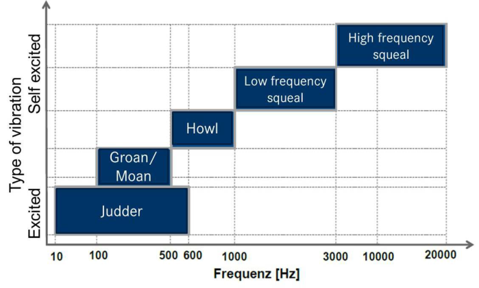 | Figure 1. Classification of Noise |
Brake squeal is the result of friction-induced vibration. It is perceived in the form of tonal sounds [3]. The fundamental frequency of tone is in the range of 1 kHz to 12 kHz. As Day [1] states, groan is a semi-resonant vibration, typically < 200 Hz, which is most prevalent at lower speeds and is considered to be caused by “stick-slip” arising from a negative friction-velocity characteristic.Conceptually, friction-induced vibration can be accomplished only when force-oscillations are accompanied by motion oscillations along the direction of the force oscillations with a suitable relative phase. That means, all type of brake noise originates as a self-excited oscillation which is the stick-slip phenomenon. The simplest and most well-known way to generate such a situation appears, when the coefficient of sliding friction decreases with relative sliding velocity [3]. Thus an appropriate friction law that encompasses the above criteria must be chosen.
2.1. Transient Analysis
Transient analysis need not make important theoretical assumptions underlying the complex eigenvalue analysis such as constant contact area between pad and disc, linear friction laws etc. The non-linear transient method can analyse the effect of time-dependent loads and functions as well as perform a stability analysis. The solutions are appropriate for situations that are far from the equilibrium position or when nonlinearities exist in the system. It allows simulating operating conditions by running the nonlinear transient process from the initial state to steady state [4]. The frequency content can be extracted from the time series by applying an FFT (Fast Fourier Transform) principle. FFT is an algorithm that converts time domain data to frequency domain.The main advantage of implementing this process is that, it allows sophisticated nonlinear friction laws to be used in the system along with any time dependent loads which is a crucial input to simulate friction induced vibration. This gives more accurate and realistic results compared to other processes. The only drawback of transient analysis is its formidable computing time and resource heavy systems to run the simulations. The advantages of transient analysis over the complex eigenvalue analysis such as non-linear and time varying loads and functions can help in studying the system in its operating state and the implementation of complex non-linear velocity dependent friction laws, seem to outweigh its shortcomings and thus make it a viable option for brake noise analysis.
2.2. Simplified 1-DOF Model
Frictionally induced dynamic instabilities in the brake may be generated by asperity contact and the physical mechanisms of friction which in turn create time-varying frictional forces at the friction interface to act as the source function for brake noise. As previously explained, stick-slip or the µ-speed characteristic of the friction material is thought to contribute to the source instability of brake noise and can be the source of certain types of brake noise (e.g. groan, squeal). In order to understand the source of brake noise, a simple 1-degree of freedom model can be constructed using a simple mass-spring-damper system with friction as shown in the Figure 2. The vibration is produced by a one-degree-of freedom vibrator, which rubs against a belt moving at constant speed. If the one-degree-of-freedom vibrator is transferred theoretically to the wheel brake, then the mass “M” represents the brake mass and the elasticity “k” as well as the damping “c” represent the elasticity and damping of the suspension strut and the brake coupled to the mass. The uniform movement of the belt simulates the rotation of the brake disc [5].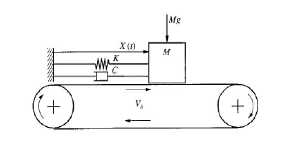 | Figure 2. DOF model |
If µ is assumed to decrease linearly with sliding velocity, the equations of motion of the pad will be as indicated in the below equations: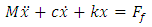 | (2.1) |
 | (2.2) |
 | (2.3) |
 | (2.4) |
The dampingterm  would be negative, representing instability, if
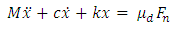
  and the amplitude of the pad vibration would then increase. The negative µ-speed dependence is known to aggravate noise caused by other mechanisms at low speeds. The self-excited, stick-slip oscillation characteristics can be examined by the following equation.
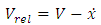 | (2.5) |
 | (2.6) |
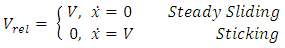
Coulomb’s friction law characterizes the differing friction coefficients for varying relative sliding velocities as shown in Figure 3.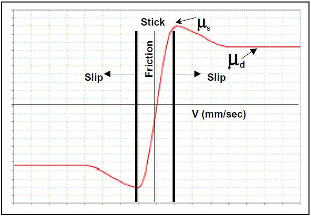 | Figure 3. Coulomb Friction Curve |
At the start of the movement, the mass “M” accelerates due to the friction force to the belt velocity,  . The mass “M” adheres to the conveyor belt, the degree of freedom of the one-degree-of-freedom vibrator is thus force coupled to the moving belt. With the progressive deflection of the spring, the spring force rises until the maximum adhesion force is reached. When exceeding the adhesion force limit set by the adhesion coefficient, the mass slips on the moving belt. Upon transition of the system from adhesion to slip, the degree of freedom of the one degree-of-freedom vibrator ceases to be force coupled. The slipping process is terminated when the mass again reaches the belt velocity. When the damping “c” is greater than the critical damping, the belt velocity is no longer achieved and the movement enters into a damped harmonic vibration.
3. Modeling and Simulation
A simple spring-mass system is sufficient to understand and simulate the friction induced vibrations in the system. The complex brake system can be reduced and idealised as the simple 1 degree of freedom model where the brake pad is represented by a mass resting on the conveyor belt which represents the brake disc. The mass is held in place using the spring of suitable stiffness. The values of the mass and spring are appropriately chosen such that they are realistic and physical.For simulation, transient non-linear implicit solver is necessary to capture the non-linearity and dynamic instabilities in the system. In this study, LMS Virtual. Lab software tool provides the necessary platform to carry out the simulation. BDF type of solver is used in the software to solve the equations of motion. The input parameters are selectively chosen based on the literature and the objectives defined.
3.1. Friction Model
Since, friction-induced vibration can be accomplished only when force-oscillations are accompanied by motion oscillations along the direction of the force oscillations with a suitable relative phase, the simplest and most well-known way to generate such a situation is when the coefficient of sliding friction decreases with relative sliding velocity. Thus an appropriate friction law that encompasses the above criteria must be chosen. The most prominent friction model in the literature for a dynamic system is given by simple velocity dependence, often assumed to be monotonically weakening with increasing velocity such as the Coulomb friction law where the coefficient of static friction is higher than the dynamic coefficient of friction and the friction appears to decrease non-linearly over a function of velocity. In general, a monotonic sliding friction coefficient can be described by a functional relationship to relative velocity and three independent friction parameters.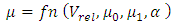 | (3.1) |
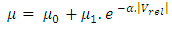 | (3.2) |
From the above figure it can be seen that, static friction coefficient (µ0) is larger than dynamic friction coefficient (µ1) and µ decreases exponentially over relative velocity between pad (mass) and disc (belt). This forms the basis for the most critical parameter in this study, which is, friction parameter. The exponential law defined above covers the basic necessity for inducing and observing the stick-slip phenomenon as explained with help of the Coulomb friction law. In LMS Virtual. Lab, it is imperative that contact friction be defined with the help of the exponential friction curve, either by directly inputting the values of µ vs velocity or defined with a formula definition similar to the one given in the above equation 3.2.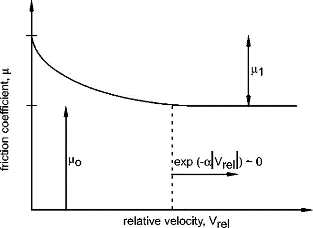 | Figure 4. Velocity dependent friction curve with μ0 and μ1 |
3.2. Contacts in MBS
Contact between objects is an important aspect in multi-body dynamics. It is a discontinuous, non-linear phenomenon and therefore requires iterative calculations. In contact mechanics there are multiple models for predicting contact forces and geometrical deformations [6]. Contact theory chosen for this study is the Hertzian contact theory. Contact is defined between the pad and disc which also includes the complex friction law. The contact parameters are so chosen such that the contact is physical and close to the realistic behaviour. The Hertzian contact is defined with Coefficient of Restitution of 1 which implies that the contacts are elastic in nature and allows negligible penetration.
4. Results and Discussion
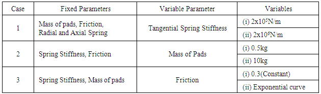
In this study, the minimal model is utilized to study the phenomenon of Slip-Stick occurring in a disc brake. The slip-stick phenomenon, as described in the above chapter, is a friction induced vibration and occurs mainly due to the non-linear and velocity dependent friction parameter.Investigation of slip-stick process is carried out on a model that includes only the brake disc and the brake pad. All the other components such as the caliper, carrier and the suspension components are not included. The brake disc is represented by a rotating belt with constant velocity at a velocity less than 1.5 km/hr as is the standard in all the literatures. The pad is held in place through a spring and damper system which allows only 1 degree of freedom as shown in Figure 2. Contact is defined between the pad and disc using point to surface contact.The stick-slip phenomenon is investigated in depth by studying the effect of the critical parameters on the minimal (reduced) model. The parameters that are considered for this investigation are mass of the pad (M), spring stiffness (k), friction-speed characteristic (μ-V). These parameters are divided into three subcases and are varied keeping others fixed. Initially, the mass and friction values are kept constant and spring stiffness value is varied and the results are plotted. Next, a suitable spring stiffness value is chosen with pre-defined friction parameter and the mass of the pad assembly is varied and its effects are studied. Finally, both mass and spring stiffness are kept constant and only the friction parameter is varied as shown in table 1.Table 1. Stick-slip study cases
 |
| |
|
The initial spring stiffness value is chosen such that it matches closely with the structural stiffness of the caliper assembly of a modern car. To check the sensitivity of the parameter, the value is multiplied by a factor of 10 and is then analysed. Similarly, for the second case of mass sensitivity, the initial value closely resembles the actual mass of the brake pad and is later altered to arbitrary value for sensitivity analysis. The friction parameter is the most important parameter. Constant value of coefficient of friction is used as a control check i.e. whether the oscillations obtained are actually friction induced or are they some random vibrations of the system.The results are obtained from the post-processor tool in the software extracted using markers on the body of the pad.To study the effect of spring stiffness on the stick-slip effect and by that understand the cause of brake groan, the spring stiffness (Case 1) values are changed keeping other input same. The result of this study is shown in figure 5.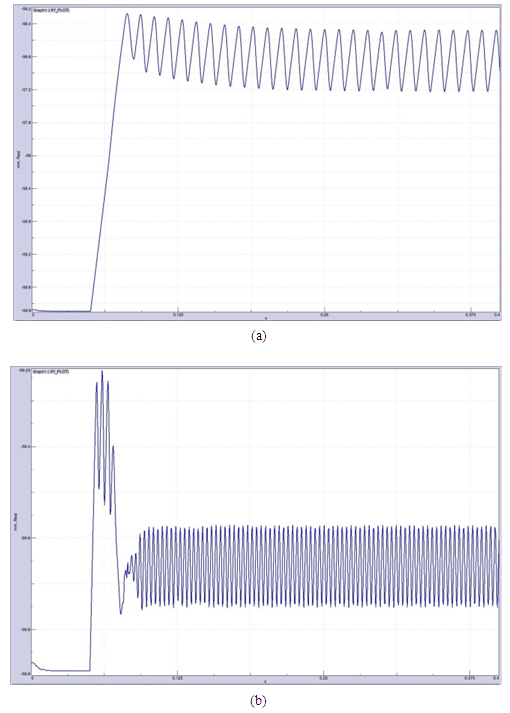 | Figure 5. Displacement vs Time plot of the pad for two different spring values  |
Now to understand the behavior of mass variation, two simulations are carried out with different mass values to study the stick-slip behavior (Case 2). The results of these simulations are given in figure 6.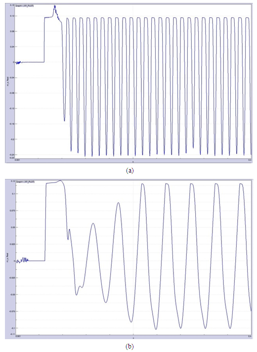 | Figure 6. Displacement vs Time plot of the pad for two different mass values (a) 0.5 kg (b) 10 kg |
Finally, the importance of friction parameter to observe and simulate stick-slip phenomenon is studied (Case 3). Here friction is varied from a constant value to a velocity dependent function and its results are given below: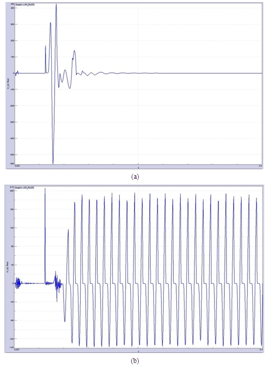 | Figure 7. Acceleration vs Time plot of the pad for two different friction values (a) Constant friction (b) Exponential friction |
5. Conclusions
From the results obtained for the minimal model stick-slip analysis, the following observations can be made:The motion of the pads in the tangential direction indicate that they are friction induced i.e. stick-slip due to the velocity dependent friction. The initial motion when the disc just starts to rotate, creep groan is observed. The creep groan provides the initial energy to the system and induces the next stick-slip cycle. Similar observations are made in other studies as well such as Mohammed et al [7].The parameters of the system such as, mass of pad, spring stiffness and friction control the stick-slip phenomenon. As the spring stiffness is increased, the net force becomes larger than the frictional force and thus the sticking period is reduced. This leads to shorter stick-slip limit cycles and thus frequency changes. When the mass of the pads in increased, the overall inertia of the body increases and thus it absorbs more energy out of the system leading to longer sticking period. From the friction parameter check, it can be clearly observed that the system does not show any stick-slip or friction induced vibrations when the friction value does not vary with relative speed. Thus an exponentially decreasing friction value with increasing relative velocity is necessary criteria to induce self-excited vibrations.Thus, the stick-slip phenomenon is simulated and analyzed using the multi-body simulation on a simple minimal model using LMS Virtual Lab software and a better understanding of the stick-slip phenomenon is obtained and the underlying parameters that affect it are studied.
ACKNOWLEDGEMENTS
I’d like to acknowledge the entire staff and personnel of the mechanical department of BMS College of Engineering for supporting me through my Master’s program.I’m grateful to have a strong and ever-supporting family and friends who have been an integral part of the project.
References
| [1] | A. Day, Braking of Road Vehicles, United States: Elsevier Inc, 2014. |
| [2] | A. M. Rabia, N. Ghazaly, M. Salem and A. Abd-El-Tawwab, "Experimental Studies of Automotive Disc Brake Noise and Vibration: A Review," International Journal of Modern Engineering Research, vol. 3, no. 1, pp. 199-203, 2013. |
| [3] | N. P. Hoffmann and L. Gaul, "Friction Induced Vibrations of Brakes: Research Fields and Activities," SAE Technical Paper Series, pp. 01-2579, 2008. |
| [4] | H. Ouyang, W. Nack, Y. Yuan and F. Chen, "Numerical Analysis of Automotive disc brake squeal," International Journal Vehicle Noise and Vibration, vol. 1, no. 3, pp. 207-231, 2005. |
| [5] | J. Brecht and K. Schiffner, "Influence of Friction Law on Brake Creep-Groan," SAE Technical Paper Series, pp. 01-3138, 2001. |
| [6] | J. Giesbers, "Contact Mechanics in MSC ADAMS," University of Twente, Netherlands, 2012. |
| [7] | A. A. Y. Mohammed and I. Rahim, "Investigate Stick-Slip Intervals with One Equation of Motion and Analyse the Effect Of The Friction Noise," International Journal Of Scientific & Technology Research, pp. 96-117, 2013. |
 Abstract
 Reference
 Full-Text PDF
 Full-text HTML