-
Paper Information
- Next Paper
- Previous Paper
- Paper Submission
-
Journal Information
- About This Journal
- Editorial Board
- Current Issue
- Archive
- Author Guidelines
- Contact Us
Journal of Mechanical Engineering and Automation
p-ISSN: 2163-2405 e-ISSN: 2163-2413
2015; 5(3B): 84-88
doi:10.5923/c.jmea.201502.17
A Study on Vibration Characteristics of Engine Oil Based Magnetorheological Fluid Sandwich Beam
 Abstract
 Reference
 Full-Text PDF
 Full-text HTML
Chethan Arjun Walikar 1, Shreedhar Kolekar 2, Hanumantharaya R. 1, K. Raju 2
1Department of Mechanical Engineering, Sahyadri College of Engineering and Management, Mangaluru
2Department of Mechanical Engineering, St Joseph Engineering College, Mangaluru
Correspondence to: Shreedhar Kolekar , Department of Mechanical Engineering, St Joseph Engineering College, Mangaluru.
| Email: |  |
Copyright © 2015 Scientific & Academic Publishing. All Rights Reserved.
Magnetorheological fluids belong to a group of smart materials. The key feature of Magnetorheological fluids is that their rheological properties will change on the application of magnetic/electric field. The ability to change from liquid to semi solid can be used to provide a good damping effect. Using this concept a cantilever beam structure has been fabricated. It consists of three layers of which the top and bottom layers are of aluminium plates and between the plates an MRFluid has been sandwiched. This experimental study investigates the controllability of vibration characteristics such as natural frequency, amplitude of vibration, damping factor and demonstrates the vibration suppression capabilities of MR fluids in structural elements.
Keywords: Vibration analysis, MRFluid, Sandwich beam, Natural frequency, Damping factor
Cite this paper: Chethan Arjun Walikar , Shreedhar Kolekar , Hanumantharaya R. , K. Raju , A Study on Vibration Characteristics of Engine Oil Based Magnetorheological Fluid Sandwich Beam, Journal of Mechanical Engineering and Automation, Vol. 5 No. 3B, 2015, pp. 84-88. doi: 10.5923/c.jmea.201502.17.
Article Outline
1. Introduction
- Vibration is a continuous cyclic motion of a structure or a component; the vibrations degrade the performance of the system and sometimes damage the entire system. Generally, engineers try to avoid vibrations, because these vibrations have a number of unpleasant effects i.e. cyclic motion implies cyclic forces, which are very damaging to materials, even modest levels of vibration can cause extreme discomfort. Structural vibrations, vehicle suspension systems, precision machinery etc are the examples where vibration suppression is an issue. The structural vibrations can be reduced by adding damping in specified locations and also by adding damping in some additional devices such as vibration isolator or a vibration absorber. The constrained layer damping treatment is more effective because viscoelastic materials dissipate energy mainly by shear deformation and the constraining layer enhance the magnitude of shear deformation. Sandwich beam, plate, and shell structures, as reviewed by Sun and Yu [1] have been developed for practical applications in damping augmentation. Kerwin [2] presented the first analysis of the simply supported sandwich beam using a complex modulus to represent the viscoelastic core. His model predicted attenuation of a travelling wave for a simply supported or infinitely long beam. Di Taranto [3] extended Kerwin’s work by developing a sixth order differential equation of motion in terms of longitudinal displacement. Mead and Markus [4] derived the same order differential equation of motion in terms of transverse motion of sandwich beam and presented the wave propagation solution. Both of them used Kerwin’s basic assumptions, in which the viscoelastic core has a complex modulus and the energy is dissipated by the shear deformation in the viscoelastic core, and both extended Kerwin’s work by allowing for more general boundary conditions. Since 1950s, there have been many papers published on the theory and application of constrained layer damping. Many researchers used Kerwin’s assumptions, and investigated the validity of assumptions and damping or loss factor predictions. Closed-form solution methods were typically used because finite element techniques were not readily available for this class of problems. Nakra [5] and Mead [6] have reviewed on the same and they discussed the differences and similarities between the theories. The above theories laid the foundation for the analysis of sandwich beams with constrained layer damping treatments. Active vibration control systems are used in vibration suspension of structures to adjust to the changes in the structural properties and excitation. Use of active vibration control device proves to be expensive. On the other hand use of semi active vibration devices are found in different applications such as structures and automotive suspension. MR fluids can provide rapid changes in stiffness and damping properties with application of magnetic field [7]. Electro rheological fluids have low yield strength compared to that of MR fluids. ER fluids have the limitations such as high voltage and sensitive to impurities [8]. MR fluids produce yield stress in the order of 2-5 KPa range in the absence of magnetic field which rapidly increases to 75 KPa on the application of magnetic field in the order of 2500 Tesla [9]. Properties of MR fluid dampers have been widely characterized experimentally and analytically for vibration suspension system and structures. Sandwich structures that are fabricated are implemented as distributed vibration absorbers to absorb unwanted vibrations.Ross and his co-workers established the concept of using complex elastic moduli for the analysis of laminated sandwich beam [10]. An experimental study investigates the controllability of vibration characteristics of magnetorheological cantilever sandwich beams. These adaptive structures are produced by embedding an MR fluid core between two elastic layers. The structural behavior of the MR beams can be varied by applying an external magnetic field to activate the MR fluid. The stiffness and damping structural characteristics are controlled, demonstrating vibration suppression capabilities of MR fluids as structural elements by W H Li et al [11]. The complex modes can only exist when the beam is externally excited by specific “damped normal loadings” which are also complex and which are proportional to the local transverse inertia loading on the beam.Lara-Prieto et al [21] found that the structural behaviour of the MR beams can be varied by applying an external magnetic field to activate the MR fluid. The stiffness and damping structural characteristics are controlled, demonstrating vibration suppression capabilities of MR fluids as structural elements. So far there is no complete research work on MR adaptive space structures.In the present work MR fluid sandwich beam is fabricated and studied under cantilever condition. This is the simple structure to implement MR fluid technique. This cantilever structure can effectively represent simple model for various transport vehicle structures like aircraft wing, helicopter blade etc. The beam consists of MR fluid sandwiched between two aluminium plates. The MR fluid whose carrier oil is engine oil with suspended nickel particles in it. The main objective of this study is to provide vibration suppression capability in the form of MRFluid filled cantilever sandwich beam whose natural frequency, amplitude of vibration and damping factor can be easily controlled by means of electromagnetic field.
2. Fabrication of Magnetorheological Fluid Sandwich Beam
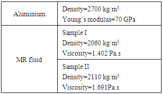
2.1. Properties of Aluminium and MR Fluid
- MR fluid sandwich fabricated consists of two rectangular Aluminium plates. The MR fluid prepared is filled between two plates and Silicone rubber is used at the edges to prevent leakage of the MR fluid.
2.2. Preparation of MR Fluid
- MR Fluid is prepared in the laboratory using Engine oil as carrier oil, Nickel as magnetic particles and oleic acid as a surfactant. Two samples are prepared in the laboratory on the basis of weight.Sample I: Carrier oil: Engine oil -65% Magnetic Particles: Nickel-35%; Additives: Oleic acid- 15% Sample II: Carrier oil: Engine oil – 55% Magnetic particles: Nickel – 45%; Additives: oleic acid – 15%
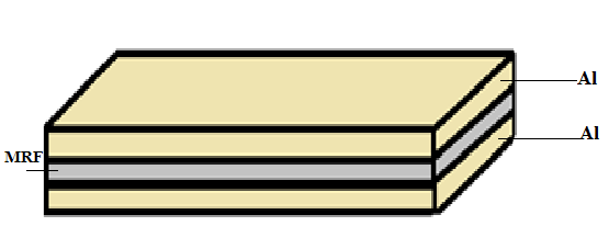 | Figure 1. MR Fluid sandwich beam |
|
|
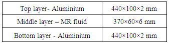
2.3. Experimental Setup
 | Figure 2. Experimental setup |
2.4. Experimental Procedure
- 1. Pour MR Fluid in to the cavity of the beam and close the top layer and screw the nuts of beam tightly such that no outflow of beam takes place.2. Clamp the beam to one end of the frame and attach the accelerometer.3. Magnetic field is applied to the beam by varying current intensity. Initially set the magnetic field to 0.05Tesla4. Note down the frequency and amplitude values. Repeat the experiment for different magnetic fields say 0.1T, 0.15T, 0.2T, 0.25T and record the frequency and amplitude values for each case.
3. Experimental Results
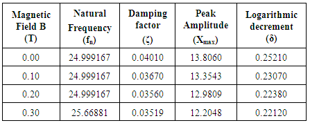
3.1. Results for sample I (Engine oil -65%, Nickel- 35%, oleic acid-15%)
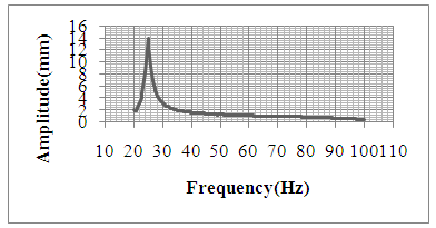
- 1) Beam filled with MR fluid and No magnetic field applied (B=0)In this case beam was filled with MR fluid and no magnetic field was applied to the beam. Then beam was subjected to excitation and change in amplitude noted for all the frequencies. From the obtained values a graph was plotted amplitude versus frequency and natural frequency was determined (Figure 3).
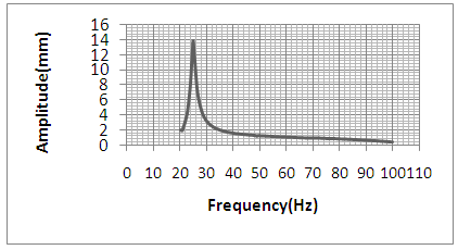 | Figure 3. Amplitude v/s Frequency plot for 0Tesla |
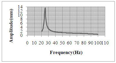
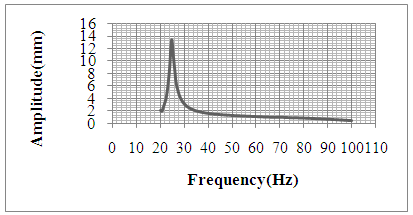 | Figure 4. Amplitude v/s Frequency plot for 0.1Tesla |
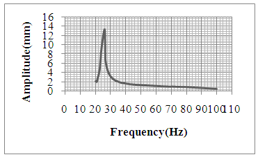
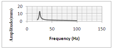 | Figure 5. Amplitude V/s Frequency plot for 0.2Tesla |
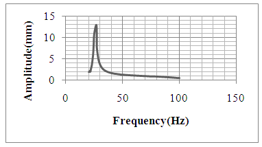
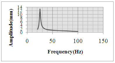 | Figure 6. Amplitude v/s Frequency plot for 0.3 Tesla |
3.2. Results for Sample II (Engine oil-55%, Nickel- 45%, Oleic acid-15%)
- 1) Beam filled with MR fluid and No magnetic field applied (B=0)In this case beam was filled with MR fluid and no magnetic field was applied to the beam. Then beam was subjected to excitation and change in amplitude noted for all the frequencies. From the obtained values a graph was plotted amplitude versus frequency and natural frequency was determined.
 | Figure 7. Amplitude V/s Frequency plot for 0Tesla |
 | Figure 8. Amplitude v/s Frequency plot for 0.1 Tesla |
 | Figure 9. Amplitude v/s Frequency plot for 0.2 Tesla |
 | Figure 10. Amplitude V/s Frequency plot for 0.3Tesla |
|
|
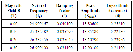
4. Conclusions
- The influence of MR fluid increases with increase in magnetic field. The MR fluid changes from liquid to semi solid state on the application of magnetic field. This causes increase in the stiffness of the beam and hence there will be a shift in natural frequency of the beam. It was found that the peak amplitude of vibration decreases as the magnetic field intensity increases. This indicates that presence MR fluid can be used to reduce vibration in system. Damping factor changes by 14% which indicates that presence of MR fluid under the influence of magnetic field can provide good damping effect. From the results of two different samples one can say that the fluid with more percentage of magnetic particles can provide better performance.
ACKNOWLEDGEMENTS
- Our sincere thanks to Dr. K. V. Gangadharan, Professor, Department of Mechanical Engineering, NITK, Surathkal, for providing the facilities to conduct the Experimental Tests in the Vibration Lab.