Sudeep Kelaginamane , Sridhar D. R.
Department of Mechanical Engg, MITE, Moodabidri, India
Correspondence to: Sudeep Kelaginamane , Department of Mechanical Engg, MITE, Moodabidri, India.
| Email: |  |
Copyright © 2015 Scientific & Academic Publishing. All Rights Reserved.
Abstract
The work here describes about the design and fabrication of automatic sheet metal punching machine controlled by Programmable Logic Controller (PLC). It also describes the working principle and the hardware structure of the system. By automating the punching system one can have greater control over the whole process. This system can replace existing manual feed and operated punching machines. By interfacing PLC, it is possible to get good results in the form of increased safety of the worker, reduced manufacturing lead time and reduced angular misalignment.
Keywords:
Punching Machine, PLC, Pneumatics, DCV, Ladder logic programming
Cite this paper: Sudeep Kelaginamane , Sridhar D. R. , PLC Based Pneumatic Punching Machine, Journal of Mechanical Engineering and Automation, Vol. 5 No. 3B, 2015, pp. 76-80. doi: 10.5923/c.jmea.201502.15.
1. Introduction
The modern world is more practical and cost-conscious, so the punching process for sheet-metal has to be done in an accurate and more precise way with the relative economy of operation, easier implementation for mass-production, as well as greater control on the technical parameters. In most of the sheet metal operations punching or pressing operation is the main or initial operation in the process sequence. Automating this operation results in reduced lead time and also can reduce human effort. Automation is a process in which technology concerned with application of mechanical, electronic and computer-based systems to operate and control production. The reason for automating this process may be to reduce manufacturing lead time, to increase labour productivity or to improve the worker safety, etc. [1].
1.1. Punching Process
In punching process the tool is designed to punch blank of sheet by applying mechanical force. The automated punching process are helpful for mass production and they represent the fastest and more efficient way to form a metal into a finished punched product. Manual or conventional methods of punching have following disadvantages• Angular misalignment of the sheet• It requires higher material handling time and manufacturing lead times• Reduced safety of the worker.
1.2. Programmable Logic Controllers
A Programmable logic controller (PLC) is a digital electronics device that uses a programmable memory to store instructions and to implement specific functions such as logic, timing, counting and arithmetic operations to control machines and processes. [8]It can be said as an industrial computer that has a central processor unit, memory, input/output interface and a programming device. The central processing unit is the intelligence of the controller. These central processing units accepts data, status information from various sensing devices like limit switches, proximity switches, executes the user control program store in the memory and gives appropriate output commands to devices like solenoid valves, switches etc. In this paper the automation is achieved by interfacing the sensors and PLC system with the conventional punching process.
1.3. Pneumatic Systems
Pneumatic systems work with the help of compressed air. Certain characteristics of compressed air have made this medium quite suitable for use in modern manufacturing and production plants. Wide availability of air, compressibility of air, fire proof characteristic of the medium, high degree of controllability, comparatively cheaper in cost are some of the features of pneumatic systems. [9]Air which is available naturally is invisible, colourless, odourless and tasteless. Main constituents of air by volume are 78%nitrogen, 21%oxygen, %carbon dioxide and other gasses including some amount of water vapours. Air which is a mixture of various chemical elements follows the gas law, like any other perfect or ideal gas. A compressor will compress the naturally available air to required range, which then can be used in the pneumatic systems.
2. Working Methodology
Mainly three components are used in this system. They are Loading Cylinder, Unloading Cylinder, and Punching Cylinder. All these cylinders are operated in a sequence in order to perform the required operation. The sheet metal that has to be punched is stacked in a container which has an outlet which allows only one sheet metal at a time. Limit switches and proximity sensors are placed to know the positions of the cylinders, weather in extended or retracted conditions. According to the inputs from the sensors and the program written, the loading cylinder will load the work piece into the holder, then the punching cylinder will punch the work piece and finally the unloading cylinder will unload the work piece from the work piece holder.
3. Design and Modeling of the System
3.1. Modelling
As per the requirements, for punching an aluminium sheet with a thickness of 0.7 mm, a punching cylinder of 50mm diameter with stroke length of 200mm, the loading and unloading cylinder with diameters of 16mm and stroke length of 100mm are chosen. And C channel steel is used for the frames (fig 1-3).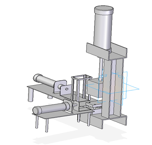 | Figure 1. Design of the model |
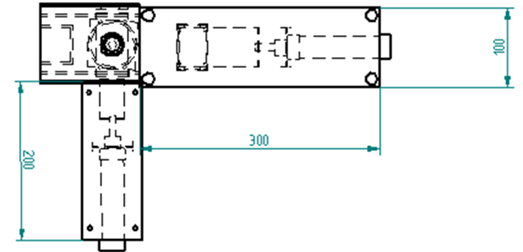 | Figure 2. Top view dimensions in mm |
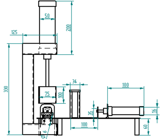 | Figure 3. Side view dimensions in mm |
The die is made up of cast iron with 6.1mm diameter hole. The die has a punch head attached to it with supporting spring for the easy damping, the punch head is made of en353 material with hardening to assure proper punching (Fig 4). 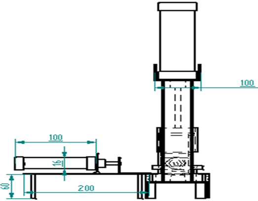 | Figure 4. Right side view dimensions in mm |
An L-shaped aluminium structure (Fig.6) with 0.7mm thickness is attached to both the pistons of loading and unloading cylinders for easy loading and unloading of the work piece.
3.2. Force / Load Calculations
To know the diameter of the punching cylinder, the force required for punching must be first calculated. The punching force can be calculated by using the formula, | (1) |
Where P is the punching forcel is the punching profile length[mm]( where D=diameter of punched hole)t is the material thickness [mm]
 material shearing resistance [kgf/mm2].Here the value of punching profile length is 15mm, material thickness is 0.7mm, and material shearing resistance is 7Kgf/mm2.Therefore
 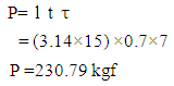 | (1) |
To calculate the diameter of the cylinder, the formula of force is used, | (2) |
Where Fp is the punching forceP is pressure [N/m2]Ap is the area of the cylinder [m2]( where dp is the diameter of cylinder).Substituting the value of Ap in equation (2),
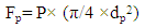 | (3) |
By rearranging the equation (3) the equation for diameter of piston will be,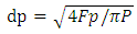 | (4) |
Here the punching force is 2307.9N and Pressure is 10×105N/m2.Therefore 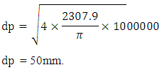 To calculate the force applied by the dead weight that is mounted on the punching piston head,
 | (5) |
Here weight is 2.5 kg, gravitational force is 9.8m/s2 and height is 0.2m.Therefore P.E = 2.5 × 9.8 × 0.2P.E = 4.9 joulesThe force exerted by the pneumatic system is added with the force exerted by the dead weight to get the total punching force.Therefore 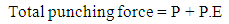 | (6) |
Where P is punching forceP.E is potential energy.Here the value of punching force is 230.79Kgf and the value of potential energy is 4.9 joules.Then the equation (6) will be Total punching force = 230.79 + 0.4996  = 231.2896 kgf
3.3. Dimensions
The dimensions of the parts used in the system are as shown in the below figures.Apart from all these design specifications a dead weight of 2.5kg is added to the head of punching cylinder to increase the efficiency of punching. Limit switches and proximity sensors are used to know the position of the cylinders whether in the extended or retracted condition and one proximity sensor in extra for detecting the presence of the sheet metals in the rack.
4. Design of Pneumatic Circuit
The model consists of three 5/2 Direction Control Valves (DCV) which are solenoid actuated and spring return. This DCV has two positions, in the first position the DCV allows air to move in one direction and in the second position the DCV will allow the air to move in the other direction. The switching can be made between the positions by using solenoid. When the solenoid is activated it will change the direction of air path by pulling in or out the spool arrangement. As it’s a spring return DCV the spool will return to the initial condition. This will control the piston extension and retraction as required.Two sensors are used in each of the cylinders to exactly mention whether the piston is in extended or retracted condition. The sensors used may be limit switches or proximity sensors. All these limit switches and proximity sensors are inputs to the PLC system.B1 and B2 are the limit switches used in the loading cylinder, where B1 will represent the retracted condition and B2 the extended condition. It is shown in figure 5.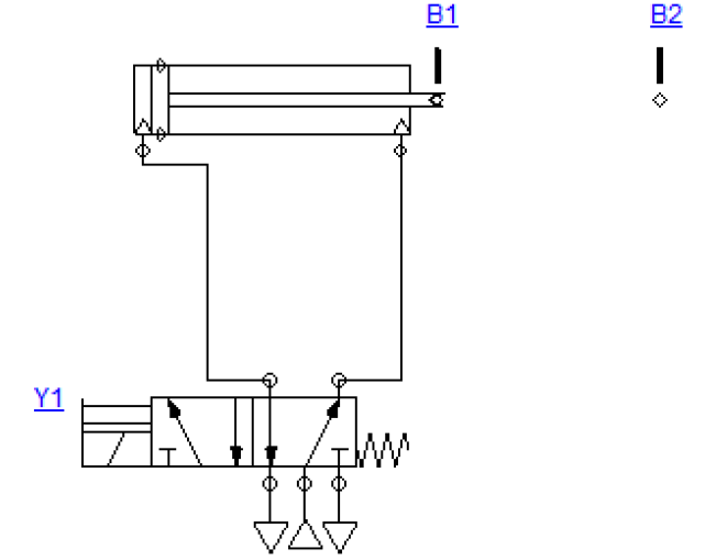 | Figure 5. Loading cylinder |
B3 and B4 are the proximity sensors that are used in the punching cylinder to represent the position, where B3 represents the retracted condition and B4 represents the extended condition. It is shown in figure 6. 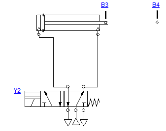 | Figure 6. Punching cylinder |
In the unloading cylinder, B5 and B6 are the limit switches used to represent the retracted and extended conditions respectively. As shown in the figure 7. | Figure 7. Unloading cylinder |
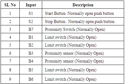
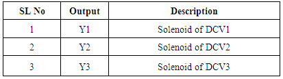
Y1, Y2 and Y3 are the three outputs from the PLC and those are given to the Direction Control Valves (DCV). 5/2 Direction Control Valves which are spring return and solenoid controlled are used here.Table 1. Inputs to the PLC
 |
| |
|
Table 2. Outputs from the PLC
 |
| |
|
4.1. Sequence of Operation
1. When the start button S1 is pressed the intermediate value Hold go high and it will stay high until stop button S2 is pressed, this will happen only when the proximity sensor B7 detects the metal piece on the rack. 2. Initially all the cylinders will be in retracted positions and the limit switches B1, B3 and B6 will be active. The value of Hold and B5 switch will be high which gives an intermediate output K1. When the K1 is high it makes the output Y1 go high, which intern makes the solenoid controlled DCV switch ON. And thus the loading cylinder will extend.3. When loading cylinder is fully extended it will make the limit switch B2 active this makes the intermediate output K2 to go high, which intern shuts down the output Y1. Thus the solenoid activated DCV will deactivate and hence the loading cylinder will retract back.4. As the loading cylinder retracts back, it will activate B1 limit switch which will make the intermediate output K3 go high and intern switches the output Y2 high. Thus the punching cylinder will extend.5. Once the punching cylinder extends it will activate the proximity sensor B4 which intern switches the intermediate value K4 and output Y2 to go low. Thus retracting the punching cylinder.6. The retracted punching cylinder will make the proximity sensor B3 active and switches the intermediate value K5, which makes the output Y2will go high. Thus making the unloading cylinder to extend.The extended position of unloading cylinder will trigger the limit switch B6 and switches the intermediate output K6, thus making the unloading cylinder to retract.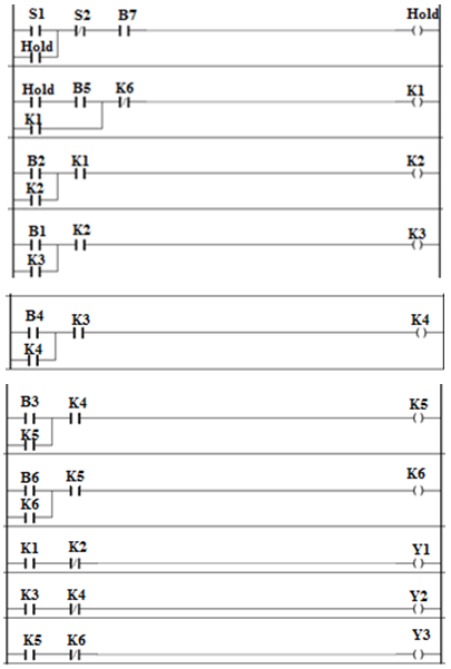 | Figure 8. Ladder logic program |
5. Programming
5.1. Ladder Logic Programming
The programming language used here is ladder logic. It represents a program by a graphical diagram which is based on the circuit diagrams of relay logic hardware. It is used to develop software for programmable logic controllers (PLCs) in industrial control applications. The name is because of programs in this language resemble ladders, with two vertical rails and a series of horizontal rungs in between them.
5.2. Indra Control L20
The Indra Control L20 is a modular and scalable control. It has the combined benefits of a compact small control with a standardized I/O system on the basis of terminal technology. It is a hardware system that can be used for PLC applications. It provides an on-board interfaces, e. g. high-speed inputs and outputs (8 each) and communication interfaces, such as Ethernet, PROFIBUS and RS232. The locally available I/O units can be extended by the Rexroth Inline input/output system, just by simply mounting the components side by side.
6. Conclusions
In this paper design and control method of sheet metal punching machine is explained. By using Programmable Logic Controllers as the controller of the whole system, good and easy control over the system can be achieved. Manufacturing lead time of the system is reduced by developing automatic feeding mechanism, worker safety is increased by reducing the human participation in the process and the problem of angular misalignment of sheets is also reduced.The manually operated system will roughly produce 60 units per hour and 600 units in 10 hours, whereas automated punching machine will produce 420 units in one hour and 4200 units in 10 hours. This is shown in the figure 9.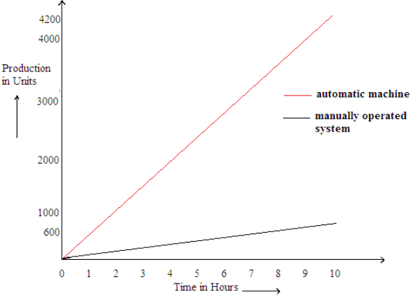 | Figure 9. Automatic versus manual system |
References
| [1] | Arun S, Sree Rajendra and Vijayavithal Bongale, “Automatic Punching Machine: A Low Cost Approach” International Journal of Advanced Mechanical Engineering. ISSN 2250-3234 Volume 4, Number 5 (2014), pp. 509-517. |
| [2] | Qiao Dongkai, Yang Xiangyu, Jia Jinxin, “The Application of PLC to CNC Machine Tools Development” Digital Manufacturing and Automation (ICDMA), 2011 Second International Conference on DOI: 10.1109/ICDMA.2011.299 Publication Year: 2011, Page(s): 1213- 1216 Cited by: Papers (1) IEEE conference publications. |
| [3] | Brecher, C, Lohse, W & Herfs, W Mechatronic development of PLC software with virtual machine tools Control and Automation, 2009. ICCA 2009. IEEE International Conference on DOI: 10.1109/ICCA.2009.5410362 Publication Year: 2009, Page(s): 2392- 2397 IEEE Conference publications. |
| [4] | A.S. Aditya Polapragada and K. Sri Varsha, “Pneumatic Auto Feed Punching and Riveting Machine” International Journal of Engineering Research & Technology (IJERT) ISSN: 2278-0181 Vol. 1 Issue 7, September – 2012. |
| [5] | Dr. Majid A. Oleiwi, Abdul Muhsin M. Al-Timimi & Ammar Abdulhussein, “Design & Simulation of PLC Control and Electro-Hydraulic System for a Punching Machine” Eng. & Tech. Journal, Vol. 27, No.8, 2009. |
| [6] | Vijaylaxmi G. Biradar, Siddharam Patil & R M Lathe, “Automation of Sheet Bending Machine Using Electro Pneumatic Devices” International Journal of Scientific & Engineering Research Volume3, Issue 9, September-2012 ISSN 2229-5518. |
| [7] | P. Tamil Arasu, R. Dhanasekaran, P. Senthil Kumar & N. Srinivasan, “Effect of Hardness and Microstructure on En 353 Steel by Heat Treatment Research Inventy” International Journal Of Engineering And Science” Vol.2, Issue 11 (April 2013), Pp 01-05 Issn(e): 2278-4721, Issn(p):2319-6483. |
| [8] | Pragnya Pradeep, Siddharam Patil & R M Lath, “Automation of Milling Machine Using Electro Pneumatic System” International Journal of Engineering Research and Development e-ISSN: 2278-067X, p-ISSN: 2278-800X, www.ijerd.com Volume 2, Issue 9 (August 2012), PP. 04-094. |
| [9] | A.S. Aditya Polapragada, K. & Sri Varsha, “Pneumatic Auto Feed Punching and Riveting Machine” International Journal of Engineering Research & Technology (IJERT) ISSN: 2278-0181 Vol. 1 Issue 7, September – 2012. |
| [10] | Madhuchandra Mitra & Samarjit Sen Gupta, “Programmable Logic Controller And industrial Automation an Introduction” Penram International Publishing (India) Pvt.Ltd. |
| [11] | S R Majumdar, “Pneumatic Systems Principles and Maintenance” Tata McGraw Hill Education Private Limited, New Delhi. |
 Abstract
 Reference
 Full-Text PDF
 Full-text HTML