Jayanthan M. , Srinivas V.
Bridge Engineering Group, CSIR-Structural Engineering Research Centre (SERC), Taramani, India
Correspondence to: Srinivas V. , Bridge Engineering Group, CSIR-Structural Engineering Research Centre (SERC), Taramani, India.
| Email: |  |
Copyright © 2015 Scientific & Academic Publishing. All Rights Reserved.
Abstract
For the past few decades, finite element modeling has been extensively used as a predictive tool in determining the modal properties of the structures, but the responses obtained from finite element (FE) simulations normally differ from those measured. This is mainly because of the inherent physical uncertainties such as boundary conditions, material properties, mass and stiffness in the FE model. Modal parameter based Finite element modal updating procedure is capable to overcome those inaccuracies in FE model, in order to achieve the realistic FE model. The present paper illustrates how the numerical model can be iteratively updated to closely match with the system response of the physical model. In this study, a flat cantilever steel plate is considered as a test specimen. The test specimen is excited with an impulse hammer to measure the vibration responses so as to obtain the resonant frequencies and mode shapes of the structure at undamaged and damaged conditions. Further, the test specimen is numerically modelled using finite element software which is interfaced with the FE model updating tool. The measured data obtained from undamaged condition of the specimen is used as reference data for updating the simulated finite element model and further calibrated undamaged FE model is updated with the data obtained from damaged conditions. The finite element model updating is carried out by choosing the appropriate parameters based on the sensitivity analysis. Finally, it is found that the updated finite element model shows significant improvement in FEM-Test correlation of the modal parameter.
Keywords:
Vibration testing, Modal analysis, Damage identification, FE model updating, FEMTools
Cite this paper: Jayanthan M. , Srinivas V. , Structural Damage Identification Based on Finite Element Model Updating, Journal of Mechanical Engineering and Automation, Vol. 5 No. 3B, 2015, pp. 59-63. doi: 10.5923/c.jmea.201502.12.
1. Introduction
In the present era, the infrastructure facilities such as construction of highways, bridges and multi-storied buildings are developing rapidly. The main factor for determining the country’s development is based on its infrastructures. These structures often subjected to natural disasters such as earthquake, or vibrations due to man-made operations which indirectly induces damages in the structure. Much attention is needed in identifying the damage in the structure and should be rectified in an effective manner to extent the service life of the structure. In order to solve this issue, the structural health monitoring has received much attention to diagnose the problem related to damages. Vibration-based, non-destructive damage identification techniques have been used as effective tool in SHM to determine the damages in structure by analyzing the changes in dynamic properties such as natural frequencies, mode shapes and modal curvature. The natural frequencies and mode shapes are obtained by performing the vibration test on the structure and with modal analysis software. Several studies have been carried out by researchers Doebling et.al, 1998 [2] and Sohn, et.al, 2003 [3] on vibration-based damage identification. The existence of damage is often characterized by the loss of stiffness in a structure which is indicated by the reduction of young’s modulus in the FE model. Damage identification consists of: (1) detecting the occurrence of damage (2) locating the damage zone (3) determining the severity of damage occurred, Rytter 1993 [1]. Several literatures have been presented by various researchers on vibration based methods like Salawu 1997 [5] studied the damage in the structure based on the changes in the natural frequencies. Pandey et al. 1991 [4] introduced the concept of modal curvature mode shapes for damage localization.Over the past few decades, the advent of modern computer to solve large matrices has led to construction of numerical model. One of those numerical approaches is finite element analysis (FEA) which provides tools that can simulate and predict the response of the test structure. Numerous software packages have commercial FEA codes with advanced modules for tackling complex analysis. In most of the cases, the researchers ensure the correctness of the test data by comparing with the numerical model. But, these comparisons found to be insignificant in some cases, resulting in huge error. The simulated FE model often results in uncertainties which are classified as physical and numerical uncertainty (Dascotte, 2007) [6]. The physical uncertainties are namely the boundary conditions, joint stiffness, and material properties (modulus of elasticity, yield stress etc. Numerical uncertainties are due to lack of data of the physical process and lack of system knowledge, mathematical modeling uncertainty, discretization error uncertainties (element type, mesh density and dimension of the model) and human error (program logic error, mistake in data inputs etc.) (Friswell and Mottershead 1995) [7]. Uncertainties may also occur due to variation in physical parameters such as manufacturing tolerances or in-service operation conditions (FEMTools 2003a [10], Ewins 2000 [8]). In order to overcome those inaccuracies, parameter based model updating procedure has received much attention in resolving those problems. In this study, a flat steel plate is considered as a test specimen. Initially, the undamaged test model was modelled using ANSYS which is interfaced with FEMtools software [11] to obtain the dynamic characteristics of specimen. Then, the experimental modal parameters were determined using ARTeMIS software [9] to find out the natural frequencies and mode shapes of the specimen from undamaged to damaged state. The damage is introduced in the specimen by predefined cuts at different locations along the width of the plate. Further, the finite element model is correlated with the damaged measured data and followed by model updating procedure for identifying the damage made in the test specimen.
2. Description of Test Structure
A flat steel plate is considered as a test specimen with the overall dimension of 700 mm x 50mm x 6mm. The specimen is clamped at one end using C-Clamp which acts as fixed end. The instrumentation is carried out using 7 uni-axial accelerometers fixed on the specimen at equal intervals. Impact hammer excitation is performed at different locations to get the desired response of the specimen. The instruments used in the study are the impact hammer with sensitivity of 2.23 mV/g and PCB accelerometers with the sensitivity of 1000 mV/g. The modal response of the specimen is obtained by analyzing the vibration signal using signal analysis tools. Post processing is carried out using frequency domain decomposition (FDD) technique of ARTeMIS, modal analysis software. Through this, the dynamics characteristics of the specimen such as natural frequencies and mode shapes are obtained for undamaged and damaged model. Figure 1 and 2 shows the plan view of undamaged model and experimental arrangement respectively.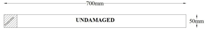 | Figure 1. Plan view of undamaged test specimen |
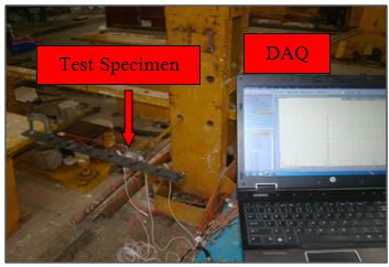 | Figure 2. Experimental setup |
3. Description of Damages in the Test Specimen
To simulate the damage in the system, a hack saw cutting tool is used to cut the plate perpendicular to the axial length of the plate with blade thickness of 2mm. This damage has made to resemble the cracks resulting from fatigue in metallic elements. The plate is damaged at multiple locations by cutting along the width at distances of 100mm, 250mm and 500mm from one end of the plate. Figure 3 & Figure 4 shows the plan view of damaged model and the real case damaged zones respectively.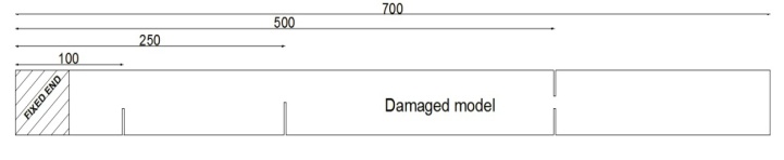 | Figure 3. Plan view of damaged model (All the dimensions are in mm) |
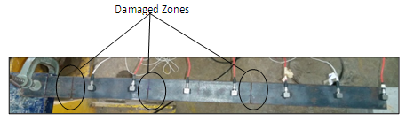 | Figure 4. Real case damage zones |
4. Finite Element Modelling
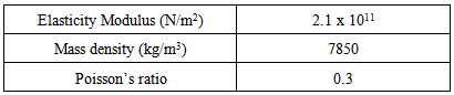
The initial FE model of steel plate is modeled using ANSYS and SOLID 45 element which is defined as eight nodes having three degrees of freedom at each node: translations in the nodal x, y, and z directions. The plate is considered as fully fixed at one end. The model is divided into number of small elements with a mesh size of 5mm. The steel properties include elastic modulus, density and poisson’s ratio as given in the Table 1 and initial FE model is shown in Figure 5.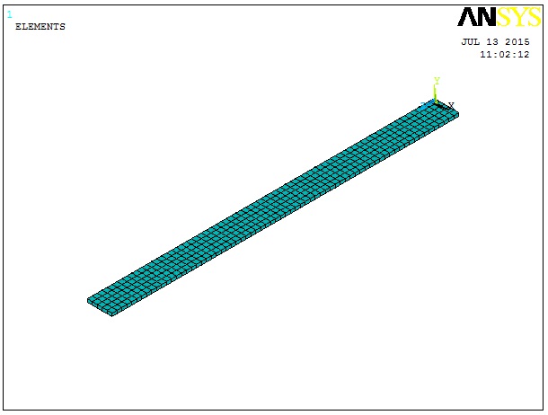 | Figure 5. Initial finite element model |
Table 1. Material Properties of Steel plate
 |
| |
|
5. Model Updating
Model updating is defined as the process of quantifying the difference between finite element analysis and corresponding experimental data and then modifying the numerical value of input parameter in the model to obtain calibrated FE model (Dascotte 2007) [6]. FEMtools software is employed in carrying out the model updating. Model updating process consists of the following steps:Step1: Creating the initial finite element model through commercial FE software.Step2: Interfacing initial finite element model with FEMtools softwareStep3: Importing the experimental data into FEMtoolsStep4: Comparing the experimental and numerically obtained natural frequencies and mode shapesStep5: Defining the convergence criteria for the natural frequencies and mode shapesStep6: Selecting parameters for model updating Step7: Performing sensitivity analysis for selected parameterStep8: Model updating using automated or manual iterative procedure until the convergence criteria is fulfilled.
6. Updating Procedure
6.1. FE Model Tuning for Damage Identification
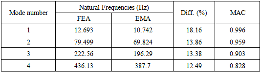
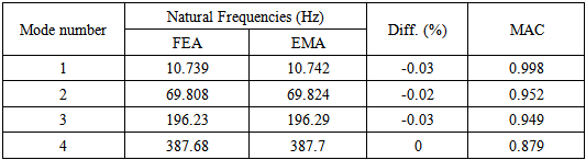
For identification of damage in the plate, initial FE model should be tuned to remove various uncertainties. First, initial finite element model is interfaced with FEMtools software and modal analysis performed using FEMtools solver. Then, the undamaged measured data of the test structure is utilised as reference data to calibrate the initial finite element model. This is called as Model Calibration. Further, the damage identification is made on the calibrated finite element model with damaged measured data as a benchmark. The calibration of finite element model consists of following steps:Step1: Creating initial finite element modelStep2: Calibrating the initial finite element model with the undamaged experimental dataStep3: Calibrated finite element model is utilised for correlating further damage case.Modal parameters identified for undamaged test specimen by numerical and experimental before updating is given in Table 2 and the corresponding mode shapes are shown in Figure 6. It is observed that the maximum difference of frequency error is found to be 18%, while Model Assurance Criteria (MAC) value shows good correlation. To decrease the error in frequency, the initial FE model is calibrated by considering the elasticity modulus of each element as variable parameter. After performing iterative solution, the initial finite element model is calibrated and the natural frequencies obtained after updating is given in Table 3. It is clear that good correlation is achieved between the experimental and calibrated numerical natural frequencies and slight variation of MAC values also noted. | Figure 6. First four mode shapes of undamaged steel plate |
Table 2. Natural Frequencies of initial FE model and Experimental values of undamaged steel plate before updating
 |
| |
|
Table 3. Natural Frequencies of initial FE model and Experimental values of undamaged steel plate after updating
 |
| |
|
6.2. Damage Identification
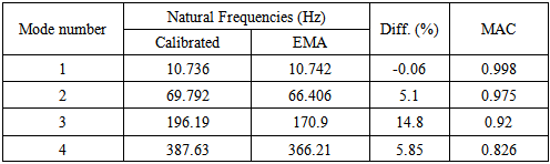
The calibrated initial finite element model which depicts the undamaged test model is used further for correlation with damaged test data in localizing the damage. After inducing the damage to the test model, impact excitation is applied to obtain the dynamic response. The easiest way to identify the damage in the structure is to compare the natural frequencies and mode shapes of the calibrated finite element model with the damaged results. The identified natural frequencies of calibrated model and damaged results with MAC values before updating is given in Table 4 and the corresponding mode shapes for damaged model are shown in Figure 7.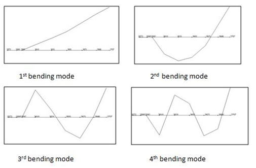 | Figure 7. First four mode shapes of damaged steel plate |
Table 4. Natural Frequencies of calibrated FEmodel and Experimental values of damaged steel plate before updating
 |
| |
|
From Table 4, it can be clearly seen that the existence of damage does not really affect the fundamental modes. There is also slight variation of frequencies seen in second and fourth mode. However, deviations of the natural frequencies for the third modes are clearly noticeable (with almost 15%). The damage in the structure is observed by the change in young’s modulus which indicates the loss of stiffness at the crack location. So, in model updating process elastic modulus is chosen as the updating parameter. The model updating is carried out with in the FEMtools software. The criteria for convergence are set as EPS1 to 0.1, EPS2 to 0.01 and iteration fulfilled the convergence criteria at sixth iteration. At the end of these, there is overall change of elastic modulus in the whole model and it is given as contour plot in Figure 8. 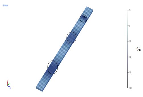 | Figure 8. The change in young’s modulus in the steel plate after updating the calibrated finite element model with the obtained damaged data |
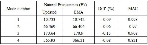
Table 5 gives the natural frequencies of FE model and damaged experimental values after updating. It is observed that the difference between the natural frequencies reduced to less than 1%. From figure 8, the negative scaling explains about the change of young’s modulus in terms of percentage in some specific regions of the finite element model, which indicates the loss of material/stiffness in the particular location. Also, from figure 8 noted that the maximum elastic modulus change is occurred at a distance around 100mm, 250mm and 500mm from one end of the plate which is highlighted by circles. Those reductions in the updated FE model exactly points out the zones where damage created in test specimen.Table 5. Natural Frequencies of updated FEmodel and Experimental values of damaged steel plate after updating
 |
| |
|
7. Conclusions
This paper presented the application of finite element model updating in identifying the damage in structural components using FEMtools software. A random damage case was taken into consideration and the elastic modulus was selected as damage indication parameter. The investigation was performed for first four bending modes. The applied damage detection approach consists of three stages: initial finite element modeling, model calibration and model updating. First, initial finite element model was calibrated using undamaged test model as reference one and updated the model by considering the elastic modulus as variable parameter. This updating produces the calibrated finite element model by minimizing the frequency error between initial finite element model and undamaged test data. Further, for damage identification process, updated finite element model is assumed as validated one since it matches well with the undamaged test data. After inducing multiple damages in the plate, the natural frequencies were found to be decreased considerably and the maximum change was noticed in third mode with almost 15%. To identify the damage location, the calibrated finite element model was updated by choosing elastic modulus as updating parameter. The damage is characterized by reduction in the elastic modulus in the damage region to indicate the loss of material/stiffness. Based on the updating result, the change in elastic modulus across the plate was observed and the region where decrease in elastic modulus is considered as damage location. The damage regions indicated by the finite element model updating matches well with the simulated damage case. Furthermore, the identification procedure also eliminates the uncertainties in numerical model to better match with the experimental data.
ACKNOWLEDGEMENTS
The paper is being published with the kind permission of the Director, CSIR – SERC.
References
| [1] | Rytter, A. “Vibration based inspection of civil engineering structures”, Ph.D. Dissertation, Department of Building Technology and Structural Engineering, Aalborg University, Denmark, 1993. |
| [2] | Doebling, S. W., Farrar, C. R. & Prime, M. B. 1998, A summary review of vibration-based damage identification methods, The Shock and Vibration Digest, 30(2), pp. 99–105. |
| [3] | Sohn, H., Farrar, C. R., Hemez, F. M., Shunk, D. D., Stinemates, D. W. & Nadler, B. R., 2003, A Review of Structural Health Monitoring Literature: 1996–2001, Los Alamos National Laboratory, Report No. LA-13976-MS, Los Alamos, NM. |
| [4] | Pandey, A. K., Biswas, M. & Samman, M. M., 1991, Damage detection from changes in curvature mode shapes, Journal of Sound and Vibration, 145(2), pp. 321–32. |
| [5] | Salawu, O. S. 1997, Detection of structural damage through changes in frequency: a review, Engineering Structures. |
| [6] | Dascotte, E., 2007, “Model updating for structural dynamics: Past, Present and future outlook”, Presented at International Conference on Engineering Dynamics (ICED), April 16-18, Carvoeiro, Algarve, Portugal. |
| [7] | Friswell, M.I. and Mottershead, J.E. 1995, “Finite element updating in structural dynamics”, Kluwer Academic Press, MA. |
| [8] | Ewins, D.J. 2000, “Adjustments or Updating of Models”, Sadhana, 25(3), 235-245. |
| [9] | ARTeMIS Extractor Software. Structural Vibration Solutions, Inc. 1999-2003. Denmark. |
| [10] | FEMtools 2003a, FEMtools Model Updating Theoretical Manual, Version 3.3, Dynamic Design Solutions, Leuven, Belgium. |
| [11] | FEMTools 3.8.1 (64-bit), Dynamic Design Solutions N.V., 1993-2008. Belgium. www.femtools.com |
 Abstract
 Reference
 Full-Text PDF
 Full-text HTML