-
Paper Information
- Next Paper
- Previous Paper
- Paper Submission
-
Journal Information
- About This Journal
- Editorial Board
- Current Issue
- Archive
- Author Guidelines
- Contact Us
Journal of Mechanical Engineering and Automation
p-ISSN: 2163-2405 e-ISSN: 2163-2413
2015; 5(3B): 55-58
doi:10.5923/c.jmea.201502.11
Automation of Generating CAD Models
 Abstract
 Reference
 Full-Text PDF
 Full-text HTML
Siddesh S. , B. S. Suresh
Department of Mechanical Engineering, BMSCE, Bengaluru, India
Correspondence to: Siddesh S. , Department of Mechanical Engineering, BMSCE, Bengaluru, India.
| Email: |  |
Copyright © 2015 Scientific & Academic Publishing. All Rights Reserved.
The main purpose of the work is to shift from manual modelling method to CAD automation process. Instead of repeatedly creating the similar models or changing the parameters in the same models, engineers should be able to create program so that it automatically creates the new CAD models or to generate the further modification of the same model. This paper shows the procedure for automation to generate the CAD models on the basis of coding by using the programming software. With the proposed methodology it is possible to design the product without any user interactions. Automation of generating the models not only saves time, but also increases quality of input files and reduces possibility of human errors. This paper shows both macro method and manual programming method for generating the CAD models.
Keywords: Automation, CAD Models, CATIA, Graphical User Interface (GUI) and Visual Basic
Cite this paper: Siddesh S. , B. S. Suresh , Automation of Generating CAD Models, Journal of Mechanical Engineering and Automation, Vol. 5 No. 3B, 2015, pp. 55-58. doi: 10.5923/c.jmea.201502.11.
Article Outline
1. Introduction
- Computer Aided Design (CAD) is the use of computer systems to assist in the creation, optimization, modification, or analysis of a design that are intended to provide understanding of the system. The CAD modeling systems were developed to reduce time, cost and to minimize the trial and error adjustments. The main purpose of the CAD is to create the prototypes representing the construction and working of some system of interest while satisfying certain requirements of a user in an innovative way. As the CAD modelling techniques become more and more advanced, there is a need to complete the product modelling and design changes faster than ever. Updating the assemblies having hundreds of sub-assemblies and parts manually in 3D modelling software is very complicated & time consuming [1]. The CAD models that have large number of parameters and high memory required more graphics and time to process the data. Hence updating the models affect the product lifecycle. A single error in the input data causes fatal error in the output results. To reduce the development time, minimizing the errors and introduce technologies faster to the market, many companies have been turning more and more to automation process.Automation is a set of technologies that results in operation of systems and machines without significant human intervention by saving the time and also achieving performance superior to manual operation. By using automation it is possible to achieve increase in productivity, quality and robustness along with reduction in time, labour costs and other expenses. Currently application of automation is rapidly increasing and this automation is used predominantly in the industrial automation, automated highway systems, automated mining, automated waste management and many more fields. In the past CAD system softwares have their individual scripting languages for automation. Examples include AUTOLisp script language for AutoCAD and GRIP language for Unigraphics. But later with the use of Windows building blocks in CAD interface development, Visual Basic is used for scripting for all the modelling softwares (ex: Unigraphics, CATIA, SolidEdge, SolidWorks, etc.) Usually automation can be done by two methods, one is by writing a complete program manually and other one is the use of macro tool in the modeling software. Depending on the applications, a particular method is used.
2. Structure of the CATIA Program
- There are three major CATIA objects, namely Documents, PartDocument and ProductDocument [3]. All the three CATIA objects are classes. But PartDocument and ProductDocument are classes that obtain properties and methods from document class. Therefore, both PartDocument and ProductDocument classes have in common methods and properties that are obtained from document classes and it also have own unique methods and properties. The specification tree has shown in figure 2 of a part document roughly correlates to underlying programmatic structure of the part object, but not exactly.
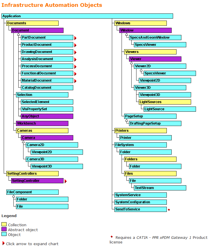 | Figure 1. Structure of automation object |
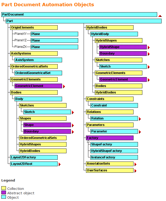 | Figure 2. Structure of part document automation object |
3. Macro Method to Generate CAD Models
- a. User formsUser forms are the custom user interface screens that can be developed in VBA to interact with the users. Creating a user forms is an important feature in Visual Basic program. User form gives the ability to easily and quickly create graphical user interface for the VB programs. The fundamental of any GUI in a VB program is a “Form”. Form control are objects which can be place on Excel worksheet or User forms, which give the functionality to interact with the data and onto which various text fields, buttons, list fields, menu strip, etc. may be dragged. User can choose from a list of option from list box, drop down box, spinners and by scroll bars. Check boxes and option button allow selection of various options and buttons allow execution of VBA codes.User form used in the automation process by using macro method is as shown in Fig 3. It helps the user to interact with the model. The user form contains text boxes, labels and a command button. Labels are used to show the message or to identify the parameters needed to edit in the text box. Text box is used to take the parameters to execute in the program. Command button is used to run the intended task.
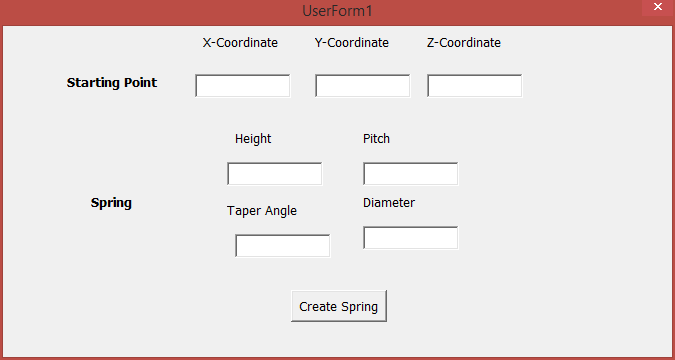 | Figure 3. User form in macro method |
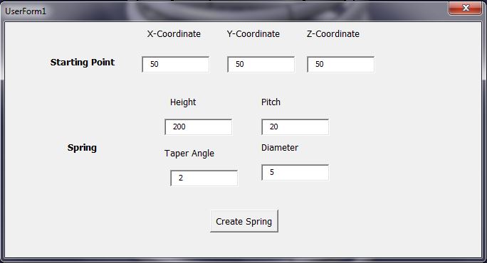 | Figure 4. Input Parameter Form |
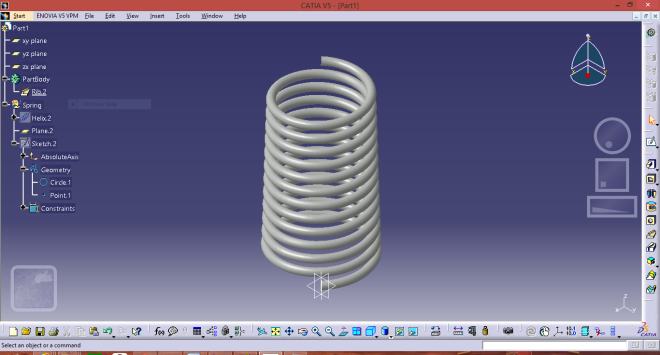
 | Figure 5. Generation of spring |
4. Manual Program to Generate CAD Models
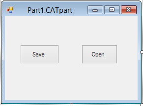
- a. User forms Fig 6 shows the user form used in the automation process using the manual programming method, which helps in user interaction with the model. The title of the user form shows the part name. The user form contains only two buttons namely ‘save’ and ‘open’ tools. Save tool is used to save the parameters in text format and open tool is used to read the edited parameters.
 | Figure 6. User form in manual programing method |
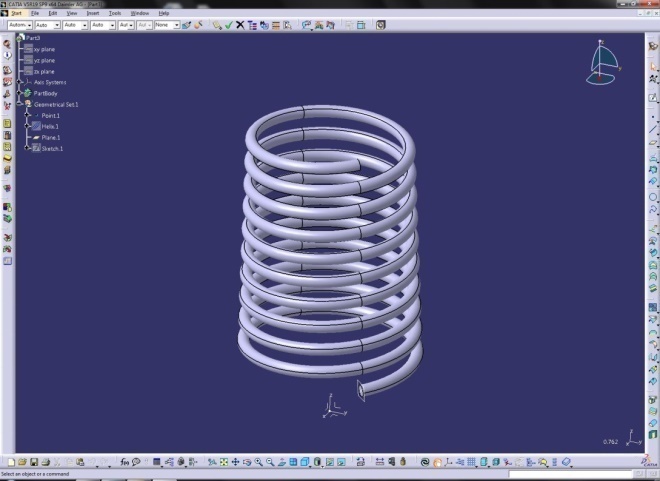
 | Figure 7. Spring |
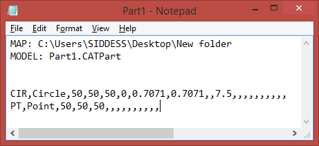 | Figure 8. Saved file |
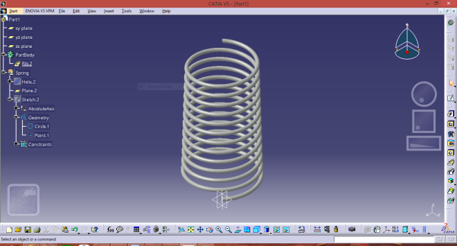
 | Figure 9. Updated spring |
5. Results
- The automation of generating CAD models results in following benefits: 1. The time required for the generation of CAD models for repetitive work is reduced tremendously. Approximately 90% of engineering time is saved. 2. Repetitive CAD modeling can be easily performed. 3. Large part files can be easily handled. 4. Generation of errors in manual method is completely eliminated in the proposed method.
6. Conclusions
- The work proposes an automation method over the existing procedure for generating repetitive CAD models. The proposed method is tested for various input parameters on a spring CAD model and the following conclusions are drawn.1. By using CAD automation process, it is possible to design the product without any user interactions. 2. Automation of generating the CAD models not only saves the time, but also increases the quality of input files and reduces possibility of human errors. 3. Design cost is reduced.It is also concluded that macro method is easy to use and create simple CAD models. Manual programming method is comparatively difficult but is applicable for all the CAD models of the hybrid bodies.