A. A. Chalekar , S. A. Daphal , A. A. Somatkar , S. S. Chinchanikar
Mechanical Engineering Department, S. P. Pune University, V.I.I.T, Kondhwa, Pune, Maharashtra, India
Correspondence to: A. A. Chalekar , Mechanical Engineering Department, S. P. Pune University, V.I.I.T, Kondhwa, Pune, Maharashtra, India.
| Email: |  |
Copyright © 2015 Scientific & Academic Publishing. All Rights Reserved.
Abstract
Use of computer aided manufacturing helps in meeting the demand of achieving high quality casting in cost effective manner within stipulated time frame. It plays an important role not only in development of new components but also in redesign of existing components. In spite of so much research and development in this field, it is observed that most foundries still use trial and error approach for process development. The capability to produce sound casting component of high quality at the same time reducing product costs & development times is the greatest challenge for the foundry today. Elimination of defects is the key for producing sound casting. Few of most common defects found in investment cast parts are blowholes, shrinkage cavity and porosity. The study of these defects has lead to development of various theories and practices. The paper aims at providing an approach to prevent these defects by using computer simulation for process development in investment casting.
Keywords:
Casting defects, Computer simulation, Investment casting
Cite this paper: A. A. Chalekar , S. A. Daphal , A. A. Somatkar , S. S. Chinchanikar , Minimization of Investment Casting Defects by Using Computer Simulation - A Case Study, Journal of Mechanical Engineering and Automation, Vol. 5 No. 3B, 2015, pp. 43-46. doi: 10.5923/c.jmea.201502.09.
1. Introduction
Investment casting process is one of the oldest metal-forming techniques. Its origin can be traced back to 5000 years and was first used in China and Egypt. This manufacturing technique is also known as the lost wax process.The process is generally used for small castings, but has been used to produce complete aircraft door frames, steel castings of up to 300 kg (660 lbs) and aluminium castings of up to 30 kg (66 lbs). It is generally more expensive per unit than die casting or sand casting, but has lower equipment costs. It can produce complicated shapes that would be difficult or impossible with die casting, yet like that process, it requires little surface finishing and only minor machining.
1.1. Basic Steps in Investment Casting Process
The process begins with the production of a master pattern. The master pattern can be produced from plastic but wax is the most commonly used material because it melts out easily and can be reused. This wax pattern gets destroyed in the process and hence one is required for each casting to be made. A master die is required for producing these wax patterns repeatedly with dimensional accuracy. The dimensions of master die are carefully calculated taking into account all the allowances (shrinkage, manufacturing, draft, etc.) and the gates. Designing and production of master die is crucial as the quality of casting directly depends on it. Foundries today use trial and error method for getting just the right size hence, mold making consume time as well as financial resources.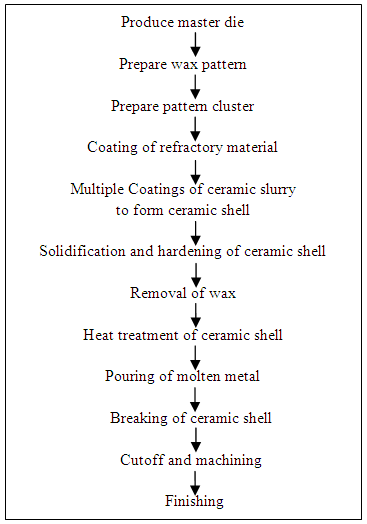 | Figure 1. Basic steps in investment casting process |
After the master patterns are produced they are attached on a wax bar along with the pouring cup. This is known as pattern cluster or tree. Then the refractory material and ceramic slurry coat is given to the tree. After the slurry forms a thick coat is allowed to dry and harden. Then the wax is melted and removed from this ceramic shell and is replaced by molten metal. The molten metal is allowed to solidify and then the ceramic shell is broken to remove the solidified metal tree. Lastly cutoff of individual casting take place which are the machined and surface finished as per requirement.
1.2. Defects
Various defects that are commonly observed in investment cast parts are blowholes, shrinkage cavity and cold shut, misrun etc.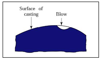 | Figure 2. Schematic of Blowholes defect |
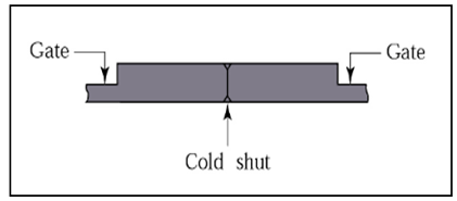 | Figure 3. Schematic of Cold shut defect |
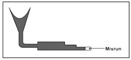 | Figure 4. Schematic of Misrun defect |
Causes and remediesThe causes for blowholes are inadequate metallostatic pressure, use of rusty scrap, moist conditions presence of liquid slag, improper degassing of liquid metal, improper gating system, turbulence while filling, too low head pressure, gas entraption due to inadequate flow-offs, risers & back pressure, interrupted/ slow pouring, cold pouring, low pouring pressure etc. [2] The volumetric contraction accompanying solidification of molten metal manifests in defects like shrinkage cavity, porosity, centerline shrinkage, corner shrinkage and sink. [2]It can be seen that the most common reason for causing defect is the improper design of gating system and volumetric contraction. The volumetric contraction problem can also be eliminated by inculcating the volumetric contraction factor while designing of gating system.Hence, we will primarily focus on validation of gating system using computer simulation rather than using trial and error method. This will help is saving time as well as financial resources.
1.3. Computer Simulation
Many casting simulation packages are now available in the market that can handle flow of molten metal and solidification in the casting with satisfactory accuracy [1]. Computer aided process simulation been available for the past fifteen years. In spite of this, many investment casters still use the conventional trial and error approach for process development. 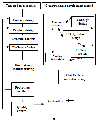 | Figure 5. Computer aided development vs. Trial and error development [1] |
It is observed that in most of the foundries, there is no conversation between the foundry engineer and the design facility in early stages of product development. The foundry engineer has to follow all stringent specifications given by the designer and is under tremendous pressure of producing sound casting within stipulated time frame and in given budget [1]. Also, the defects can be analyzed only after actual prototype of casting is made. This leads to wasting of resources.Computer Simulation provides valuable information that facilitates participation by the foundry engineer early in the product development stage [1]. This reduces the time between the concept stage and production stage in the life of a new component.
2. Case Study – Piston of Piston Valve
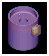
In this case foundry is producing 100 NB pistons for first time. This casting has a slightly complicated geometry. In case defects are observed after prototype production the rework cost will be very high. Hence, instead of redesigning the mould several times in trial and-error fashion, the gating and risering was designed with the assistance of computer modelling.3 dimensional model is prepared in CATIA- V5 as shown in figure 6. The left side of figure shows the isometric view while the right side shows the bottom view of piston. The piston is 121 mm in length having outer diameter and inner diameter as 94 mm and 82 mm respectively. It consists of 8 ribs as shown in fig. 6.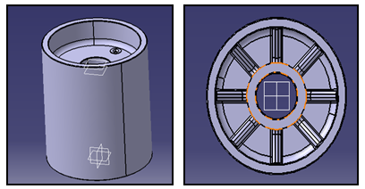 | Figure 6. Three dimensional model of piston |
After the model is prepared, allowance factor is calculated and the model is then scaled by allowance factor. Gates need to be attached to this scaled model as inlet for molten metal. The position of gates is a crucial factor in patter designing. The gate is attached at a section of casting which will be last to freeze, also known as hotspot. So, a computer simulation is done using online simulation to find out the section that will be last to freeze. The figure 7 shows the output of the simulation. The blue color indicates early freezing region whereas the white color band is the hottest region that means it will be the slowest freezing section where the gate is to be attached.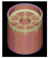 | Figure 7. Simulation result of piston |
The gate dimensions are calculated and the gate is attached to the 3D model as shown in figure 6. This is known as wax-pattern. Again a check is carried out to verify the dimensions of the gate. The simulation indicates that the gate is hotter than the casting, solidification will be directional and any air bubbles if present will rise towards the gate. Thus, eliminates blowhole defect.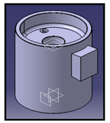 | Figure 8. Three dimensional model of wax-pattern |
 | Figure 9. Simulation result of wax-pattern |
The 3D model of tree or cluster is then prepared and simulation is done. If the feeders are hotter than the casting it means that they will freeze after the casting and the molten metal in the feeders will compensate for volumetric shrinkage and avoid any underfill or cavity defect.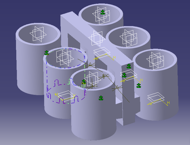 | Figure 10. Three dimensional model of cluster |
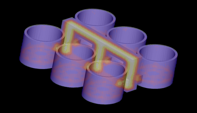 | Figure 11. Simulation result of cluster |
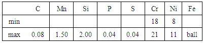
Thus, we have validated the feeding system and we know that the casting will be free from defects mentioned above.Table 1. Chemical composition of CF8 - corrosion resistant steel
 |
| |
|
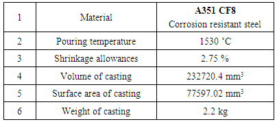
Table 2. Input data for simulation
 |
| |
|
3. Conclusions
In this case study, we minimized the defects that can be caused due to faulty design of gating system and master die by using CATIA V5 and simulations. The above data can be further used to calculate the correct dimensions of die thus eliminating the trial and error approach.The use of computer aided manufacturing helps a lot in saving the time and financial resources. The defects can be substantially minimized by using specialized software for casting simulation.
References
| [1] | Vipul M Vasava, Prof D.R. Joshi, “Identification of Casting Defects by Computer Simulation –A Review,” International Journal of Engineering Research & Technology Vol. 2 Issue 8, August – 2013. |
| [2] | Smt. R. Shri Rama Devi, “Evaluation of Blowholes and Shrinkage Defects in Investment Casting Of Low Alloy Steels,” International Journal of Engineering Research and Development Volume 9, Issue 9, January 2014. |
| [3] | Prof. A. K. M. Bazlur Rashid; The Feeding Systems, Lecture 16, Department of MME, BUET, Dhaka. |
| [4] | Wlodawer, R, “Directional Solidification of Steel Castings,” Pergamon London 1966. |
| [5] | Brooks, R. Still, “Rapid, but Much More than Prototyping,” Foundry Management & Technology March – 2012. |
| [6] | Sagar M Bechara, Dilbagsingh Mondloe, “Optimization of Gating System and Minimization of Casting Defect based on Casting Simulation: A Review”, IJSRD -Vol. 2, Issue 10, 2014. |
| [7] | Dr. B. Ravi, “Computer-aided Casting Design and Simulation” STTP, V.N.I.T. Nagpur, July 21, 2009. |
| [8] | Dr. Atul Borade, Akshaykumar Wanjari, Ashish Wankhade, Rohit Patle, “A review on casting defects thier casuses and thier remedies”, International journal for engineering applications and Technology, March 17, 2015. |
| [9] | Sarath Paul, Rathish R, “Simulation and experimental validation of feeding efficiency in FG 260 grey cast iron castings”, International Journal of Engineering Research and General Science Volume 2, Issue 6, October-November, 2014. |
| [10] | Atul A. Bhujugade, Vijay B. Sabnis 2, “Minimization of Casting Defects Using Casting Simulation Technique and Casting Defects Analysis Using Design of Experiment”, International Journal for Research in Applied Science & Engineering Technology, Volume 3 Issue VI, June 2015. |
 Abstract
 Reference
 Full-Text PDF
 Full-text HTML