Swapna L. 1, Bharath Katta 2, B. S. Suresh 1
1Department of Mechanical Engineering, B.M.S College of Engineering, Bangalore, India
2Design Department, CSIR-National Aerospace Laboratories, Bangalore, India
Correspondence to: Swapna L. , Department of Mechanical Engineering, B.M.S College of Engineering, Bangalore, India.
| Email: |  |
Copyright © 2015 Scientific & Academic Publishing. All Rights Reserved.
Abstract
A wind tunnel is a tool used in aerodynamic research to study the effects of air moving over solid objects. Aerodynamic forces on the test model are measured using force transducers, connected to the test model with beams. Integral balance is the instrument used to directly measure the aerodynamic forces and moments acting on the model. A six component miniature force transducer is designed for measuring the three forces –lift, drag and side force and the three moments –pitching moment, yawing moment and rolling moment for the given loads and the space available within the model. Shape optimization of the drag force flexure for studying the outputs and effects on interactions has been carried out. The conventional design of the drag measuring element is to have a rectangular parallelepiped. In this paper, the behaviour of the drag force flexure for the shapes of a concave shaped flexure along its thickness and along its width is explored. The computational results showed that there is a considerable increase in the outputs for concave shaped flexure design along the thickness with marginal increase in the interactions, and the interactions reduced in the case of concave shaped flexure design along the width, which can be adopted in the future designs.
Keywords:
Wind tunnel, Store separation, Force measurement, Optimisation
Cite this paper: Swapna L. , Bharath Katta , B. S. Suresh , Shape Optimization of a Drag Force Element of a Force Transducer for Wind Tunnel Measurements, Journal of Mechanical Engineering and Automation, Vol. 5 No. 3B, 2015, pp. 33-38. doi: 10.5923/c.jmea.201502.07.
1. Introduction
In general purpose wind tunnels force and moment measurement is one of the major activities. High levels of accuracy is required for force and moment measurements as the aerodynamic data generated in wind tunnels is used for design and development of flight vehicles, for characterizing a configuration, its stability characteristics, flight trajectories, structural design of the flight vehicle and sizing of the control surface actuators. The aerodynamic data is measured by a force transducer called Balance.Store is generally referred to object like bomb, weapon, missile, rocket which will be carried on an aircraft as shown in Fig 1. 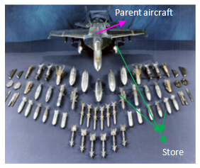 | Figure 1. Scaled down wind tunnel model and a store |
The flow field of an aircraft - store combination is non-uniform and complex, due to large variations in local dynamic pressure along both lateral and longitudinal directions. During separation, the store might exhibit erratic characteristics most of the times, in some cases after release or ejection. This problem will become severe at transonic and supersonic speeds, because of the presence of shock waves and their interaction on the store flow field. The estimation of forces and moments acting on the store should be predicted accurately for characterizing safe separation parameters. Fig 2 shows the view of store along with the parent aircraft in the wind tunnel mounted on its supports for a given grid position of the store.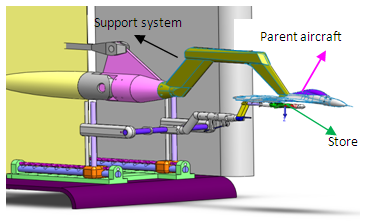 | Figure 2. Parent aircraft, store, and support systems in tunnel |
The store is mounted on the balance and which is in turn attached to the rig and the whole assembly is mounted on the test section in the wind tunnel. The work presented here comprises of design of a miniature six component force transducer to measure the forces and moments acting on the store with a size of 6mm and length of 70mm. The balance should be designed for the given size based on store dimensions, strength, sensitivity and interactions. Derived equations and Finite element method are used in an iterative process to design the structural parameters of the balance [1-2]. The balance designed by earlier researchers [3-5] has rectangular parallelepiped flexures as measuring elements. Fillet optimization of the fillet for the stress concentration region is carried by [6] on external balance. In the present work, concept of fillet optimization is applied for the entire drag force measuring element (rectangular parallelepiped flexures) of the integral balance along its width and thickness. A study has been carried out for drag force measurements based on sensitivity and interactions for rectangular parallelepiped flexure and for different shapes of flexures.
2. Design Requirements & Constraints
2.1. Requirements
The proper structural design of a balance requires accurate knowledge of the design criteria and adherence to these criteria. No explanation is presented concerning the extent to which each of these criteria exerts its influence, because their relative importance depends on the type of balance and the specific objective for which it will be used. In addition, these criteria are not independent, and many interactions exist between them. The requirements and considerations for the design of the balance are listed below:● The size of the model is a limitation for the diameter of balance which cannot exceed 6 mm.● It is designed for the loads of: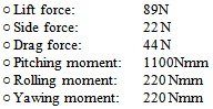 ● Large signal strains with an appropriate safety factor (acceptable sensitivity of the Wheatstone bridge): to raise the sensitivity of the Wheatstone bridge, four active strain gauges are used in the circuit. The maximum output of the Wheatstone bridge was assumed to be about 0.80 to 1.5 mV/V ● The instrument should be as stiff as possible and hence the deflection of the balance with respect to its longitudinal axis should be minimized because it brings in nonlinearity.
2.2. Output and Interaction
The output at the strain gauge locations for the measuring element with 4 active gauges forming a Wheatstone bridge is given by [4] Equation (1)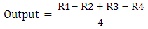 | (1) |
‘Interaction’ is the coupling between measuring elements and it should be minimum. This term ‘interaction’ in balance design is the electrical millivolt per volt output of the elements that are not being measured. Example: Drag force (DF) element strain gauge bridge reading outputs when other loads are applied is called an ‘interaction’ and the ratio of this output to the output due to DF load is known as percentage of ‘interaction’.
3. Structural Design of Transducer and Methodology
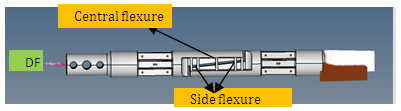
The balance has various sections as shown in Fig 3 such as mounting end, grounding end, drag section. Yawing section, pitching section and rolling section are same.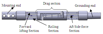 | Figure 3. Details of the force transducer |
The goal is to fabricate a balance in which the selected section was sensitive in the direction of the considered component and insensitive in the other directions. This objective can be accomplished through the proper design of the sections and appropriate wiring techniques. Four active strain gauges were used to measure each component of the balance in the Wheatstone bridge circuit. F1, F2 is the lifting force and side force applied at balance centerline (BC), M is the rolling moment; X is the distance between the forward and aft stations as shown in Fig 4.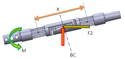 | Figure 4. Typical view of loads acting on Balance |
 | Figure 5. Pitching and yawing section |
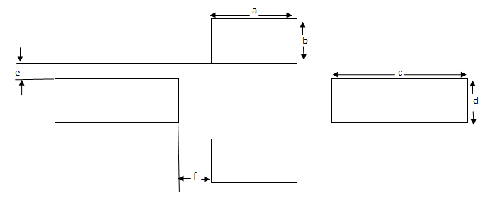
The sectional view of yawing section and pitching section is shown in Fig 5 and the equations for bending stress is derived using the bending moment equations [8]. Therefore bending stress at gauge location for normal force measuring element is given by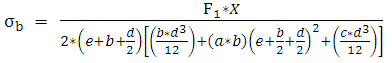 | (2) |
The bending stress at gauge location for side force measuring element is given by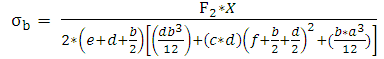 | (3) |
Where a, b, d, e, c, f are the sectional dimensions of the lifting force, rolling moment and side force measuring elements as shown in fig 4.The derived equation [1] for rolling momentsection as shown in the Fig 6 is given by equation (4) | Figure 6. Rolling moment section |
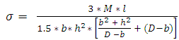 | (4) |
The DF flexures are assumed equivalent to leaf springs with no slopes at its ends deflecting with typical ‘S’ bend [7] and the tangent ends being vertical.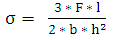 | (5) |
4. Finite Element Analysis
Finite-element analysis is carried out on the force transducer to analyse the stress and strain distribution on the measurement sections. The strain values are evaluated in the area where the strain gauges were bonded. These values were compared with those obtained from the equation. For analysis of the measurement sections, the following assumptions were made.(1) The elastic properties of the measurement sections were independent of direction.(2) The model was assumed to be perfectly elastic. A perfectly elastic model obeyed of Hook’s law.(3) There are no body forces on the measurement sections.(4) The load distributions on locations of contact of the measurement sections were uniform.The FE mesh consisted of linear tetrahedral elements. The tetrahedral elements can adjust more easily to the fillet region. The solid structure is meshed using the CTETRA elements. Grid independence was proved by taking a coarse, medium and a fine grid. Strain probes were placed at relevant locations where strain gauges need to be mounted.
4.1. Loading and Boundary Condition
The loads are applied to the balance using rigidelements to the mounting region, fixed at the grounding region as shown in Fig 7. All the loads like drag force, lift force, side force are applied independently as component loads at forward and aft sections. Rolling moment is applied about the axis of the balance.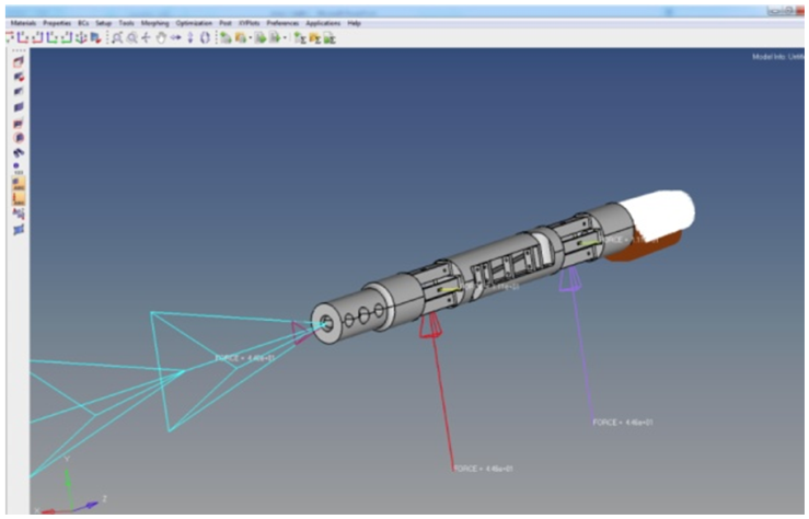 | Figure 7. Loading and boundary condition |
The flexing of the lift force measuring element at forward station takes place, when the aft lifting force is applied as shown in Fig 8. Load transfer takes place at the mounting end and it is rigidly fixed at the tapered end.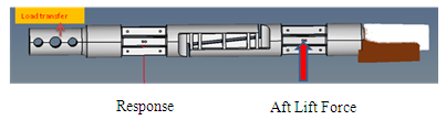 | Figure 8. Response at forward lifting force section |
The typical response of the Forward lift force measuring section is as seen in Fig 9 and gauging is as shown in the Fig 10, where the output from each strain gauge is bridged across for the outputs - equation (1), and the same response is recorded for all other component loadings. Similarly, loading at forward lifting section will give response at aft lifting force measuring section. The drag force flexure is the rectangular parallelepiped as shown in Fig 11. The drag section response is recorded at the side flexures as shown in Fig 12.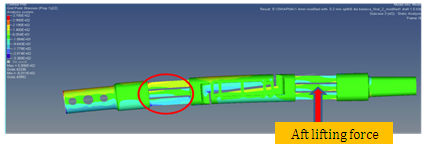 | Figure 9. Typical flexing of balance for Aft Lifting force |
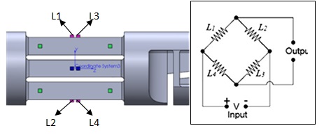 | Figure 10. Typical gauging at Aft Lifting force section and bridging |
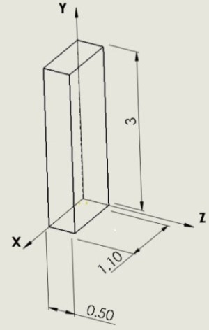 | Figure 11. Drag force flexure – Rectangular Parallelepiped |
 | Figure 12. Drag section - Responses at side flexure |
5. Stress Analysis Results
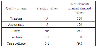
A six component - force transducer is a complex structure with different dimensions. In wind tunnel tests, combined loads are experienced on the experimental models. Such combined loads induce complicated stresses and therefore it requires special attention. In these conditions, the stress analysis of the transducer is a concern. In this loading, six components with nominal values were applied simultaneously and individually on the balance tip. The mesh configuration with CTETRA elements is shown in Fig 13. A mesh size of 0.25 mm was selected after the convergence studies. The elements are checked for the failurecriteria: warpage, aspect ratio, skewness, Jacobian and tetra collapse and the details are shown in Table 1.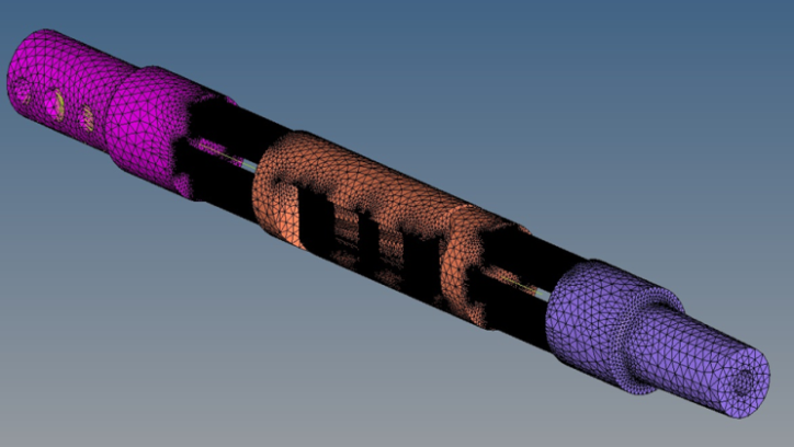 | Figure 13. Meshed model – CTETRA elements |
Table 1. Quality check of elements
 |
| |
|
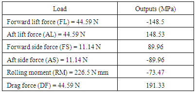
There are six Wheatstone bridge formed: Forward lift force bridge (FLB), Aft lift force bridge (ALB), Forward side force bridge (FSB), Aft side force bridge (ASB), Rolling moment bridge (RMB) and Drag force bridge (DFB) to obtain the outputs of the balance for the component loads. The outputs are presented in Table 2. Table 2. Outputs of the balance
 |
| |
|
For a given load and balance geometry, the strain output depends on the balance material used. The selection of the balance material depends on the magnitude of the loads and the maximum allowable strain level at the gauge station. Hence the material selected for the balance design is MDN 250 with yield strength of 1700MPa. The maximum stress for the balance due to combined loading is 810MPa Ref Fig 14 thereby ensuring a factor of safety of 2 as per NAL tunnel guidelines [9].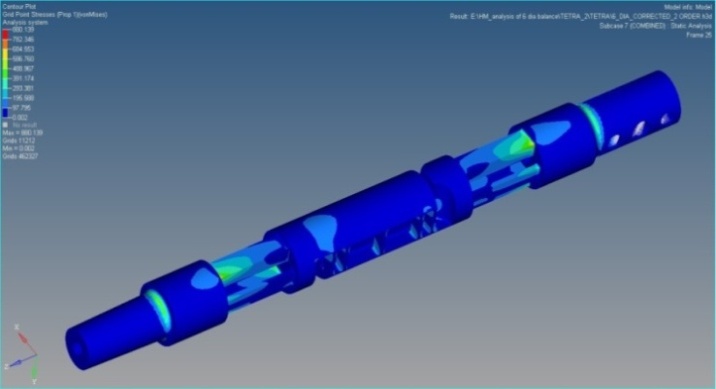 | Figure 14. Stress plot |
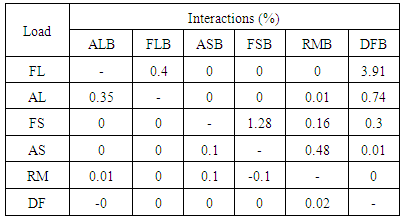
Interactions of the balance for the component loads are presented in Table 3. The maximum interaction is due to forward lift force of 3.9% on dragforce bridge.Table 3. Interactions of the balance
 |
| |
|
6. Shape Optimisation of Drag Force Member
The interaction in the drag force member was higher in the regular rectangular shape (refer Fig 11) of a drag force member. The interaction behaviour with the change in the drag force section was studied with two shapes.The drag force element in concept 1 is designed as a concave shaped flexure along its width (x-direction) as shown in the Fig 15 and is analysed for outputs and interactions. The outputs are obtained at the same optimised gauge locations. The outputs and interactions calculated are tabulated in table 4 and table 5. 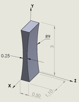 | Figure 15. Concept 1 |
Table 4. Outputs of balance for concept 1
 |
| |
|
Table 5. Interactions for concept 1
 |
| |
|
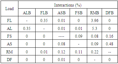
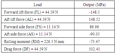
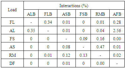
In concept 2 drag force element is designed as a concave shaped flexure along its thickness along Z-direction as shown in the Fig 16 and the analysis is carried out for all the individual and combined loads. The outputs obtained and interactions calculated are tabulated in the table 6 and table 7.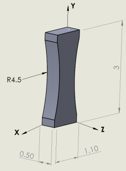 | Figure 16. Concept 2 |
Table 6. Outputs of balance for concept 2
 |
| |
|
Table 7. Interactions for concept 2
 |
| |
|
7. Conclusions
● The integral balance is designed within the space constraint of Ø 6mm for strength, deflection, maximum outputs and minimum Interactions.● The Wheatstone bridge at Drag force element gives maximum outputs with minimum interactions on the side flexure with 4% interaction for lift force.● The results due to Shape optimisation on Drag Force element shows that the Wheatstone bridge outputs at lifting force elements, side force elements and rolling moment elements are not varied much and thereby there is nosignificant influence on interactions, whereas the outputs at drag element has varied, hence its influence on interactions and outputs are studied.● The shape optimisation of drag force element shows that for concept 1 the outputs can be increased twice that is from 85MPa to 191MPa with just a marginal increase in the interactions from 4% to 5% and for Concept 2 the outputs are increased marginally from 90MPa to 108MPa but the interactions is reduced from 4% to 2.5%.● The analysis of different shapes of drag force flexures shows that by optimising the shapes of flexural elements better results can be obtained as per the requirement.● The shape optimisation concept for Drag Force flexures can be applied to Lifting force and Side force sensing elements and a further study can be taken up to study its effects on outputs.
ACKNOWLEDGEMENTS
The authors gratefully acknowledge the CSIR-National Aerospace Laboratories, Bangalore for providing the opportunity to carry out the work at Design Section, NTAF, NAL and BMS college of engineering, Bangalore.
References
| [1] | N.M. Nouri, Karim Mostafapour, Maryam Kamran, Robab Bohadori, “Design methodology of a six-component balance for measuring forces and moments in water tunnel tests” Measurement 58(2014) 544-555. |
| [2] | Marin Sandu, Adriana Sandu, Georgeta, “Design of a compact six-component force and moment sensor for aerodynamic testing” INCAS BULLETIN, Volume 3, ISSN 2066 – 8201, pp. 95-100, 2011. |
| [3] | A.L. Smith, D.J. Mee, W.J.T. Daniel, T. Shimoda, “Design, modelling and analysis of a six component force balance for hypervelocity wind tunnel testing”, Computers and Structures 79(2001)1077-1088. |
| [4] | Rajeev G “A high Drag Balance for Aerodynamic Force and Moment Measurements” in: Proceedings of the 9th International Symposium on Strain-Gauge Balances, Seattle, USA, May 2014. |
| [5] | V.V. Bogdanov, et. al., “Internal Six-Component Strain-Gage Balances with Band Suspension” in: Proceedings of the 9th International Symposium on Strain-Gauge Balances, Seattle, USA, May 2014. |
| [6] | Keith C. Lynn Genevieve, et.al., “Flexural Fillet Geometry Optimization for Design of Force Transducers used in Aeronautics Testing” in: Proceedings of the 9th International Symposium on Strain-Gauge Balances, Seattle, USA, May 2014. |
| [7] | M.F Spotts, Design of machine elements, Second Edition, Prentice Hall, Inc, 1953. |
| [8] | Warren C Young, Roark formulas for stress and strain, 6th Edition, McGraw - hill International Editions. 1989. |
| [9] | Rajeev. G, et.al, General Guidelines for design of Models for Wind tunnel Testing at NTAF, Project Document NT 0606, pp. 1-4, 2006. |
 Abstract
 Reference
 Full-Text PDF
 Full-text HTML