Anil Kumar K. S. , Anup S. Karur , Shravan Chipli , Ankith Singh
Department of Mechanical Engineering, JSS Academy of Technical Education, Bangalore, Karnataka, India
Correspondence to: Anil Kumar K. S. , Department of Mechanical Engineering, JSS Academy of Technical Education, Bangalore, Karnataka, India.
| Email: |  |
Copyright © 2015 Scientific & Academic Publishing. All Rights Reserved.
Abstract
Friction Stir Welding(FSW) was carried out on commercially available Aluminum Alloy 2024-T351 plates with dimensions of 100×100×6.35 mm. Design of experiment (DOE) was applied to determine the most important factors which influence Ultimate Tensile Strength (UTS) and hardness of AA 2024 T-351 joints produced by Friction Stir Welding (FSW). Effect of three factors which include tool rotational speed, welding speed and tool tilt angle on UTS and hardness were investigated. By Taguchi method using L9 orthogonal array, the optimum of process parameters was determined. ANOVA analysis was carried out to determine the percentage contribution of each factor on Tensile Strength and Hardness. Tensile strength of welded joints increased with increasing in rotational speed from 355rpm to 560 rpm, traverse speed from 12.5mm/min to 20 mm/min but further increase in the rotational speed from 560rpm to 900rpm decreased the tensile strength of the joints. Hardness value increased with increasing rotational speed, traverse speed and a tool tilt angle of 0 and 1 degree.
Keywords:
Friction Stir Welding, Optimization, Taguchi Method, ANOVA Analysis
Cite this paper: Anil Kumar K. S. , Anup S. Karur , Shravan Chipli , Ankith Singh , Optimization of FSW Parameters to Improve the Mechanical Properties of AA2024-T351 Similar Joints Using Taguchi Method, Journal of Mechanical Engineering and Automation, Vol. 5 No. 3B, 2015, pp. 27-32. doi: 10.5923/c.jmea.201502.06.
1. Introduction
Friction stir welding (FSW) is a relatively new solid-state joining process. This joining technique is energy efficient, environment friendly, and versatile. In particular, it can be used to join high-strength aerospace aluminum alloys and other metallic alloys that are hard to weld by conventional fusion welding. FSW is considered to be the most significant development in metal joining in a decade [1, 2]. FSW has evolved as a technique of choice in the routine joining of aluminium components; its applications for joining difficult metals and metals other than aluminium are growing. There have been widespread benefits resulting from the application of FSW in for example, aerospace, shipbuilding, automotive and railway industries. The difficulty of making high-strength, fatigue and fracture resistant welds in aerospace aluminum alloys, such as highly alloyed 2XXX and 7XXX series, has long inhibited the wide use of welding for joining aerospace structures. These aluminum alloys are generally classified as non-weldable because of the poor solidification microstructure and porosity in the fusion zone. Also, the loss in mechanical properties as compared to the base material is very significant. These factors make the joining of these alloys by conventional welding processes unattractive. Some aluminum alloys can be resistance welded, but the surface preparation is expensive, with surface oxide being a major problem.As compared to the conventional welding methods, FSW consumes considerably less energy. No cover gas or flux is used, thereby making the process environmentally friendly. The joining does not involve any use of filler metal and therefore any aluminum alloy can be joined without concern for the compatibility of composition, which is an issue in fusion welding. When desirable, dissimilar aluminum alloys and composites can be joined with equal ease. The materials used in airframe structures and in jet engine components are critical to the successful design, construction, certification, operation and maintenance of aircraft [3]. Materials have an impact through the entire life cycle of aircraft, from the initial design phase through manufacture and certification of the aircraft, to flight operations and maintenance and, finally, to disposal at the end-of-life. Aluminum alloys are very promising for structural applications in aerospace, military, and transportation industries due to their low density, high specific strength and resistance to corrosion, and especially regarding high energy cost. AA 2024 is an aluminium alloy, with copper as the primary alloying element. It is used in applications requiring high strength to weight ratio, as well as good fatigue resistance. It is weldable only through friction welding, and has average machinability.To carryout friction stir welding, the various performance input parameters [4, 5] arranged in their descending order of contribution are defined below;1) Tool rotation speed2) Traverse speed3) Tool geometry4) Tilt angle5) Axial load6) Plunge depth7) Backing plateThe three important parameters i.e Tool rotation speed (rpm), Traverse speed (mm/min) and Tool geometry are discussed below.Friction stir welding process includes two main parameters, one is the tool rotation speed and the other is the welding speed. These two parameters dominate the quality and mechanical properties of friction stir welded joints. Welding parameter effects on microstructure, mechanical property and residual stress profiles of FSW joints have been studied by several researchers. [6-12] The major conclusions of this work are as follows.(1) The weld properties are dominated by the heat input rather than the mechanical deformation by the tool [6–12].(2) The grain size in the welded zone increases with the increasing tool rotation speed or the decreasing welding speed(3) The yield strength (YS) and the ultimate tensile strength (UTS) of welded joints increase with the decreasing tool rotation speed or the increasing welding speed.(4) The width and maximum of the residual stress profiles show clear correlation with the heat input, and in particular welding speed, which was found to be the dominant parameter.Tool geometry is the most influential aspect of process development. The tool geometry plays a critical role in material flow and in turn governs the traverse rate at which FSW can be conducted. An FSW tool consists of a shoulder and a pin as shown schematically in Figure 1. As mentioned earlier, the tool has two primary functions: (a) Localized heating and (b) Material flow.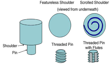 | Figure 1. Some examples of tool geometries [1] used in FSW |
In the initial stage of tool plunge, the heating results primarily from the friction between pin and work piece. Additional heating results from deformation of material.The tool is plunged till the shoulder touches the work piece. The friction between the shoulder and work piece results in the biggest component of heating. From the heating aspect, the relative size of pin and shoulder is important, and the other design features are not critical. The shoulder also provides confinement for the heated volume of material. The second function of the tool is to ‘stir’ and ‘move’ the material. The uniformity of microstructure, properties and process loads are governed by the tool design. Tool design influences heat generation, plastic flow, the power required, and the uniformity of the welded joint. The shoulder generates most of the heat and prevents the plasticized material from escaping from the work-piece, while both the shoulder and the tool pin affect the material flow. Numerous efforts have been devoted to understand the relationship between tool parameters (including geometric shape, dimensions and thread features) and mechanical microstructural properties of different alloys within a wide range of welding conditions. FSW tool pins are often featured with thread forms.
2. Experimental Procedure
The tool used is cylindrical tool is shown in figure 2. It is made of high speed steel (HSS). It is used to fabricate the joints. The tool has a shoulder diameter of 25mm, pin diameter of 10mm and pin length of 6mm. The rotating tool is specially designed such that the pin inserts into the abutting edges of plates to be joined and traversed along the line of joint, also the shoulder exerts external pressure and also generates enough heat from friction between the shoulder and work piece to form a strong joint.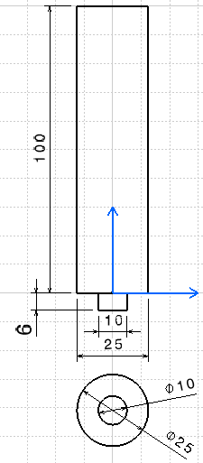 | Figure 2. Dimensions of HSS tool used to in preparing FSW joints in mm |
In this study, commercially available AA2024-T351 were procured in the form of plates of dimension 100mm×100mm×6.35mm. A total of 24 plates were used to produce similar FSW butt joints as shown in figure 3. Edges of sheared faces were milled on a vertical milling machine to obtain good surface finish and checked and ensured for perpendicularity. Also, the edges were rubbed with emery paper and cleaned with acetone before welding the joints to remove all the dirt and grit.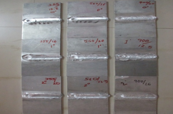 | Figure 3. Weld joints for different combination of welding parameters |
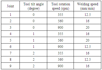
Trial experiments were carried out according to the principles of the design of the experiments in order to determine the effect of the main process parameters. An L9 orthogonal array with five columns and nine rows was applied. The experimental layout for the three welding parameters using the L9 orthogonal array is shown in Table 1.Table 1. L9 orthogonal array or input variables
 |
| |
|
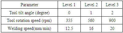
Based on the input parameters already determined, welding was carried out for each of the 9 combinations. The machine used was a modified milling machine to perform friction stir welding. The direction of welding is normal to the rolling direction. Single pass welding procedures are used to fabricate the joints.The parameters we have considered for investigation are tool rotation speed, traverse speed and tool tilt angle. The selected process parameters and the levels are shown in the table 2. Table 2. Process parameters and their levels
 |
| |
|
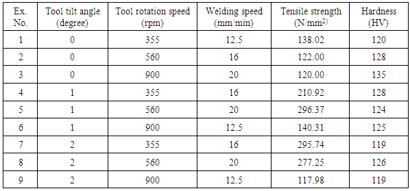
The stirring and mixing of materials around the rotating pin is done by the rotation of tools thus stirs material from the front to the back of the pin and finishes the welding process. Since the tool rotates at high speed it generates high temperature because of higher friction heating and result in more intense stirring and mixing of material. Thus increases in heat are directly proportional with the tool rotation rate is not expected as the coefficient of friction at interface will change with increasing tool rotation rate. Table 3 shows the different experiments conducted based on taguchi L9 orthogonal array and the test results. Table 3. Table showing Tensile strength and hardness value for different input parameters
 |
| |
|
The weld joints were obtained is in fig 4. Welded specimens were tested for Tensile strength, Yield strength and hardness at Raghavendra Spectro Metallurgical Laboratory located at Peenya, Bangalore.Tensile test was conducted along the normal to the weld line, that is, parallel to the grain direction in a Universal Testing Machine to obtain the properties. Tensile test was conducted on Universal Testing Machine (TUE-600C) in accordance with ASTM E8 standard. Before testing, the specimens were machined as per ASTM E8 standard for a flat test specimen.The specimen after subjecting to ultimate tensile test is as shown in figure 4 and figure 5.  | Figure 4. Specimen as subjected to tensile test |
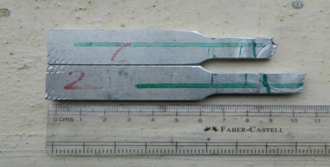 | Figure 5. Figure showing the point of breakage |
Vickers hardness test was conducted at three locations such as weld nugget zone and heat affected zones on either side of the nugget zone.
3. Results and Discussion
3.1. Tensile Test and Hardness Test Results
From the tensile test conducted on different specimen prepared as per ASTM E8 standards , tensile strength, yield strength and percentage elongation were obtained for each weld joint and from Vickers hardness test, hardness was obtained at three different locations, one along the weld zone and two on the heat affected zones on either side of the weld zone. Only Tensile strength and hardness along the weld zone of each weld joint are considered for optimization. All the values obtained are tabulated in table 3.
3.2. Optimization by Taguchi Method
In order to optimize FSW process parameters, the tensile strength and hardness were analyzed. To assess the influence of factors on the response, the means and S/N ratios for each control factor can be calculated. In this study, the S/N ratio was chosen according to the criterion of the larger-the-better, in order to maximize the response. The signal to noise ratios (S/N), which are log functions of desired output, serve as the objective functions for optimization, help in data analysis and the prediction of the optimum results The S/N ratio is calculated using the larger-the-better criterion and is given by,
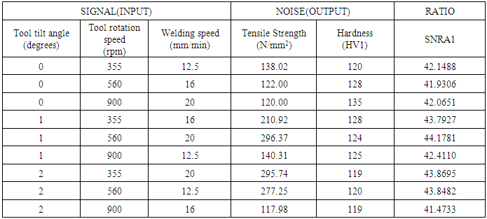
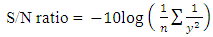 Where y is the observed data and n is the number of observations. The obtained tensile strength and hardness were converted into S/N ratio. The experimental results and calculated S/N ratio values are tabulated in table 4.
Table 4. Experimental results and corresponding Signal to Noise ratios
 |
| |
|
S/N ratio against the design factors as obtained by the Minitab Software is shown in figure 6.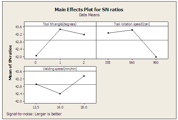 | Figure 6. S/N ratio plot for different input parameters |
Response optimization helps to identify the combination of input variable settings that jointly optimize a single response or a set of responses. Based on the highest values of the S/N ratio and the signal- to- noise ratio plot fig 6., obtained by the Minitab software and with values in table 4, Tensile strength of welded joints increased with increasing in rotational speed from 355rpm to 560 rpm, traverse speed from 12.5mm/min to 20 mm/min but further increase in the rotational speed from 560rpm to 900rpm decreased the tensile strength of the joints. Hardness value increased with increasing rotational speed, traverse speed and a tool tilt angle of 0 and 1 degree. It can be inferred that the optimum friction stir welding parameters for AA 2024-T351 using cylindrical pin profiled tool are 1. Tool rotation speed: 560 rpm2. Welding speed: 20 mm/min3. Tool tilt angle: 1 degree After the optimum condition was determined, the optimum performance of the response under the optimum condition was predicted. The optimum value of the response characteristic is estimated as follows [13],
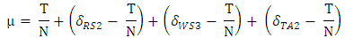 Where T / N is overall mean of tensile strength,
  is Average tensile strength at second level of rotational speed,
  is Average tensile strength at third level of welding speed,
  = Average tensile strength at second level of tool tilt angle. Substituting the values of various terms in the above equation gives
  predicted value.
 = 178.63 + (231.8 – 178.63) + (237.37 -178.63) + (215.86 – 178.63)
 = 327.77 N/mm2Where
  is the predicted value of tensile strength. The experimental value for the obtained optimum combination is 296.37 N/mm2. Hence the predicted value ‘
 ’ is close to the experimental value with deviation of 10.59%.
3.3. ANOVA Analysis
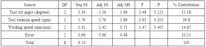
The main purpose of the ANOVA [16] is the application of a statistical method to identify the effect of individual factors on the process response. Results from ANOVA can determine very clearly the impact of each factor on tensile strength and hardness. The ANOVA table for S/N is calculated and listed in table 5.Table 5. Analysis of Variance for S/N ratio
 |
| |
|
The Taguchi experimental method could not judge the effect of individual parameters on the entire process, thus the percentage of contribution using ANOVA is used to compensate for this effect. Percent contribution indicates the relative power of a factor to reduce variation. For a factor with a high percent contribution, a small variation will have a great influence on the performance. The percentage of contribution (fi) is a function of the sum of squares for each significant item and can be calculated as
 Where
Where  is the
  factor, SSfi is the pure sum of squares for
  SeqSStotal is the total mean of sequential sum of squares. From the table 3, it can be inferred that tool rotation speed as a major percent contribution in improving mechanical properties followed by tool tilt angle and welding speed.
4. Conclusions
In this study, the Taguchi method was used to obtain optimum conditions for friction Stir Welding (FSW) of AA2024 T-351. Experimental results were evaluated using ANOVA tool. The influence of tool rotation speed, welding speed and tool tilt angle on joint quality in 2024-T351 aluminum alloy was established. The specimens were subjected to friction stir welding with the rotation rates of 355, 560 and 900 r/min and welding speed between 12.5, 16 and 20 mm/min, providing tool tilt angle of 0, 1 and 2 degree. The welded joints was tested for tensile strength and hardness.The FSP process parameters were optimized to maximize the tensile strength and hardness. The optimum condition of the rotational speed, transverse speed and tool tilt angle were found to be 560 r/min, 20 mm/min and 1 degree respectively.It was found that tensile strength increased with increasing in speed from 355rpm to 560 rpm, but further increase in the speed from 560rpm to 900rpm, the tensile strength of the joint decreased. It was also found that increase in traverse speed from 12.5mm/min to 20 mm/min, increased the tensile strength. From trial and error methods, it was understood by visual inspection that for rotational speeds of 1200rpm and above surface defects were extremely prominent. For lower than 355rpm the bonding was poor. The rotational speed is found to be the important influential process parameter with 39.80% contribution followed by tool tilt angle (35.18%) and welding speed (14.87%) respectively.A maximum tensile strength of 296.37 N/mm2 was exhibited by the FSW joint fabricated with optimized parameter of 560rpm rotational speed, 10 tilt angle and 20 mm/min welding speed. Tool rotation speed was the major factor contributing to tensile strength.The scope for further studies would be to carry out the FSW process using the optimized parameters mentioned above, making use of a cylindrical profiled tool. Much attention needs to be vested on the tool rotation speed as it contributes the maximum to the mechanical properties.
ACKNOWLEDGEMENTS
The authors would like to thank for the support given by the Welding Research Institute (WRI), Trichy, which is a PSU under BHEL for experimental work.
References
| [1] | R.S. Mishra, Z.Y. Ma, Friction Stir Welding and processing. Materials Science and Engineering R 50 (2005) 1–78. Review journal. |
| [2] | R Nandan, T.B. Debroy, H.K.D.H. Bhadeshia, Recent advancement in friction stir welding – Process, weldment structure and properties. Progress in Materials Science 53 (2008) 980–1023. |
| [3] | Adrian P. Moutitz, Introduction to aerospace materials. Woodhead Publishing Limited, 2012. |
| [4] | C. Elanchezhian, B. Vijaya Ramnath, P. Venkatesan, S. Satish, T. Vignesh, B. Vinay, K. Gopinath, Parameter optimization of FSW of AA8011-6062 using mathematical model. 12th Global congress on manufacturing and management, GCMM 2014. Procedia Engineering 97 (2014) 775 – 782. |
| [5] | C. Genevois, A. Deschamps, P. Vacher, Comparative study on local and global mechanical properties on AA 2024-T351, 2024-T6 and 5201 Friction Stir Welds. Materials Science and Engineering A 415 (2006) 162–170. |
| [6] | Qian JW, Li JL, Sun F, Xiong JT, Zhang FS, Lin X. An analytical model to optimize rotation speed and travel speed of friction stir welding for defect-free joints. Scripta Mater 2013; 68:175–8. |
| [7] | Lombard H, Hattingh DG, Steuwer A, James MN. Effect of process parameters on the residual stress in AA5083-H321 friction stir welds. Mater Sci Engng, A 2009; 501:119–24. |
| [8] | Yuan W, Mishra RS, Webb S, Chen YL, Carlson B, Herling DR, et al. Effect of tool design and process parameters on properties of Al alloy 6016 friction stir spot welds. J Mater Process Technol 2011; 211: 972–7. |
| [9] | Hao HL, Ni DR, Huang H, Wang D, Xiao BL, Nie ZR, et al. Effect of welding parameters on microstructure and mechanical properties of friction stir welded Al–Mg–Er alloy. Mater Sci Engng, A 2013; 559: 889–96. |
| [10] | Dong P, Li HM, Sun DQ, Gong WB, Liu J. Effects of welding speed on the microstructure and hardness in friction stir welding joints of 6005A-T6 aluminum alloy. Mater Des 2013; 45: 524–31. |
| [11] | Commin L, Dumont M, Masse JE, Barrallier L. Friction stir welding of AZ31 magnesium alloy rolled sheets: influence of processing parameters. ActaMater 2009;57:326–34. |
| [12] | Rodrigues DM, Loureiro A, Leitao C, Leal RM, Chaparro BM, Vilaca P. Influence of friction stir welding parameters on the microstructure and mechanical properties of AA 6016-T4 thin welds. Mater Des 2009; 30: 1913–21. |
| [13] | M. Salehi, M. saadatmand, J. Aghazadeh mohandesi optimization of process parameters for producing aa6061/sic nanocomposites by friction stir processing. Trans. Nonferrous Met. Soc. China 22(2012) 1055_1063. |
| [14] | Peel M, Steuwer A, Preuss M, Withers PJ. Microstructure, mechanical properties and residual stresses as a function of welding speed in aluminium AA5083 friction stir welds. Acta Mater 2003; 51: 4791–801. |
| [15] | Radisavljevic, A. Zivkovic, N. Radovic, V. Grabulov, Influence of FSW parameters on formation quality and mechanical properties of Al 2024 T-351. Trans. Nonferrous Met. Soc. China 23(2013) 3525-3539. |
| [16] | Douglas C Montgomery, Design and Analysis Experiments. 5th edition, John Wiley and Sons . 2001. |
 Abstract
 Reference
 Full-Text PDF
 Full-text HTML