A. A. Chalekar , A. A. Somatkar , S. S. Chinchanikar
Mechanical Engineering Department, S. P. Pune University, V.I.I.T, Kondhwa, Pune, Maharashtra, India
Correspondence to: A. A. Chalekar , Mechanical Engineering Department, S. P. Pune University, V.I.I.T, Kondhwa, Pune, Maharashtra, India.
| Email: |  |
Copyright © 2015 Scientific & Academic Publishing. All Rights Reserved.
Abstract
In order to reduce the process development time and maintain profit along with increasing reliability of the system, it has become necessary for foundry engineers to optimize gating system and thus prevent defects before the production of casting starts. It has been observed that location and size of feeders that provide liquid metal to compensate for shrinkage of solidifying metal are determined by the ingenuity of the foundry engineer. Even if different combinations of feeder location and size can be tried using computer simulation, the optimum design is quite difficult to obtain. Hence, geometry based approaches are still important in process design. It was observed that lot of research work has been published giving out various theories and formulas for design of feeding system but, there is little data available which show actual application of those formulas for calculating individual dimensions of feeding system in day to day use. The aim of this paper is to present a step by step guide to design a gating system for spacer which can be further generalised for any other component.
Keywords:
Design, Gating system, Modulus method
Cite this paper: A. A. Chalekar , A. A. Somatkar , S. S. Chinchanikar , Designing of Feeding System for Investment Casting Process – A Case Study, Journal of Mechanical Engineering and Automation, Vol. 5 No. 3B, 2015, pp. 15-18. doi: 10.5923/c.jmea.201502.03.
1. Introduction
In any casting process, when an alloy is poured into a mold, it starts to shrink or contract in volume as it cools down to liquidus temperature, and subsequently solidifies. These two stages of volumetric contraction are compensated by adding feeders to the mold cavity design. But unlike sand casting, in investment casting the gating/feeding elements provide dual or combined function of both.The gating/feeding system initially governs the mold filling operation and guides the molten metal as it flows into the mold filing cavity, later while solidification it guides the feeding liquid into this cavity as compensation for the first two stages of alloy contraction. There are many methods available for dimensioning of feeding elements like Caine’s method, Bishops method, Chvorinov’s rule, Wlodawer’s method etc. [2] The method used for dimensioning of feeding elements used in this case study is derived from the rules that have been formulated based on the original concepts by Chvorinov and subsequently elaborated by Wlodawer. This method is known as ‘Modulus method’. [4]
2. Modulus Method
Modulus is defined as the ratio of the volume to the cooling surface area of the casting (or a part of the casting) or the feeder.  | (1) |
Where, V is the volume of casting, or feeder A is the cooling surface area.Chvorinov’ rule [3] state that, solidification time increases as the square of volume to area ratio increase, and hence M, increase.Or, | (2) |
Where, T is solidification time, and C is constant.It is easy to calculate this ratio for simpler objects, but in real practice the objects involved are much more complex. For complicated shapes, the casting is subdivided into smaller basic shapes and modulus is calculated for each section. It should be noted that during calculations only cooling surface areas are to be included. Also, complex junctions like curves are to be approximated. Feeding requirement for each section then calculated for each section as required.As a general rule, the feeder must solidify no sooner than the casting has solidified (heat transfer criterion). Also, the feeder must contain sufficient liquid to meet the volume contraction requirement (feed volume criterion). Thus a feeder of optimum size must satisfy both of these requirements.Heat transfer criteriaAccording to Wlodawer’s technique, the modulus of the feeder should be greater than that of the casting. Thus, using a 20% factor of safety, | (3) |
Where, MF and MC are modulus of feeder and casting respectively.To avoid shrinkage cavities near the feeder neck the following ratio should be maintained: | (4) |
Where, MN is modulus of neck at the junction of CastingFeed volume criterionThe feeder should not only solidify later than the casting, it should also have enough volume to compensate the shrinkage. Feed volume requirement is give by the relation: | (5) |
Where, η = efficiency of the feeder,  β = solidification shrinkage,
 Vf = volume of the feeder, and
  Vc = volume of the casting.The feeder volume given by the feed volume requirement does not depend on the casting shape but that given by the mass transfer or modulus criterion does.The higher of the two values of feeder volume given by equations (3) and (5) is taken as the actual volume of the feeder.
3. Steps for Dimensioning Feeding System
The procedure for designing of feeding system is presented in Fig.1.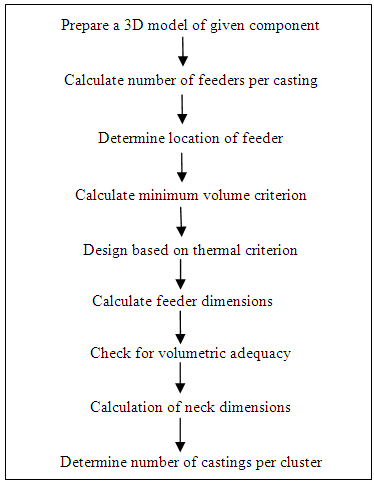 | Figure 1. Basic steps in feeding system design |
4. Case Study
In this case feeding system for producing spacers (lantern bush) is to be designed. This casting has a slightly complicated geometry. In case defects are observed after prototype production the rework cost will be very high. Hence, instead of mere manual calculations the feeding system was designed with the assistance of computer modelling.
4.1. 3D Model of Spacer
As per the 2D drawing specifications, 3D model of spacer was prepared which will be used for simulation purpose and will be helpful in verification of the theoretical design data. Fig. 2 shows the 3D model of spacer prepared using CATIA V5. Casting metal used is CA15 corrosion resistant alloy.The spacer has 4 columns; it is having outer diameter and inner diameter as 114 mm and 88 mm respectively. 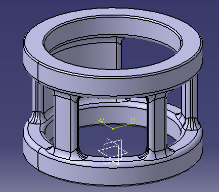 | Figure 2. 3D model of spacer |
4.2. Number of Feeders Per Castings
As the component to be cast (spacer), has no protruding parts and has simple geometry, hence the casting is fed by a single feeder.
4.3. Positioning of Feeder
The spacer is divided into 3 sections based on the change in geometry as shown in Fig 3.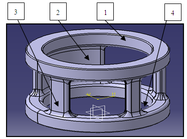 | Figure 3. Division of spacer in sections |
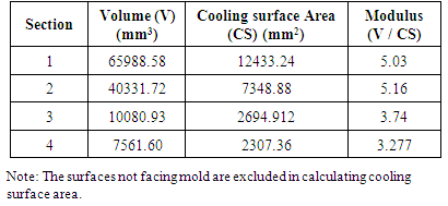
The sequence in which the sections freeze is found by calculating the modulus of each section as shown in Table 1.Table 1. Modulus of individual sections of spacer
 |
| |
|
For casting to be free from shrinkage defect, the feeder is positioned at the slowest freezing section i.e. the section having maximum modulus.As it can be seen that the maximum modulus (Mc) is found to be 5.16 and is for section 2, hence feeding element is to be attached at section 2.
4.4. Volumetric Criterion or Minimum Volume Ratio
For the feeder to have adequate volume of feed liquid to be supplied to casting being fed, following condition needs to be satisfied, Vf/Vc = {β / (η – β)}Where, Vf and Vc are the volumes of feeder and the casting sections being fed, β is alloy solidification shrinkage = 3.5 [6], η is the available feeding liquid factor = 18 [6]
 Vf/Vc = {3.5 / (18 – 3.5)}Therefore, Vf/Vc = 0.24
4.5. To Ensure That the Feeder is ‘thermally adequate’
It is very essential that the feeder freezes adequately later than the casting to be fed. MF = 1.2 * 5.16 = 6.2
4.6. Selection of Feeder
The standard feeder with square cross-section is to be selected.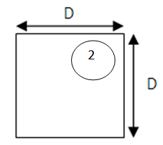 | Figure 4. Cross-sectional view of feeder |
Length of side of cross section (D) = MF * 4 = 24.88 mmThe standard square feeders available at the foundry are – i. Cross-section = 18mm * 18mm, length = up to 300mmii. Cross-section = 25mm * 25mm, length = up to 300mmiii. Cross-section = 30mm * 30mm, length=up to 250mmThe feeder with side 25 mm and length 200 mm is selected.
4.7. To Ensure That the Feeder is ‘Volumetrically Adequate’
At 150 mm length the volume of feeder,  VF = D * D * L
  = 125000 mm3Total volume of casting,VC = 123972.83 mm3Therefore, this feeder has volume ratio of VF/VC = 1.008 when attached to a single casting. 1.008 > 0.24 (volumetric criterion satisfied). Theoretically 4(1.008/0.24) castings can be cast per feeder. But, due to length restriction of feeder only 3 spacers are attached per feeder.
4.8. Calculation of Neck Dimensions
Feeder is connected to the casting by means of ‘feeder neck’. The feeder neck has a reduced cross-section than that of feeder, for ease of removal of feeders while cutoff and also to control the temperature gradients. For the casting to be free from shrinkage defects or bubble cavities, it is essential that the neck solidifies after the casting and before the feeder.Modulus of neck is given by, MN = 1.1 * 5.16
 = 5.676
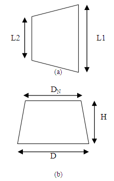 | Figure 5. Dimensions of feeder neck (a) Side view (b) Top View |
4.9. Calculation of Neck Dimensions
 MN = 1.1 * 5.16
 = 5.676Minimum dimension of neck, DN = 4 * MN = 22.704 mmi. We take DN = 23 mm (reduced over distance of H=15mm)ii. We take L = 25 mm iii. And, L2 = 23 mm
4.10. 3D Model of Wax-Pattern
The 3D model of wax-pattern attached with feeder neck is prepared by scaling the 3D model of spacer by a factor of 2.24 (patternmaker’s shrinkage allowance) and attaching a neck as per calculated dimensions as shown in Fig. 6.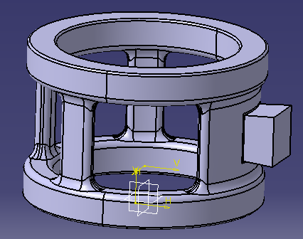 | Figure 6. 3D model of Wax-pattern of spacer |
4.11. 3D Model of Cluster
Cluster is assembly of number of wax patterns to a feeding system so as to cast them simultaneously. As calculated earlier 3 wax patterns are attached to a single feeder. The 3D model of cluster is as shown in fig. 7.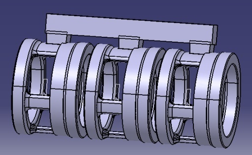 | Figure 7. 3D model of cluster |
5. Conclusions
Trial and error approach for designing feeder leads to either one of following conditions. 1. Underestimation which causes improper filling of mold and gives rise to defects like blowholes, underfill, etc. 2. Overestimating which causes wastage of financial resources related with melting of metal and component finishing.The step by step guide provided in this paper, established by Wlodawer eliminated all above drawbacks. The advantage of following above procedure is that the correct dimensions are obtained in first attempt itself. The calculated dimensions can be verified before actual production by using the 3D models for computer based simulation purpose.Geometrical approach for designing can replace the traditional way of trial and error commonly used in industries today. This will lead to reduction in time between the concept and manufacturing phase by a significant amount. Also, the cost of rework and redesign is eliminated increasing profit of industry.
References
| [1] | Vipul M Vasava, Prof D.R. Joshi, “Identification of Casting Defects by Computer Simulation – A Review, IJERT Vol. 2 Issue 8, August – 2013. |
| [2] | “The Feeding Systems”, Lecture 15, Prof. A. K. M. Bazlur Rashid, Department of MME, BUET, Dhaka. |
| [3] | “The Feeding Systems”, Lecture 16, Prof. A. K. M. Bazlur Rashid; Department of MME, BUET, Dhaka. |
| [4] | Wlodawer, R, “Directional Solidification of Steel Castings,” Pergamon London 1966. |
| [5] | “Steel castings handbook”, Supplement 8. |
 Abstract
 Reference
 Full-Text PDF
 Full-text HTML