Baskara Sethupathi P. 1, Muthuvel A. 2, Prakash N. 2, Stanly Wilson Louis 3
1Department of Automobile Engineering, SRM University, Chennai, India
2Department of Automobile Engineering, Hindustan University, Chennai, India
3Department of Automobile Engineering, Velammal Engg Collge, Chennai, India
Correspondence to: Muthuvel A. , Department of Automobile Engineering, Hindustan University, Chennai, India.
| Email: |  |
Copyright © 2015 Scientific & Academic Publishing. All Rights Reserved.
Abstract
One area that has been examined for weight reduction is vehicle with braking system (BS). The greatest advantages of vehicles, is their ability to recover significant amounts of braking energy using a Braking System (BS). Braking is an effective method to extend brake disc life, minimise disc rotor weight, minimise brake pad wear and to extend the working range of a vehicle. Braking would extend the working range of an vehicle to provided that any extra energy consumption e.g. from increased vehicle mass and system losses did not outweigh the saving from energy recuperation, also reduce duty levels on the brakes themselves, giving advantages including extended brake rotor and friction material life, but more importantly reduced brake mass, minimise brake pad wear. The objective of this research is to define thermal performance on disc brake models. Thermal performance is a key factor which is studied using the model in Finite Element Analysis simulations. Ultimately a design method for brakes suitable for use on any car-sized vehicle was used from previous analysis. The design requirement, including reducing the thickness would affect the temperature distribution and increase stress at the critical area. Based on the relationship obtained between rotor weight, thickness, undercut effect and offset between hat and friction ring, criteria have been established for designing brake discs in a vehicle with braking.
Keywords:
Brake disc, Design, Thermal transient analysis, Weight reduction, Materials, Temperature
Cite this paper: Baskara Sethupathi P. , Muthuvel A. , Prakash N. , Stanly Wilson Louis , Numerical Analysis of a Rotor Disc for Optimization of the Disc Materials, Journal of Mechanical Engineering and Automation, Vol. 5 No. 3B, 2015, pp. 5-14. doi: 10.5923/c.jmea.201502.02.
1. Introduction
The need for conversion from kinetic energy to thermal energy by friction brakes for a car with braking under a single stop braking event, where the energy dissipated via the front disc brakes is estimated as 70% of the total kinetic energy. The automotive industry has for many years identified. This work was supported in a way of improving product competitiveness and thus achieving commercial success. Components made of materials such as iron and steel can be replaced with re-designed components made of lighter materials such as polymers and aluminium. One area that has been examined for weight reduction is the brake system, e.g. aluminium and associated composite materials such as, metal matrix composites (MMC) for brake rotors have been studied extensively. Although aluminium is increasingly used in modern brake components, the frictional and thermal requirements of a modern automotive brake have limited its use for brake discs. Friction brakes get hot when used and the heat energy is dissipated by forced convection, conduction and radiation from the exposed surfaces of the brake. Over-heating can cause malfunction of the braking system and present a safety hazard. Much theoretical work has been done to calculate accurately the temperature rise during braking for different speed and designs of brake discs. So the extent of the thermal loading on brake discs (rotors) is well-known. Disc brakes are widely used on cars because of their better heat dissipation ability, a direct result of the exposed friction surface. The friction surface of a drum brake is inside and heat dissipation relies upon heat being conducted through the drum so car manufacturers fit drum brakes only on the rear axle of “low” performance cars. Additionally a drum brake provides a very effective parking brake. In commercial vehicles, drum brakes are still widely used across the world, being robust, durable and easy to maintain but in Europe most heavy goods vehicles now use disc brakes. Furthermore, the performance requirement is not just for one isolated brake application, but for a series of high deceleration brake applications which form the part of the performance assessment known as the “fade” test. So, the front brakes of a typical passenger car have to be designed to provide large amounts of braking torque, and withstand large amounts of heat generated, heat transfer, high temperatures and thermal loading. The size (and weight) of a cars disc brake therefore depends upon the performance required, specifically the braking torque, energy dissipation and power. It is possible to generate high braking torque from a smaller brake, but the energy and power involved may overload the brake and cause physical damage. Disc brakes (smaller in size using lighter materials designed for lower duty) have potential for passenger cars with braking. Braking is a feature of a hybrid and pure electric power train to recoup some of the energy dissipated during braking. Vehicles have the ability to recover significant amounts of braking energy using the electrical part of the power train as a RBS. However, even with braking, friction brakes are required to provide the necessary high duty braking performance, e.g. in the event of an emergency stop being required. Regenerative braking therefore has to work alongside a conventional friction system because the braking power in an emergency is too high for a purely electrical system, this is primarily due to the limited energy transfer rate of electrical energy storage devices. Braking does however take work off the friction brakes of a vehicle, thereby extending brake disc life, minimising disc rotor weight, minimising brake pad wear and extending the working range of an Vehicle.
2. Disc Dimensions
The modelling of the disc is made in CATIA is shown in Figure 1 and it is exported to Ansys for the structural analysis by the native CAD format. Tetrahedral meshing is used for the FEA analysis based on the literature survey because it is easy to make and it will replace the exact model by meshing and give good accuracy is shown in Figure 2. Elements -13775, nodes -29744 used for the analysis based on the grid independent study.
2.1. Dimensions of Disc
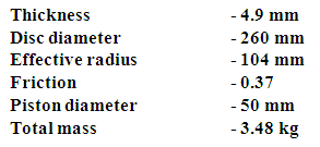
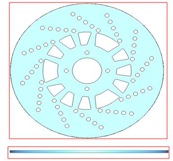 | Figure 1. Disc Brake Model |
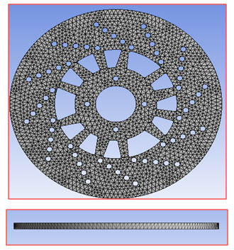 | Figure 2. Brake Meshing Model |
3. Boundary Condition
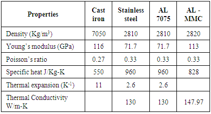
The various materials used for the analysis and its properties are mentioned in the Table 1. The boundary condition used for the simulation are shown in Figures 3 and 4.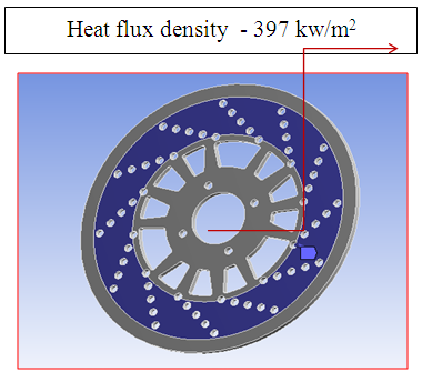 | Figure 3. Disc Heat Flux Density |
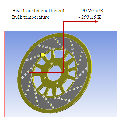 | Figure 4. Disc heat transfer coefficient |
Table 1. Brake Material Property Disc
 |
| |
|
Heat Flux (Q) (W/m²) | (3.1) |
Where,Q = Heat fluxM = Mass of vehicleg = gravitational force V0 = initial velocity of vehicle Model CalculationM = 1000 kgV0 = 100 km/hr = 27.778 m/secG = 9.81m/s²ᵟ = 1ᵒQ = M * g * V0 * sin ᵟ /12 Q = 1000 * 9.81 * 27.778 *0.01745 / 12Q = 396.84Q ≈ 397 kw/m²
4. Analysis
4.1. Research Methodology
There are two major stages involved in this project, which are disc brake design and performance evaluation. In the disc brake design stage, suitable type of disc brake was selected to be installed in hybrid car. Selection criteria were focused on price, system compatibility, and lightweight. Thus, in the end of the selection process, a commercial hybrid car disc brake system was selected for the vehicle. As well as lightweight property and lower cost compared to a passenger car disc brake system. The disc brake system utilized a cross-drilled rotor with fixed caliper design for better heat dissipation. The disc brake rotor is made from carbon ceramics material which provides good wear resistance with high thermal conductivity and the production cost is low compared to other high performance disc brake rotor materials. Also highlighted that although advanced brake materials such as aluminums metal matrix composite offer significant weight advantages compared with the traditional cast iron rotor, the aluminum metal matrix composite material has a much lower maximum operating temperature which limit its application. The hybrid car was installed with all wheel disc brake system to maximize its braking capability and provide higher safety to the driver throughout the race. The vehicle is estimated to weight approximately 2000kg including the driver. During the performance evaluation stage, model of the disc brake selected was developed based on its exact dimensions measured using the Coordinate Measurement Machine (CMM) equipment. The disc brake model was later imported in ANSYS CAE finite element analysis software as the geometry model to perform the performance analysis. Load analysis was also performed to determine the heat flux and convection heat transfer coefficient for the brake system during its operation. Thermal analysis results obtained at the end of the analysis were validated and compared to the allowable material specification for the rotor. If the selected disc brake failed the thermal analysis process, then a new disc brake design will be selected as the replacement. The performance analysis is repeated until the disc brake met the design requirement and the disc brake will be installed on the actual hybrid car later on.
4.2. Finite Element Analysis
A fully coupled thermo mechanical model was set up to predict the temperature changes of the brake disc shape caused by axial and radial deformation. Thermal conduction and convective heat transfer were the two modes of heat transfer considered. The convection heat transfer coefficient was 90 W/m2K over all exposed surfaces, and radiative heat transfer was considered negligible.The vehicle stops from 100 km/h in 4.3 seconds and develops an initial braking power of 107 kW. The simulation wheel rotational speed was set to 93 rad/s equivalent to 100 km/h for single stop braking with the initial disc temperature at 20°C. Heat was generated by pressing each pad on the disc with a uniform pressure of 6 MPa on the piston which created a rapid temperature rise in the disc; in an actual car this would be approximately equivalent to a 60% g deceleration. For the drag braking, loading and boundary conditions were set to represent a constant wheel rotational speed of 28.6 rad/s equal to 30 km/h vehicle speed under drag braking with an initial disc temperature of 20°C. Tyre rolling radius was calculated from the tyre rolling circumference of the test car which was 1860 mm, giving a tyre rolling radius of 0.29 m. The value of heat transfer coefficient used was 90 W/m2K based on the experimental results. The material properties of model are shown.FEA simulation of single stop braking was used to determine the effect of the vehicle mass on front brake temperatures in terms of temperatures and stresses. Equation (4.1) which describes the average heat flux density on each disc was derived based on average braking power over the disc friction area.  | (4.1) |
4.3. Thermal Stress Analysis
Thermal stress was predicted from the temperature distribution during single stop braking. The predicted surface compressive stresses associated with the temperature rise can cause yielding in compression of the material in the disc surface because thermal stresses are much higher than purely mechanical stresses on the friction surface. The thermal stress on a disc surface at the disc effective radius is presented in Figures 9-11 for comparison between different vehicle masses. It can be seen that high initial stresses at the friction surface follow from a high thermal gradient. Thermal stresses for the 2000 kg vehicle mass were close to 384 MPa, which can cause thermal fatigue cracks on the friction surface over time. Brake disc surface cracking only occurs when the thermal stress exceeds the yield stress of the material. Lower thermal stresses are predicted; 317 MPa for 1500 kg and 262 MPa for 1000 kg of vehicle mass. From these results, the discs show lower thermal stress than the maximum tensile stress of the disc material which is 910 MPa.
4.4. Single-Stop Braking
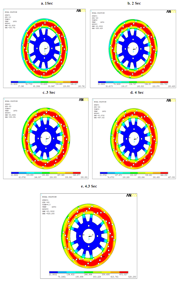
Braking power in a single stop brake was computed assuming no slip at the tire/ground interface and that heat is generated at the friction interface of the brake. The models were analyzed based on a minimum vehicle mass of 1000 kg to compare thermal stress results in medium conditions for single stop. Maximum surface temperatures were predicted at nodes on the disc, e.g. at the effective radius. Figures 9-11 shows the temperature distributions predicted from the models. The lower temperatures predicted (below 200°C) were on models were made of cast iron, stainless steel, Al7075 and AL-MMC. This shows that model ALMMC is the most suitable model in terms of temperature rise, thermal stress and disc coning. The comprehensive stresses associated with these temperature rises can cause yielding in compression of the material in the disc surfaces. Higher values of thermal stress were considered acceptable in lower duty of braking; hence all models were analyzed further. The deformation of the brake disc due to thermal loading is apparent when viewed through the disc cross section. The deformation of the brake disc region is primarily attributed to the thermal expansion of the disc. The magnitude of the coning displacement was calculated from the thermal stress analysis throughout the simulated brake schedule. The result from a sensitivity study of thermal deflection with respect to the disc mass at the end of braking (4 s) is shown in Figures 9-11. Axial displacement (coning) was approximately 0.3 mm. Overall coning prediction was between 0.17 mm to 0.38 mm for all models except the externally vented designs which had a greater axial displacement up to 1.22 mm. Models showed a small amount of axial displacement at the end of braking. Disc coning has to be reduced as well as reducing stresses to minimize disc cracking and instability of a lightweight disc. A further improvement to reduce disc coning is to create slot depth or undercut between friction ring and the hat should be considered. The reason for the undercut is to reduce the stiffness of the joint between the friction disc and the hat. Maximum temperatures obtained from the thermo mechanical analyses show the superiority of cast iron over stainless steel in reducing surface temperature and thermally induced stress. In order to absorb and transmit the heat generated at the friction interface, cast iron has a high volumetric heat capacity (ρCp) and good thermal conductivity compared to stainless steel. Although stainless steel has a low coefficient of thermal expansion to minimize disc coning, it has higher density compared to cast iron.This Model was made of cast iron and had good compressive strength, but at the same time it had low tensile strength as the material was brittle and prone to micro cracking in tension. Model Stainless steel was not practical to use in regenerative braking because of its weight, AL-MMC was more suitable to use in RBS because 30% of the energy is recuperated in the system and this will reduce thermal duty and hence temperature rise, thermal stress and thermal deformation during braking. From the thermo mechanical analyses in single stop braking, a disc made of cast iron (which is the disc carbon ceramic) was selected as a design model for vehicle masses lower than 1500 kg that are equipped with regenerative braking. Disc deflection was investigated for all models as shown in Figure 8. The results show negative values indicating that all models deformed in an axially outward direction. Model had a disc thickness of 8 mm and was made of stainless steel, and this showed the least amount of thermal coning (0.17 mm) of most models but slightly more coning than model. When the temperature reached 50°C. This clearly indicated the effect of the undercut on the friction disc and the “top hat” transition region. Models stainless steel, cast ironAL7075 and AL-MMC (without undercut) revealed the largest amount of coning between temperatures of 50°C to 150°C. Reducing the thermal coning of a brake disc needs an adequate amount of undercut between the transition ring/top hat. Model stainless steel, carbon ceramic and AL7075 has the lowest thermal coning, however this model was not further considered.
4.5. Drag Braking
Figures 5-8 shows that model with 4.9 mm of disc thickness shows a good analysis result in the thermo mechanical analysis. The results also showed a similarity under single stop braking. Therefore model AL-MMC was selected as the prototype lightweight disc because its mass was only 3.48 kg. Model stainless steel was not suitable to use as a lightweight disc because it was heavy compared to model AL-MMC.The total amount of disc coning is shown in Figures 12-13 although model AL-7075 gives the second lowest disc coning compared to Cast iron and Stainless Steel, it shows faster time of axial deformation at 50°C, which has the lowest disc coning. This is because disc is made of stainless steel which has a higher tensile strength but lower thermal conductivity. Table shows the thermal conductivity relationship between cast iron, stainless steel, AL-7075 and AL-MMC.
4.6. Comparison of Temperature in Different Material
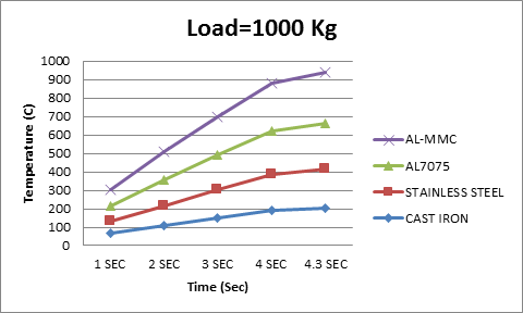 | Figure 5. Temperature in different material for 1000 Kg |
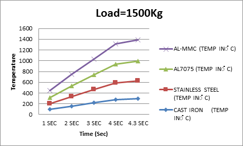 | Figure 6. Temperature in different material for 1500 Kg |
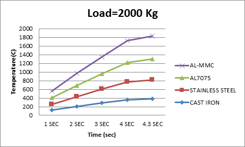 | Figure 7. Temperature in different material for 2000 Kg |
4.7. Comparison of Deformation in Different Material
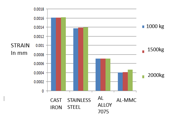 | Figure 8. Deformation of different material |
4.8. Advantages of Aluminium Metal Matrix Composite
In comparison to the conventional grey cast iron brake disk the AL-MMC brake disk weighed round 50 per cent less reducing the unsprung mass.Improved brake response and fading data, high thermal stableness, no hot judder, excellent pedal feel, improved steering behaviour, high abrasion resistance.Longer life time and the advantage of avoiding almost completely brake dust.At first Porsche AG built the AL-MMC brake disk in 2001 into the 911 GT2 as series equipment. Since that time also other premium brands use the advantages of this innovative brake technology for more security and comfort. These are for example sports cars and luxury class limousines from Audi, Bentley, Bugatti and Lamborghini.
5. Conclusions
The design of the connection between the friction ring and 3 the hub is important in a brake disc. The importance of this connection has been recognised and understood for many years and car brake disc designers pay careful attention to the design of the so-called “top hat” region of the disc. Which friction face is mounted to the top hat, and the design of “undercut” both enable coning to be controlled within acceptable limits. However the brake disc of the type proposed here has a completely different temperature profile, both in terms of the magnitude of the temperatures reached during braking, and the distribution of temperature in the disc. This is also known from the use of discs on car but, again the duty levels are much different. This work predicts the magnitude and distribution of temperature in a brake disc for a passenger car and consequently the expected coning. It therefore provides an indication of what design steps must be taken to keep coning to acceptable levels in operation. It can be concluded that AL-MMC is a suitable material for a brake disc in terms of mechanical and thermal strength, provided that the tribological characteristics are suitable (e.g. it might be advantageous to use different pad materials). AL-MMC is suitable to be used for disc thicknesses less than 8 mm because AL-MMC has three times the tensile strength of cast iron. For disc thicknesses of 8 mm or greater cast iron is suitable because of its high thermal conductivity and low Young's modulus, which limit the amount of disc damage caused by the heat flux generated by friction. When choosing the best disc material, aside from the properties which have been referred to in Table I, the heat capacity of the material has been shown to be as significant as the thermal conductivity. Disc material with higher heat capacity can decrease both the maximum surface temperature and the maximum stress applied to the disc surface. But AL-MMC seems to be a good material for a disc, and it is better than AL7075 because of its higher MOT. A disc made of AL-MMC is designed to minimise stresses and distortion. The contribution made by this research work to the field of vehicle braking is twofold. Firstly, the friction brakes can be downsized on a car with braking. Reducing the mass of the brake disc must consider temperatures, stresses, wear, deformation and durability. Second the example developed in this research illustrates that it is possible to reduce the brake disc mass by using a solid disc. The paper also presents a design approach for a brake disc based on mathematical and numerical (CAE) analysis with than associated experimental investigation.Temperature distribution for ALMMC material at Single stop braking time 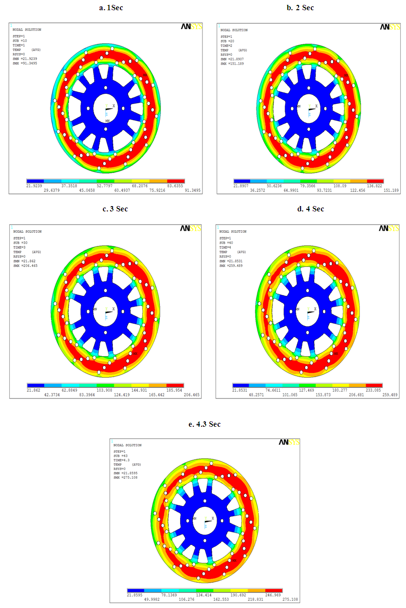 | Figure 9. Single stop braking time for 1000Kg |
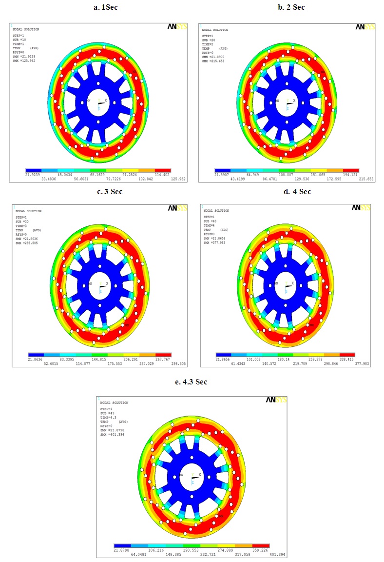 | Figure 10. Single stop braking time for 1500Kg |
 | Figure 11. Single stop braking time for 1500Kg |
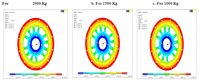 | Figure 12. Maximum Deformation |
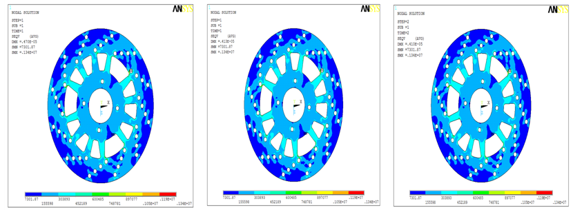 | Figure 13. Maximum Stress |
References
| [1] | G. Oder, M. Reibenschuh, T. Lerher, M. Šraml, B. Šamec, and I. Potrč, Maribor (Slovenia) Thermal and Stress Analysis of Brake Discs in Railway Vehicles Advanced Engineering 3(2009) No. 1, pp. 95-102. |
| [2] | S.B. Sarip, “lightweight friction brakes for a road vehicle with regenerative braking, Ph.D. Thesis. Engineering, Design and technology, Bradford University, 2011. |
| [3] | ABAQUS 6.7.1 – tutorial. 2008. |
| [4] | SIST EN 1563:1998(en). Founding – Spheroidal graphite cast irons. SIST, Ljubljana 1998. |
| [5] | Mackin, T.J.: Thermal cracking in disc brakes. Engineering Failure Analysis (2002), no. 9, str.63-76. |
| [6] | Oder, G.: Determination of non-stationary thermal and stress fields in brake discs. Maribor: Faculty of Mechanical Engineering, 2008. |
| [7] | Reibenschuh, M.: Stress analysis of a brake disc under centrifugal and thermal load. Maribor: Faculty of Mechanical Engineering, 2008. |
| [8] | Z. Zaini et al., “Mixed-mode braking for road vehicles with regenerative braking,” in Proceedings of 6th European Conference on Braking, pp. 101 - 108, 2010. |
| [9] | M. Ehsani et al., Modern electric, hybrid electric, and fuel cell vehicles: fundamentals, theory, and design, Second Editioned. New York: CRC Press, 2009. |
| [10] | A. J. Day and T. P. Newcomb, “The dissipation of frictional energy from the interface of an annular disc brake,” in Proceedings of the Institution of Mechanical Engineers, Part D: Transport Engineering 1984-1988, vol. 198, pp. 201-209, 1984. |
| [11] | T. P. Newcomb, “Stopping revolutions: developments in the braking of cars from the earliest days,” in Proceedings of the Institution of Mechanical Engineers 1847-1982, vol. 195, pp. 139 - 150, 1981. |
| [12] | T. P. Newcomb and N. Millner, “Cooling rates of brake drums and discs,” in Proceedings of the Institution of Mechanical Engineers, Automobile Division 1947-1970, vol. 180, pp. 191-205, 1965. |
| [13] | A. J. Day et al., “A finite element approach to drum brake analysis,” in Proceedings of the Institution of Mechanical Engineers 1847-1982, vol. 193, pp. 401-406, 1979. |
| [14] | T. Hoffman and R. E. V. Druten, “Energy analysis of hybrid vehicle powertrains,” presented at the conference of IEEE Int. Symp. Veh. Power Propulsion, 2004. |
| [15] | A. J. Day, “Drum brake interface pressure distributions,” in Proceedings of the Institution of Mechanical Engineers, Part D: Journal of Automobile Engineering 1989-1996, vol. 205, pp. 127-136, 1991. |
| [16] | R. Chicurel, “A compromise solution for energy recovery in vehicle braking,” Elsevier Science Ltd, vol. 24, pp. 1029-1034, 1999. |
| [17] | S. B. Sarip, “Lightweight friction brakes for a road vehicle with regenerative braking,” Ph.D. Thesis, Engineering, Design and Technology, Bradford University, 2011. |
| [18] | M. M. Muhayen, Vehicle Engineering, University of Bradford, Bradford, 2010. |
| [19] | T. A. Philpot, Mechanic of Materials: An Integrated Leaning System: John Wiley & Sons, Inc, 2007. |
| [20] | J. M. Gere and S. P. Timoshenko, Mechanic of Materials, Stanley Thornes, 1999. |
| [21] | T. Okamura and H. Yumoto, “Fundamental study on thermal behaviour of brake discs,” SAE International, vol. 2006-01-3203, 2006. |
| [22] | M. Ehsani et al., modern electric, hybrid electric, and fuel cell vehicles: fundamentals, theory, and design, Secondeditioned. New York: CRC Press, 2009. |


 Abstract
 Reference
 Full-Text PDF
 Full-text HTML


